0
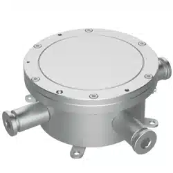
Explosion-Proof Terminal Box
Installation Guide

Terminal Box·Installation Guide
i
Quick Start Guide
© 2022 Hangzhou Hikvision Digital Technology Co., Ltd. All rights
reserved.
About this Manual
The Manual includes instructions for using and managing the
Product. Pictures, charts, images and all other information
hereinafter are for description and explanation only. The
information contained in the Manual is subject to change, without
notice, due to firmware updates or other reasons. Please find the
latest version of this Manual at the Hikvision website
(https://www.hikvision.com/).
Please use this Manual with the guidance and assistance of
professionals trained in supporting the Product.
Trademarks
and other Hikvision’s trademarks and logos are
the properties of Hikvision in various jurisdictions.
Other trademarks and logos mentioned are the properties of their
respective owners.
Disclaimer
TO THE MAXIMUM EXTENT PERMITTED BY APPLICABLE LAW, THIS
MANUAL AND THE PRODUCT DESCRIBED, WITH ITS HARDWARE,
SOFTWARE AND FIRMWARE, ARE PROVIDED “AS IS” AND “WITH ALL
FAULTS AND ERRORS”. HIKVISION MAKES NO WARRANTIES,
EXPRESS OR IMPLIED, INCLUDING WITHOUT LIMITATION,
MERCHANTABILITY, SATISFACTORY QUALITY, OR FITNESS FOR A
PARTICULAR PURPOSE. THE USE OF THE PRODUCT BY YOU IS AT

Terminal Box·Installation Guide
ii
YOUR OWN RISK. IN NO EVENT WILL HIKVISION BE LIABLE TO YOU
FOR ANY SPECIAL, CONSEQUENTIAL, INCIDENTAL, OR INDIRECT
DAMAGES, INCLUDING, AMONG OTHERS, DAMAGES FOR LOSS OF
BUSINESS PROFITS, BUSINESS INTERRUPTION, OR LOSS OF DATA,
CORRUPTION OF SYSTEMS, OR LOSS OF DOCUMENTATION,
WHETHER BASED ON BREACH OF CONTRACT, TORT (INCLUDING
NEGLIGENCE), PRODUCT LIABILITY, OR OTHERWISE, IN CONNECTION
WITH THE USE OF THE PRODUCT, EVEN IF HIKVISION HAS BEEN
ADVISED OF THE POSSIBILITY OF SUCH DAMAGES OR LOSS.
YOU ACKNOWLEDGE THAT THE NATURE OF THE INTERNET
PROVIDES FOR INHERENT SECURITY RISKS, AND HIKVISION SHALL
NOT TAKE ANY RESPONSIBILITIES FOR ABNORMAL OPERATION,
PRIVACY LEAKAGE OR OTHER DAMAGES RESULTING FROM
CYBER-ATTACK, HACKER ATTACK, VIRUS INFECTION, OR OTHER
INTERNET SECURITY RISKS; HOWEVER, HIKVISION WILL PROVIDE
TIMELY TECHNICAL SUPPORT IF REQUIRED.
YOU AGREE TO USE THIS PRODUCT IN COMPLIANCE WITH ALL
APPLICABLE LAWS, AND YOU ARE SOLELY RESPONSIBLE FOR
ENSURING THAT YOUR USE CONFORMS TO THE APPLICABLE LAW.
ESPECIALLY, YOU ARE RESPONSIBLE, FOR USING THIS PRODUCT IN A
MANNER THAT DOES NOT INFRINGE ON THE RIGHTS OF THIRD
PARTIES, INCLUDING WITHOUT LIMITATION, RIGHTS OF PUBLICITY,
INTELLECTUAL PROPERTY RIGHTS, OR DATA PROTECTION AND
OTHER PRIVACY RIGHTS. YOU SHALL NOT USE THIS PRODUCT FOR
ANY PROHIBITED END-USES, INCLUDING THE DEVELOPMENT OR
PRODUCTION OF WEAPONS OF MASS DESTRUCTION, THE
DEVELOPMENT OR PRODUCTION OF CHEMICAL OR BIOLOGICAL
WEAPONS, ANY ACTIVITIES IN THE CONTEXT RELATED TO ANY

Terminal Box·Installation Guide
iii
NUCLEAR EXPLOSIVE OR UNSAFE NUCLEAR FUEL-CYCLE, OR IN
SUPPORT OF HUMAN RIGHTS ABUSES.
IN THE EVENT OF ANY CONFLICTS BETWEEN THIS MANUAL AND THE
APPLICABLE LAW, THE LATTER PREVAILS.
Regulatory Information
Intended Use of the Terminal Box and the Supplied Cable Gland
with Elastomeric Sealing Rings
ATEX: II 2 G D Ex db IIC T6 Gb/Ex tb IIIC T80℃ Db IP68
IECEx: Ex db IIC T6 Gb/Ex tb IIIC T80℃ Db IP68
Hazardous Area Classification: Zone 1, Zone 2, Zone 21, Zone 22.
IP Degree: IP68 (2m, 2h)
Ex Standards:
IEC 60079-0: 2017
IEC 60079-1: 2014
IEC 60079-31: 2013
EN IEC 60079-0: 2018
EN 60079-1: 2014
EN 60079-31: 2014
Specific Conditions of Use
1. The flameproof joints are not intended to be repaired, Contact
the Original manufacture for information on the dimensions of the
flameproof joints.
2. Under explosive dust circumstances, the enclosure of this
equipment may generate an ignition-capable level of electrostatic
charge. Therefore the equipment shall not be installed in a location
where the external conditions are conducive to the build-up of
electrostatic charge on such surfaces. In addition, the equipment
shall only be cleaned with a damp cloth.

Terminal Box·Installation Guide
iv
3. USE FASTENERS WITH YIELD STRESS ≥ 450MPa
Nameplate
Explosion-Proof Terminal Box
WARNING:
DO NOT OPEN WHEN EXPLOSIVE
ATMOSPHERE IS PRESENT
POTENTIAL ELECTROSTATIC
CHARGING HAZARD
– SEE INSTRUCTIONS
Explosion-Proof Terminal Box
WARNING:
DO NOT OPEN WHEN EXPLOSIVE
ATMOSPHERE IS PRESENT
AFTER DE-ENERGIZING, DELAY
5 MINUTES BEFORE OPENING
POTENTIAL ELECTROSTATIC
CHARGING HAZARD
– SEE INSTRUCTIONS
The terminal box can be used in hazardous areas Zone 1, Zone 2,
Zone 21, and Zone 22 where ignitable concentrations of
a) flammable gases, vapors or liquids (with T1 to T6
classification) or
b) combustible dust or ignitable fibers/flyings ARE LIKELY TO
EXIST.
Terminal Box·Installation Guide
v
For model difference, see Section 1.2.
WARNINGS:
1. Ambient Temperature: -40°C to +60°C for the terminal box and the
cable gland with elastomeric sealing rings.
2. When assembly, operation and maintenance, the operator must
follow the requirements of the IEC 60079-14: latest version
Explosive atmosphere- Part 14: Electrical installation design,
selection and erection, beside of the manufacturer’s operation
instruction or its National equivalent.
3. Repair and overhaul shall comply with IEC 60079-19: latest version
or its National equivalent.
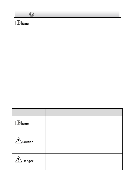
Safety Instruction
The symbols that may be found in this document are defined as
follows.
Symbol
Description
Provides additional information to emphasize
or supplement important points of the main
text.
Indicates a potentially hazardous situation,
which if not avoided, could result in equipment
damage, data loss, performance degradation,
or unexpected results.
Indicates a hazard with a high level of risk,
which if not avoided, will result in death or
serious injury.
Terminal Box·Installation Guide
vi
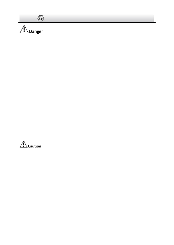
● Grounding:
The both internal and external earthing shall be connected
reliably.
Ground wire cross-sectional area of not less than the phase
connector cross-sectional area level, at least 4 mm
2
.
● All the electrical operation should be strictly compliance with
the electrical safety regulations, fire prevention regulations and
other related regulations of the nation and region.
● To avoid fire danger caused by electrostatic charge, never touch
or wipe the device in explosive environment. Perform the
wiping and replacing accessories only under non-explosive
environment with the anti-electrostatic gloves.
● When the device is installed on wall or ceiling, it shall be firmly
fixed.
● Do not drop the device or subject it to physical shock.
● To ensure explosion-proof performance, do not damage
explosion-proof surface.
● Do not place the device in extremely hot, cold (the operating
temperature shall be -40°C to +60°C), or damp locations, and do
not expose it to high electromagnetic radiation.
● To avoid heat accumulation, good ventilation is required for
operating environment.

Terminal Box·Installation Guide
vii
● To prevent accumulation of electrostatic charge, only damp
cloth can be used during the cleaning.
● While in delivery, the device shall be packed in its original
packing, or packing of the same texture.
● Regular part replacement: a few parts of the equipment shall
be replaced regularly according to their average enduring time.
The average time varies because of differences between
operating environment and using history, so regular checking is
recommended for all the users. Please contact with your dealer
for more details.
● If the product does not work properly, please contact your
dealer or the nearest service center. Never attempt to
disassemble the device yourself. (We shall not assume any
responsibility for problems caused by unauthorized repair or
maintenance.)

Terminal Box·Installation Guide
viii
Table of Contents
1 Introduction ...............................................................................1
1.1 Overview .............................................................................. 1
1.2 Model Description ............................................................... 1
2 Appearance ................................................................................3
3 Installation .................................................................................5
3.1 DS-2781 and DS-2783 Series Installation ........................... 5
3.2 DS-2780 and DS-2782 Series Installation ......................... 11

Terminal Box·Installation Guide
1
1 Introduction
1.1 Overview
Explosion-proof terminal box is specially designed for camera wiring
in explosive environment.
Explosion-proof terminal box adopts stainless steel enclosures,
receiving an IP68 rating for ingress protection.
Application Scenarios: oil industry, chemical industry, port, grain
processing industry, etc.
1.2 Model Description
This manual is applicable to the following models:
Table 1-1 Applicable Model and Feature
Product Model
Power Adapter
Preinstalled
Cable Gland Use
DS-2781ZJ-X
DS-2781ZJ-X/316L
DS-2783ZJ-X
Yes
Input: 110 to 240 VAC
Output: 12 VDC
Use cable gland sealed
with setting compound
(buy separately)
DS-2780ZJ-X
DS-2780ZJ-X/316L
DS-2782ZJ-X
No
Input/Output: 110 to 240
VAC
Use cable gland with
elastomeric sealing rings
(included in package)
Terminal Box·Installation Guide
2
Buy certified cable glands in advance for DS-2781 and
DS-2783 series terminal box. For recommended models, see
below.
For DS-2780 and DS-2782 series terminal box, flexible conduit
is supported with supplied M25 to G3/4 adapters.
Table 1-2 Recommended Cable Gland Sealed with Setting Compound
Brand
Model
Hawke
ICG623/B-M25 SS
CMP
N.P Brass 25 PX2KX REX M25
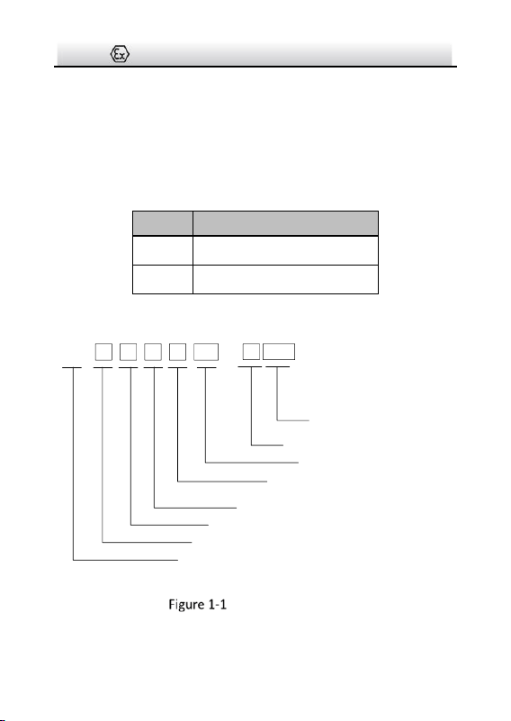
Explanation of model naming:
DS- 2 7 8 0 ZJ
-
X /316L
Hikvision product
Front-end product
Material: stainless steel
Product type: terminal box
Product series
Power adapter included: 1 and 3
NO power adapter: 0 and 2
Product type: accessory
Stainless Steel Type:
With /316L: stainless steel 316L
Without /316L: stainless steel 304
Feature: explosion-proof
Model Explanation
Terminal Box·Installation Guide
3
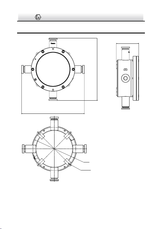
2 Appearance
272
272
96.8
Ø 182
4-Ø 8.5
EQS
Unit: mm
Figure 2-1 Explosion-Proof Terminal Box Overview
Terminal Box·Installation Guide
4
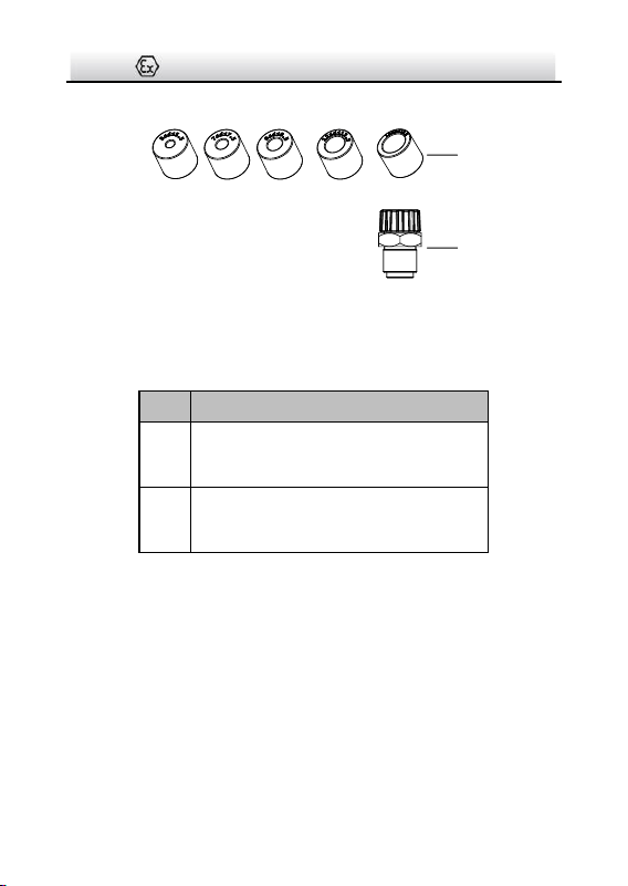
1
2
Figure 2-2 Elastomeric Sealing Rings Overview
Table 2-1 Accessory Description
No.
Description
1
Elastomeric sealing rings
(DS-2780 and DS-2782 series included)
2
M25×1.5 to G3/4 adapter
(DS-2780 and DS-2782 series included)

Terminal Box·Installation Guide
5
3 Installation
Before you start:
● Make sure the device in the package is in good condition and all
the assembly parts are included.
● Make sure all the related equipment is power-off during the
installation.
● Check the specification of the products for the installation
environment.
● Standard power input for DS-2781 and DS-2783 series is 110 to
240 VAC.
● DS-2780 and DS-2782 series supports multiple power types.
Make sure the power meets anyone of 110 to 240 VAC, 24 VAC,
8 to 36 VDC, PoE (802.3af), and PoE (802.3at).
● Make sure that the wall is strong enough to withstand four
times the weight of the device.
● Keep the device from bumps or scratches during installation.
3.1 DS-2781 and DS-2783 Series Installation
Before you start:
Cable gland sealed with setting compound is required for the
terminal box installation.
Buy two certified cable glands in advance for desired using
environment. For recommended models, see Section 1.2.
Terminal Box·Installation Guide
6
Steps:
1. Drill four screw holes (Ø8 mm) according to the dimension of the
terminal box (see Figure 2-1), and insert four M8 × 80 expansion
bolts.
2. Secure the terminal box on mounting place.
Nut
Spring Washer
Flat Washer
Figure 3-1 Secure Terminal box
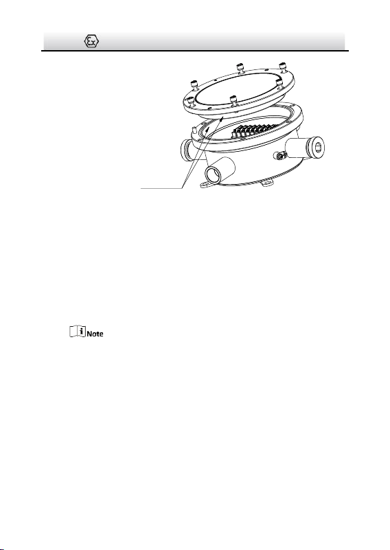
3. Disassemble the terminal box.
Terminal Box·Installation Guide
7
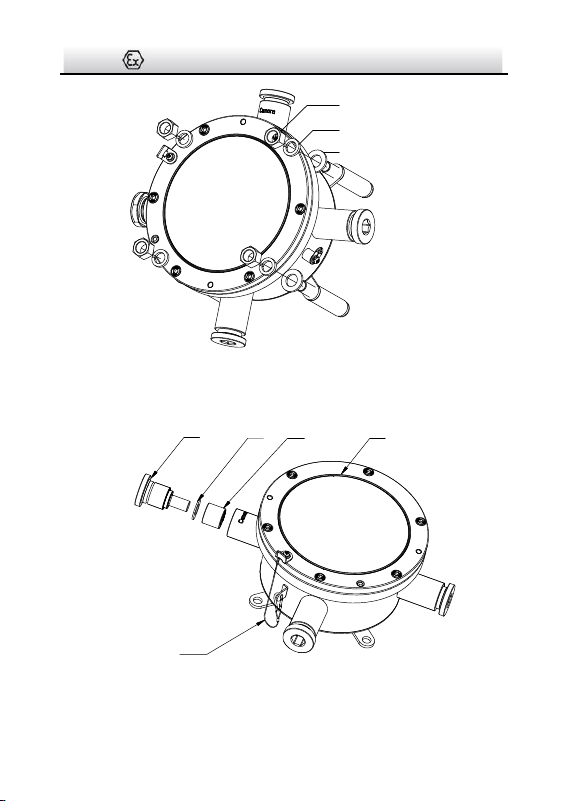
CoverSealing RingGasket
Plug
Safety Rope
Figure 3-2 Disassemble Terminal Box (1)
1). Loosen the plugs at “Camera” end and its opposite end, and
take out the gaskets and the sealing rings.
Normally, two ends are enough for cable routing. The others
are reserved for unexpected conditions.
Keep the unused ends firmed sealed (torque 50 Nm).
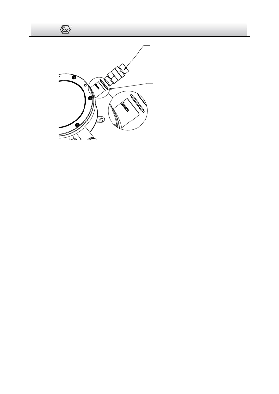
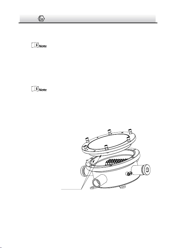
2). Unscrew and remove the cover.
When removing the cover,
● Do NOT release the safety rope.
● Prevent the explosion suppression surfaces from bump or
scratch.
Terminal Box·Installation Guide
8
Explosion Suppression
Surface
Figure 3-3 Disassemble Terminal Box (2)
4. Route cables and wiring.
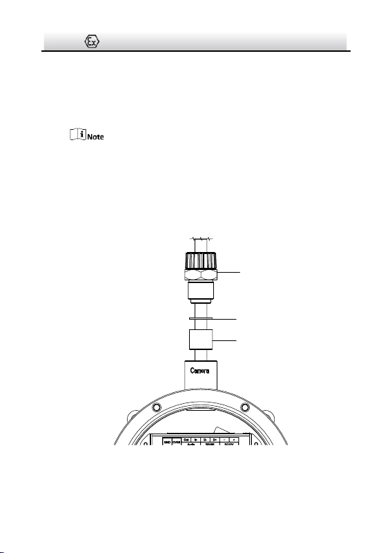
1). Install the camera cable to cable gland (sealed with setting
compound). Refer to installation guide of the cable gland for
detailed steps.
2). Secure the cable gland together with the cable gland sealing
ring (a component of cable gland) to the “Camera” end.
For the torque information, refer to the installation guide of
the cable gland.
Terminal Box·Installation Guide
9
Cable Gland
Cable Gland Sealing Ring
Figure 3-4 Install Camera Cable
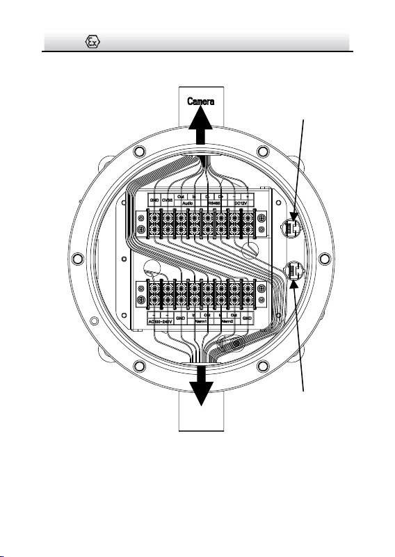
3). Connect wires to corresponding terminals.
4). Install a RJ45 head to network cables and plug it to RJ45①.
5). Repeat above steps to route source cables through the
opposite “Camera” end, connect wires, install a RJ45 head and
plug it to RJ45②.
Terminal Box·Installation Guide
10
To Camera
To Source
RJ45①
RJ45②
Figure 3-5 Wiring
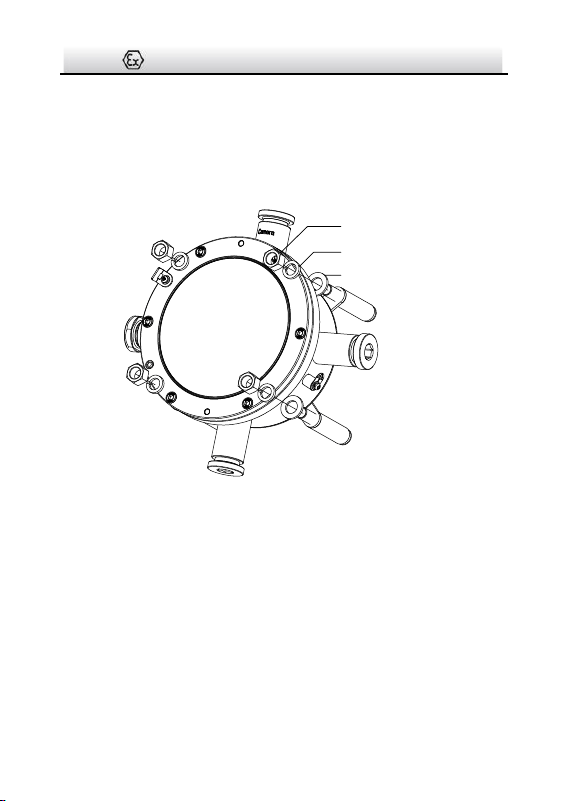
5. Screw the cover back to terminal box.
Terminal Box·Installation Guide
11
1). Check to ensure the O-shape ring stays in terminal box.
2). Align the locating hole of the cover with the locating pin on
box, and gently lower the cover back to the box.
When lowering the cover, prevent the explosion suppression
surfaces from bump or scratch.
3). Tighten the screws (torque 1.2 Nm).
Locating Hole
Locating Pin
O-Shape Ring
Explosion Suppression
Surface
Torque 1.2 Nm
Figure 3-6 Install Cover Back
3.2 DS-2780 and DS-2782 Series Installation
Steps:
1. Drill four screw holes (Ø8 mm) according to the dimension of the
terminal box (see Figure 2-1), and insert four M8 × 80 expansion
bolts.
2. Secure the terminal box on mounting place.
Terminal Box·Installation Guide
12
Nut
Spring Washer
Flat Washer
Figure 3-7 Secure Terminal box
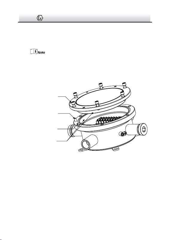
3. Disassemble the terminal box.
CoverSealing RingGasket
Plug
Safety Rope
Figure 3-8 Disassemble Terminal Box (1)
Terminal Box·Installation Guide
13
1). Loosen the gland nuts at the “Camera” end and the opposite
“Camera” end, and take out the gaskets and the sealing rings.
Normally, two ends are enough for cable routing. The others
are reserved for unexpected conditions.
Keep the unused ends firmed sealed (torque 50 Nm).
2). Unscrew and remove the cover.
When removing the cover,
● Do NOT release the safety rope.
● Prevent the explosion suppression surfaces from bump or
scratch.
Explosion Suppression
Surface
Figure 3-9 Disassemble Terminal Box (2)
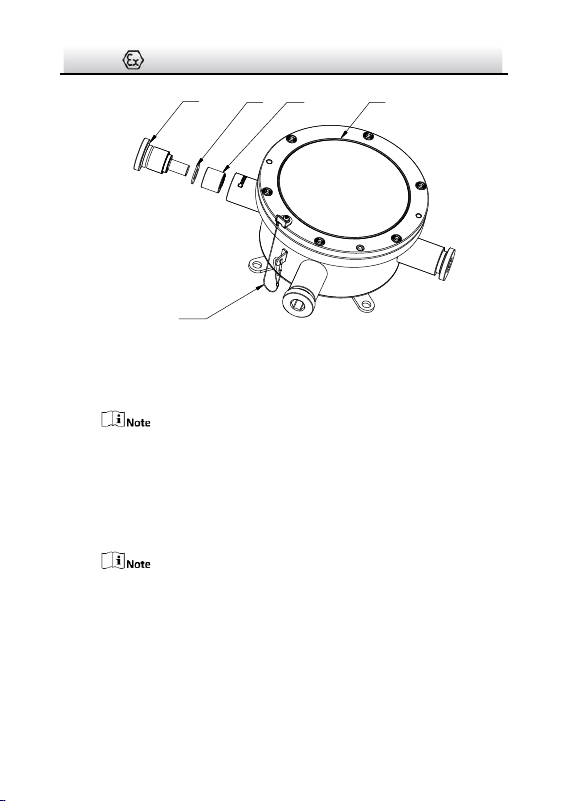
4. Route cables. Cable routing with and without flexible conduit are
different.
Terminal Box·Installation Guide
14
If camera is NOT protected by flexible conduit, follow these
steps:
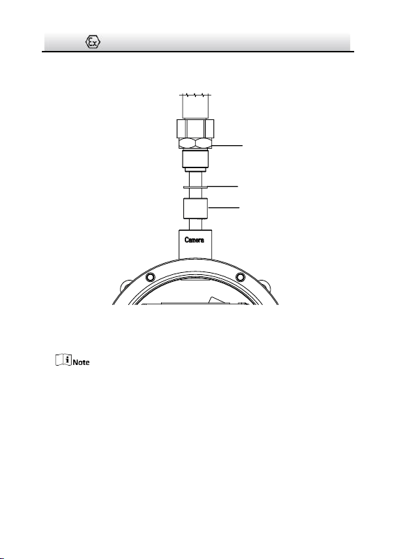
1). Thread the camera cable through supplied adapter, gasket,
and supplied sealing ring.
Select a suitable sealing ring according to the diameter of your
cable. Several kinds of sealing rings are supplied (Ø15 mm,
Ø12 mm, Ø9 mm, Ø7 mm, and Ø5 mm).
2). Secure the gland nut to the “Camera” end with wrench
(torque 50 Nm).
M25 to G¾
Adapter
Gasket
Sealing Ring
(torque 50 Nm)
Figure 3-10 Install Camera Cable
If camera is protected by flexible conduit, follow these steps:
Terminal Box·Installation Guide
15
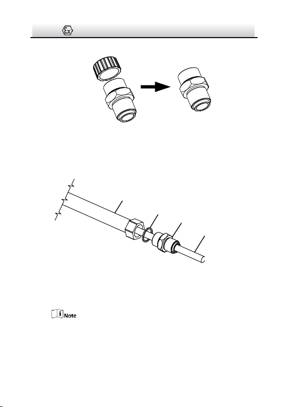
1). Remove the thread cap on supplied adapter.
Figure 3-11 Remove Cap on Supplied Adapter
2). Thread the camera cable through sealing ring (together with
flexible conduit) and the adapter, and secure the adapter to
the conduit.
Conduit
Sealing Ring of Conduit
Adapter
Camera Cable
Figure 3-12 Install Adapter to Conduit
3). Thread the camera cable through the adapter, gasket, supplied
sealing ring, and the box outlet.
Select a suitable sealing ring according to the diameter of your
cable. Several kinds of sealing rings are supplied (Ø15 mm,
Ø12 mm, Ø9 mm, Ø7 mm, and Ø5 mm).
Terminal Box·Installation Guide
16
4). Secure the adapter to the “Camera” end with wrench (torque
50 Nm).
Gasket
Adapter
Torque 50 Nm
Sealing Ring
Figure 3-13 Secure the Adapter to Terminal Box
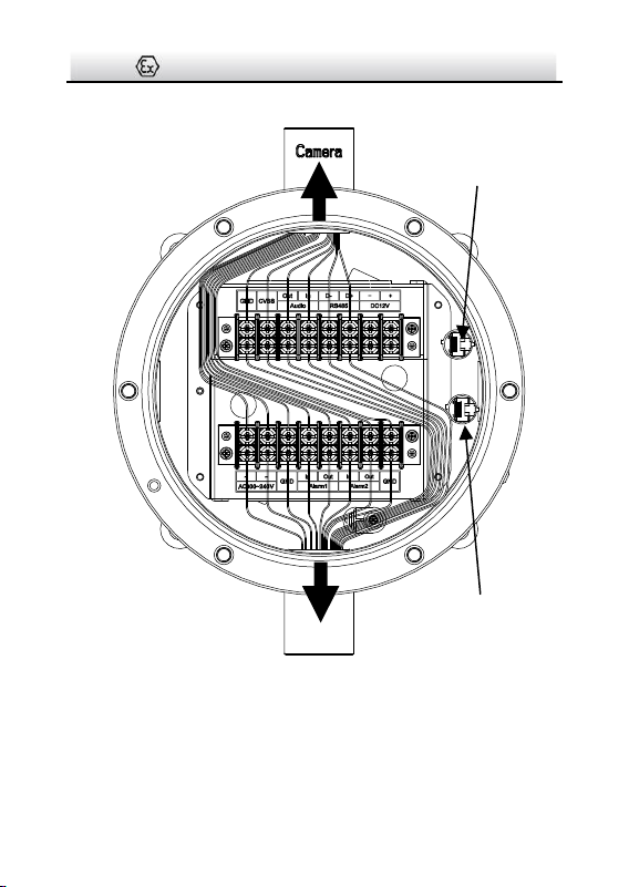
5. Connect wires to corresponding terminals.
This terminal box transmits power without making any change to
it.
Terminal Box·Installation Guide
17
To Camera
RJ45①
To Source
RJ45②
Figure 3-14 Wiring
1). Install a RJ45 head to network cables and plug it to RJ45①.
Terminal Box·Installation Guide
18
2). Repeat above steps to route source cables through the
opposite “Camera” end, connect wires, install a RJ45 head and
plug it to RJ45②.
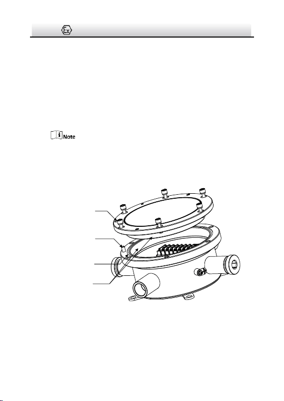
6. Screw the cover back to terminal box.
1). Check to ensure the O-shape ring stays in terminal box.
2). Align the locating hole of the cover with the locating pin on
box, and gently lower the cover back to the box.
When lowering the cover, prevent the explosion suppression
surfaces from bump or scratch.
3). Tighten the screws (torque 1.2 Nm).
Locating Hole
Locating Pin
O-Shape Ring
Explosion Suppression
Surface
Torque 1.2 Nm
Figure 3-15 Install Cover Back

19
UD08260B-B