


IR
Transmitter Features
Handheld Transmitter Option
1. Microphone head with cartridge inside
2. Metal pipe (Aluminum alloy)
Anodize any different colors, never fade.
3. Backlit LCD
Display group, channel, frequency and battery life.
4. IR infrared port
Receiver infrared beam to synchronize frequencies, hold the transmitter with its IR
port facing directly towards the receiver’s IR port with a distance between 5-20cm.
Note: When using multiple systems, only one transmitter IR port should be sync’d
at a time.
5. ON/OFF and Mute switch
Push up the switch to turn on, Mute at the mid position
6. Battery compartment
To replace batteries, unscrew the bottom pipe part counter-clockwise, make
sure to put the battery in the right polar directions
7. Caps-on ( three different choices)
1
2
5
3
777
4
6
4


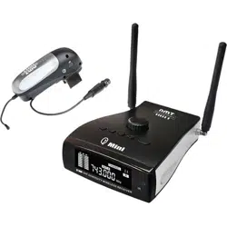
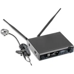
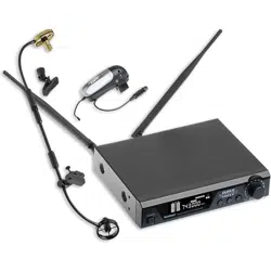
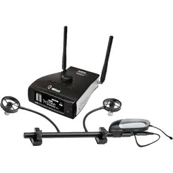
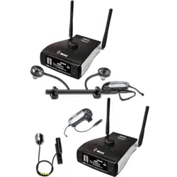
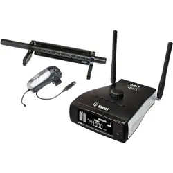
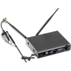
Acoustic Instrument Transmitter
6
1.Each AMT microphone has a disconnect. (D.C.T.) Connect the cable from the Q7
Transmitter to the 3pin (Ta3) input connector on the microphone.
2.Adjustable Gooseneck
Adjustable at angle to allow sound to escape from instrument and develop naturally.
3.Mounting Screw
To REINFORCE the transmitter’s stability on the bell of saxophone / horn, rubber
protection avoids damage of the instrument.
4.BATT/PO
Power and battery LED, the blue LED remains lit as long as the transmitter has power;
if the blue LED is flashing, the battery need to be replaced immediately.
5.Mute Button
6.Light touch power switch
Tap to turn on, long press (2 seconds) to turn off.
7.Antenna
1/4 wave-length wire type antenna, MUST be fully connected and extended during
normal operations. Reception will be poor without antennas connected.
8.IR infrared port
Receiver infrared beam to synchronize frequencies, hold the transmitter with its IR
port facing directly towards the receiver’s IR port with a distance between 5-20cm.
9.Battery compartment
Insert a standard AA alkaline battery here, make sure to put the battery in the right
polar directions.
10.Battery cover
Pull back gently on this cover at the ribbing and pry upwards to remove

7
System Setup
1.Connect the included AC power supply to the rear of the receiver and turn on the receiver.
2.Standard Display
The standard display shows the preselected group and channel.
Group
Channel
Push the SET button and hold for 1 second, the GROUP icon will blink. Push the up
and down buttons to set the desired group (01-10), Press SET again to confirm.
The display will return to the standard operating setting after a short period of non-
activity automatically.
NOTE: Each group 01-10 consists of 10 channels, each corresponding to a specific
frequency. Some frequency bands, for specific regions, will not have 10 channels
per group. (Groups vary by region.)
After setting the group, press SET again, the CHANNEL will blink. Push the up and
down buttons to set the desired channel (01-10 region dependent) Press SET again
to confirm.
The display will return to the standard operating appearance after a short period of
non-activity automatically.

8
System Setup
IR Sync
After setting channel, press the SET again, the IR Icon will blink (picture 1). Push the
SET button and hold for 1 second, the receiver will start to send the infrared signals
(picture 2), then put the transmitter (handheld, body-pack or musical instrument) IR
port close to the receiver’s IR port. The transmitter has to be synchronized to the same
frequency (group and channel) before using. After a successful sync, the display RF
signal and Antenna icon appears. (Picture 3)
1
2
3

9
System Setup
Transmitter / Receiver IR Quick Sync
With the receiver in normal operating mode, and the TRANSMITTER OFF, push and
hold the SET button on the receiver to sync the transmitter to the receiver. While the
receiver is sending the signal, turn the transmitter ON. If, for some reason, your
transmitter is not on the same channel from the last usage, you can use the IR Quick
Sync method to quickly sync the transmitter without having to page through the
group and channel setting functions.
Transmitter Sync’ing
When sync’ing the transmitter, it is best to power the transmitter OFF first, then
power the transmitter on while your sending the sync from the receiver. This
procedure will re-set the transmitter, allowing for it to sync to the newly selected
channel before it locks / syncs to a channel on the receiver.

10
Specifications
Receiver
Frequency Preparation PLL Synthesized Control
Frequency Range 600-952MHz(Region dependent)
Frequency Type F3E
Modulation Type FM
Channels 100(10x10)
Oscillation System VCO
Type of reception True Diversity
Receive Sensitivity -11dBm (sinad≥30dB)
Frequency Response 60Hz-17KHz+/-3dB
S/N Ratio ≥105dB
T.H.D <0.5% at 1KHz
Dynamic Range >100dB
Operating Temperature -10-+50℃
Display Backlit LCD (63mm*22mm)
Audio Output 1*Balanced XLR Socket 1*6.35mm Jack
Antenna 2*BNC
Power Supply DC12V-18V/500mA
Dimensions( L*W*H) 210*170*44mm
Handheld Transmitter
Frequency Preparation PLL Synthesized Control
Frequency Range 600-952MHz(Region dependent)
Frequency Deviation ±48KHz
Microphone Type Dynamic
Polar Pattern Cardioid
RF Output Power 10mW
Controls ON/MUTE/OFF
Indicators Backlit LCD
Interface Infrared
Power Supply 2*AA battery
Operating Voltage 3V
Operating time 10h (depending on batteries)
Dimensions 265mm

11
Specifications
Body-pack Transmitter
Frequency Preparation PLL Synthesized Control
Frequency Range 600-952MHz(Region dependant)
Frequency Deviation ±48KHz
Input 3 pin mini-XLR
RF Output Power 10mW
Controls Power ON//OFF, Volume, SET frequency
Indicators LED (PO), LCD(BATT, frequency)
Interface Infrared
Antenna 1/4 wave Length Wire Type
Power Supply 2*AA battery
Operating Voltage 3V
Operating time 10h (depending on batteries)
Dimensions( L*W*H) 110*63*21mm
Acoustic Instrument Transmitter
Frequency Preparation PLL Synthesized Control
Frequency Range 600-952MHz(Region dependent)
Microphone Type Condenser
Frequency Deviation ±48KHz
RF Output Power 10mW
Controls ON/OFF, MUTE
Indicators LED(PO/BATT)
Interface Infrared
Antenna 1/4 wave Length Wire Type
Power Supply 1*AA battery
Operating Voltage 1.2-1.5V
Operating time 10h (depending on batteries)
Dimensions 115*25*62mm

606-614(100CH,10*10)
2组信道3组信道4组信道5组信道
6组信道7组信道8组信道9组信道10组信道
第1组信道第第第第
第第第第第
CH1=606.00MHZCH1=606.80MHZCH1=607.60MHZCH1=608.40MHZCH1=609.20MHZ
CH2=606.08MHZCH2=606.88MHZCH2=607.68MHZCH2=608.48MHZCH2=609.28MHZ
CH3=606.16MHZCH3=606.96MHZCH3=607.76MHZCH3=608.56MHZCH3=609.36MHZ
CH4=606.24MHZCH4=607.04MHZCH4=607.84MHZCH4=08.64MHZCH4=609.44MHZ
CH5=606.32MHZCH5=607.12MHZCH5=607.92MHZCH5=608.72MHZCH5=609.52MHZ
CH6=606.40MHZCH6=607.20MHZCH6=608.00MHZCH6=608.80MHZCH6=609.60MHZ
CH7=606.48MHZCH7=607.28MHZCH7=608.08MHZCH7=608.88MHZCH7=609.68MHZ
CH8=606.56MHZCH8=607.36MHZCH8=608.16MHZCH8=608.96MHZCH8=609.76MHZ
CH9=606.64MHZCH9=607.44MHZCH9=608.24MHZCH9=609.04MHZCH9=609.84MHZ
CH10=606.72MHZCH10=607.52MHZCH10=608.32MHZCH10=609.12MHZCH10=609.92MHZ
CH1=610.00MHZCH1=610.80MHZCH1=611.60MHZCH1=612.40MHZCH1=613.20MHZ
CH2=610.08MHZCH2=610.88MHZCH2=611.68MHZCH2=612.48MHZCH2=613.28MHZ
CH3=610.16MHZCH3=610.96MHZCH3=611.76MHZCH3=612.56MHZCH3=613.36MHZ
CH4=610.24MHZCH4=611.04MHZCH4=611.84MHZCH4=612.64MHZCH4=613.44MHZ
CH5=610.32MHZCH5=611.12MHZCH5=611.92MHZCH5=612.72MHZCH5=613.52MHZ
CH6=610.40MHZCH6=611.20MHZCH6=612.00MHZCH6=612.80MHZCH6=613.60MHZ
CH7=610.48MHZCH7=611.28MHZCH7=612.08MHZCH7=612.88MHZCH7=613.68MHZ
CH8=610.56MHZCH8=611.36MHZCH8=612.16MHZCH8=612.96MHZCH8=613.76MHZ
CH9=610.64MHZCH9=611.44MHZCH9=612.24MHZCH9=613.04MHZCH9=613.84MHZ
CH10=610.72MHZCH10=611.52MHZCH10=612.32MHZCH10=613.12MHZCH10=613.92MHZ
Frquency List
823 - 832MHz (90CH)
Group 1Group 2Group 3Group 4Group 5Group 6Group 7
3 MHz Guard
Band, nominal
3 MHz Guard
Band, nominal
1 MHz Guard
Band, nominal
1 MHz Guard
Band, nominal
1 MHz Guard
Band, nominal
3 MHz Guard
Band, nominal
500MHz Guard
Band, nominal
CHANNEL
1
2
3
4
5
6
7
ABCDEFH
827.45
826.3
828.85
827.325
826.2
828.95
827.175
828.575
826.175
827.825
826.875
829.175
825.3
824.225
830.925
827.975
826.575
825.625
829.725
824.1
830.95
827.025
828.575
825.925
829.55
830.95
824.2
827.9
826.575
828.85
824.825
830.3
823.625
831.375
Group 9Group 10Group 11Group 12Group 13Group 14Group 15
125MHz Guard
Band, nominal
125MHz Guard
Band, nominal
125MHz Guard
Band, nominal
125MHz Guard
Band, nominal
125MHz Guard
Band, nominal
125MHz Guard
Band, nominal
LNOPR
U
Y
826.8
827.1
827.45827.075827.95827.1827.825827.375
828.225828.575826.25825.825826.575828.45826.475828.475
825.825826.1829.525829.25828.9826.15828.775825.9
830.1830.525824.725830.65824.75824.575830.25824.95
824.225824.475830.475824.275830.4830.475824.7830.15
831.4823.35823.65831.65823.55823.475831.325831.375
823.125831.825831.825823.15831.475831.7823.5823.6
Group 8
I
500MHz Guard
Band, nominal
500MHz Guard
Band, nominal
12
Group 1Group 2Group 3Group 4Group 5
Group 6Group 7Group 8Group 9Group 10

13
Frquency List
863-865MHz(16CH, 4*4)
1组信道2组信道3组信道4组信道第第第第
CH1=863.000MHZCH1=863.500MHZCH1=864.000MHZCH1=864.500MHZ
CH2=863.125MHZCH2=863.625MHZCH2=864.125MHZCH2=864.625MHZ
CH3=863.250MHZCH3=863.750MHZCH3=864.250MHZCH3=864.750MHZ
CH4=863.375MHZCH4=863.875MHZCH4=864.375MHZCH4=864.875MHZ
902-928MHz(100CH, 10*10)
1组信道2组信道3组信道4组信道5组信道
6组信道7组信道8组信道9组信道10组信道
第第第第第
第第第第第
CH1=905.00MHZCH1=906.00MHZCH1=907.00MHZCH1=908.00MHZCH1=909.00MHZ
CH2=905.10MHZCH2=906.10MHZCH2=907.10MHZCH2=908.10MHZCH2=909.10MHZ
CH3=905.20MHZCH3=906.20MHZCH3=907.20MHZCH3=908.20MHZCH3=909.20MHZ
CH4=905.30MHZCH4=906.30MHZCH4=907.30MHZCH4=908.30MHZCH4=909.30MHZ
CH5=905.40MHZCH5=906.40MHZCH5=907.40MHZCH5=908.40MHZCH5=909.40MHZ
CH6=905.50MHZCH6=906.50MHZCH6=907.50MHZCH6=908.50MHZCH6=909.50MHZ
CH7=905.60MHZCH7=906.60MHZCH7=907.60MHZCH7=908.60MHZCH7=909.60MHZ
CH8=905.70MHZCH8=906.70MHZCH8=907.70MHZCH8=908.70MHZCH8=909.70MHZ
CH9=905.80MHZCH9=906.80MHZCH9=907.80MHZCH9=908.80MHZCH9=909.80MHZ
CH10=905.90MHZCH10=906.90MHZCH10=907.90MHZCH10=908.90MHZCH10=909.90MHZ
CH1=910.00MHZCH1=911.00MHZCH1=912.00MHZCH1=913.00MHZCH1=914.00MHZ
CH2=910.10MHZCH2=911.10MHZCH2=912.10MHZCH2=913.10MHZCH2=914.10MHZ
CH3=910.20MHZCH3=911.20MHZCH3=912.20MHZCH3=913.20MHZCH3=914.20MHZ
CH4=910.30MHZCH4=911.30MHZCH4=912.30MHZCH4=913.30MHZCH4=914.30MHZ
CH5=910.40MHZCH5=911.40MHZCH5=912.40MHZCH5=913.40MHZCH5=914.40MHZ
CH6=910.50MHZCH6=911.50MHZCH6=912.50MHZCH6=913.50MHZCH6=914.50MHZ
CH7=910.60MHZCH7=911.60MHZCH7=912.60MHZCH7=913.60MHZCH7=914.60MHZ
CH8=910.70MHZCH8=911.70MHZCH8=912.70MHZCH8=913.70MHZCH8=914.70MHZ
CH9=910.80MHZCH9=911.80MHZCH9=912.80MHZCH9=913.80MHZCH9=914.80MHZ
CH10=910.90MHZCH10=911.90MHZCH10=912.90MHZCH10=913.90MHZCH10=914.90MHZ
Group 6Group 7Group 8Group 9Group 10
Group 1Group 2Group 3Group 4Group 5
Group 1Group 2Group 3Group 4

The specification won’t do any further notice for the improvement
Actual product will not be as pictured