
These instructions accompanying the product are the original instructions. This document is part of the product, keep
it for the life of the product passing it on to any subsequent holder of the product. Read all these instructions before
assembling, operating or maintaining this product.
This manual has been compiled by Draper Tools describing the purpose for which the product has been designed,
and contains all the necessary information to ensure its correct and safe use. By following all the general safety
instructions contained in this manual, it will ensure both product and operator safety, together with longer life of the
product itself.
AlI photographs and drawings in this manual are supplied by Draper Tools to help illustrate the operation of
the product.
Whilst every effort has been made to ensure the accuracy of information contained in this manual, the Draper Tools
policy of continuous improvement determines the right to make modifications without prior warning.
20V
COMBI DRILL KIT
03509
MULTI-TOOL BATTERY SYSTEM

1. TITLE PAGE
1.1 INTRODUCTION:
USER MANUAL FOR: 20V Combi Drill Kit
Stock No: 03509
Part No: D20ECD28SET

2. CONTENTS
1. TITLE PAGE
1.1 INTRODUCTION ......................................................................................................... 2
1.2 REVISION HISTORY .................................................................................................. 2
1.3 UNDERSTANDING THIS MANUAL ............................................................................ 2
1.4 COPYRIGHT © NOTICE.............................................................................................. 2
2. CONTENTS
2.1 CONTENTS..................................................................................................................3
3. WARRANTY
3.1 WARRANTY ................................................................................................................4
4. INTRODUCTION
4.1 SCOPE......................................................................................................................... 5
4.2 SPECIFICATION .......................................................................................................... 5
4.3 HANDLING & STORAGE............................................................................................. 6
5. HEALTH AND SAFETY INFORMATION
5.1 GENERAL SAFETY INSTRUCTIONS FOR POWER TOOL USE ............................7-8
5.2 ADDITIONAL SAFETY INSTRUCTIONS FOR COMBI DRILL..................................... 8
5.3 RESIDUAL RISK .......................................................................................................... 9
5.4 SAFETY INSTRUCTIONS FOR MAINS POWERED CHARGERS &
BATTERY PACKS ...................................................................................................9-10
5.5 CONNECTION TO THE POWER SUPPLY (CHARGER) .......................................... 10
6. TECHNICAL DESCRIPTION
6.1 IDENTIFICATION ....................................................................................................... 11
7. UNPACKING AND CHECKING
7.1 PACKAGING .............................................................................................................. 12
7.2 D20 MULTI-TOOL INTERCHANGEABLE BATTERY SYSTEM ................................. 12
7.3 WHAT’S IN THE BOX................................................................................................. 12
8. PREPARING THE DRILL
8.1 BATTERY PACK CHARGING ...............................................................................13-14
8.2 BATTERY PACK PROTECTION FEATURES ............................................................14
8.3 BATTERY PACK CHARGE STATUS.......................................................................... 14
8.4 BATTERY LIFE EFFICIENCY AND CHARGING ADVICE ......................................... 14
9. BASIC COMBI DRILL OPERATIONS
9.1 INSTALLING AND REMOVING BITS......................................................................... 15
9.2 ROTATIONAL DRIVE SELECTION............................................................................ 15
9.3 VARIABLE SPEED TRIGGER.................................................................................... 16
9.4 TORQUE SELECTION CONTROL ............................................................................ 16
9.5 TWO SPEED GEAR BOX .......................................................................................... 16
9.6 BELT CLIP ................................................................................................................. 17
9.7 LED WORKLIGHT ..................................................................................................... 17
9.8 SCREWDRIVING ....................................................................................................... 18
9.9 DRILLING WOOD AND PLASTIC.............................................................................. 18
9.10 DRILLING METAL ...................................................................................................... 18
9.11 DRILLING MASONRY ............................................................................................... 18
10. OPTIONAL ACCESSORIES
10.1 OPTIONAL ACCESSORIES....................................................................................... 19
11 MAINTENANCE & TROUBLESHOOTING
11.1 MAINTENANCE ......................................................................................................... 20
11.2 TROUBLESHOOTING GUIDE...................................................................................20
12. DISPOSAL
12.1 DISPOSAL..................................................................................................................21
12.2 BATTERY PACK DISPOSAL INFORMATION............................................................21
13. EXPLANATION OF SYMBOLS
13.1 EXPLANATION OF SYMBOLS ..................................................................................22
DECLARATION OF CONFORMITY .............................................................................. ENCLOSED
- 3 -

3. WARRANTY
- 4 -
3.1 WARRANTY
Draper power tools have been carefully tested & inspected and are guaranteed to be free from
defective materials or workmanship.
For details of warranty and terms and conditions please visit the Draper Tools website at
www.drapertools.com/warranty

4. INTRODUCTION
4.1 SCOPE
This cordless drill is designed for use with a variety of drill bits, intended for drilling holes in wood,
plastic, metal, brick etc.
This product is intended for domestic and infrequent light trade use only. Any application other
than that it was intended for, is considered misuse.
4.2 SPECIFICATION
Stock no. ................................................................................................................................. 03509
Part no. ..................................................................................................................... D20ECD28SET
Drilling capacity:
Wood .................................................................................................................................... 26mm
Mild steel .............................................................................................................................. 10mm
Masonry ................................................................................................................................. 6mm
Maximum torque........................................................................................................................28Nm
Torque settings ................................................................................................................... 20+1+1+1
Speed (No load) ............................................................................................................... 0-350r/min
Impact rate ................................................................................................................... 0-19,200bpm
Chuck type .................................................................................................................10mm Keyless
Sound pressure level
(LpA)*:
......................................................................... 77.13dB(A), K=3dB(A)
Sound power level
(LWA)**:
........................................................................... 80.48dB(A), K=3dB(A)
Uncertainty (K): .......................................................................................................................... 3dB(A)
Vibration level hammer drilling in metal
†
:.............................................................
1.142m/s²
, K=1.5
m/s
2
Vibration level hammer drilling in concrete
†
:..........................................................
5.76m/s²
, K=1.5
m/s
2
Weight (machine only)............................................................................................................. 0.95kg
†
When sawing in wood.
Battery pack 55887:
Part No. ..........................................................................................................................D20B2.0AH
Type ........................................................................................................................................Li-ion
Rated Voltage ........................................................................................................................... 20V
Rating ..................................................................................................................................... 2.0Ah
Charger 97914:
Part No. ............................................................................................................................D20BCS/2
Rated Voltage ....................................................................................................................... 230V~
Rated Frequency ..................................................................................................................... 50Hz
Rated D.C. output voltage ........................................................................................................ 20V
Rated D.C. output current ........................................................................................................ 2.4A
Protective device rated current .................................................................................................... 8A
Construction ........................................................................................................................ Class II
* Continuous A-Weighted Sound Pressure Level at the workstation in accordance to and declared
according to EN60745.
** The typical A-weighted noise level determined according to EN60745.
- 5 -

- 6 -
4. INTRODUCTION
4.3 HANDLING & STORAGE
– Care must be taken when handling this product.
● Dropping this power tool could have an effect on its accuracy and could also result in personal
injury. This product is not a toy and must be respected.
– Environmental conditions can have a detrimental effect on this product if neglected.
● Exposure to damp air can gradually corrode components.
● If the product is unprotected from dust and debris, components will become clogged.
● If not cleaned and maintained correctly or regularly, the machine will not perform at its best.

- 7 -
5. HEALTH AND SAFETY INFORMATION
5.1 GENERAL SAFETY INSTRUCTIONS FOR POWER TOOL USE
When using any type of power tool there are steps that should be taken to make sure that you, as the
user, remain safe.
Common sense and a respect for the tool will help reduce the risk of injury.
Read the instruction manual fully. Do not attempt any operation until you have read and understood
this manual.
Most important you must know how to safely start and stop this machine, especially in an emergency.
Keep the work area tidy and clean. Attempting to clear clutter from around the machine during use
will reduce your concentration. Mess on the floor creates a trip hazard. Any liquid spilt on the floor
could result in you slipping.
Find a suitable location. If the machine is bench mounted, the location should provide good natural
light or artificial lighting as a replacement. Avoid damp and dust locations as it will have a negative
effect on the machine’s performance. If the machine is portable do not expose the tool to rain. In all
cases do not operate power tools near any flammable materials.
Keep bystanders away. Children, onlookers and passers by must be restricted from entering the work
area for their own protection. The barrier must extend a suitable distance from the tool user.
Unplug and house all power tools that are not in use. A power tool should never be left unattended
while connected to the power supply. They must be housed in a suitable location, away locked up and
from children. This includes battery chargers.
Do not overload or misuse the tool. All tools are designed for a purpose and are limited to what they
are capable of doing. Do not attempt to use a power tool (or adapt it in any way) for an application it is
not designed for. Select a tool appropriate for the size of the job. Overloading a tool will result in tool
failure and user injury. This covers the use of accessories.
Dress properly. Loose clothing, long hair and jewellery are all dangerous because they can become
entangled in moving machinery. This can also result in parts of body being pulled into the machine.
Clothing should be close fitted, with any long hair tied back and jewellery and neck ties removed.
Footwear must be fully enclosed and have a non-slip sole.
Wear personal protective equipment (PPE). Dust, noise, vibration and swarf can all be dangerous if
not suitably protected against. If the work involving the power tool creates dust or fumes wear a dust
mask. Vibration to the hand, caused by operating some tools for longer periods must be protected
against. Wear vibration reducing gloves and allow long breaks between uses. Protect against dust and
swarf by wearing approved safety goggles or a face shield. These are some of the more common
hazards and preventions, however, always find out what hazards are associated with the
machine/work process and wear the most suitable protective equipment available.
Do not breathe contaminated air. If the work creates dust or fumes connect the machine (if possible)
to an extraction system either locally or remotely. Working outdoors can also help if possible.
Move the machine as instructed. If the machine is hand held, do not carry it by the power supply
cable. If the product is heavy, employ a second or third person to help move it safely or use a
mechanical device. Always refer to the instructions for the correct method.
Do not overreach. Extending your body too far can result in a loss of balance and you falling. This
could be from a height or onto a machine and will result in injury.
Maintain your tools correctly. A well maintained tool will do the job safely. Replace any damaged or
missing parts immediately with original parts from the manufacturer. As applicable, keep blades sharp,
moving parts clean, oiled or greased, handles clean, and emergency devices working.

- 8 -
5. HEALTH AND SAFETY INFORMATION
Wait for the machine to stop. Unless the machine is fitted with a safety brake, some parts may
continue to move due to momentum. Wait for all parts to stop, then unplug it from the power supply
before making any adjustments, carrying out maintenance operations or just finishing using the tool.
Remove and check setting tools. Some machinery requires the use of additional tools or keys to set,
load or adjust the power tool. Before starting the power tool always check to make certain they have
been removed and are safely away from the machine.
Prevent unintentional starting. Before plugging any machine in to the power supply, make sure the
switch is in the OFF position. If the machine is portable, do not hold the machine near the switch and
take care when putting the machine down, that nothing can operate the switch.
Carefully select an extension lead. Some machines are not suitable for use with extension leads. If
the tool is designed for use outdoors, use an extension lead also suitable for that environment. When
using an extended lead, select one capable of handling the current (amps) drawn by the machine in
use. Fully extend the lead regardless of the distance between the power supply and the tool. Excess
current (amps) and a coiled extension lead will both cause the cable to heat up and can result in fire.
Concentrate and stay alert. Distractions are likely to cause an accident. Never operate a power tool if
you are under the influence of drugs (prescription or otherwise), including alcohol or if you are feeling
tired. Being disorientated will result in an accident.
Have this tool repaired by a qualified person. This tool is designed to conform to the relevant
international and local standards and as such should be maintained and repaired by someone
qualified, using only original parts supplied by the manufacturer. This will ensure the tool remains safe
to use.
5.2 ADDITIONAL SAFETY INSTRUCTIONS FOR COMBI DRILL
Warnings
1. Wear ear protectors. Exposure to noise can cause hearing loss.
2. Use auxiliary handle(s), if supplied with the tool. Loss of control can cause personal injury.
3. Hold power tool by insulated gripping surfaces, when performing an operation where the
cutting accessory may contact hidden wiring or its own cord. Cutting accessory contacting a
"live" wire may make exposed metal parts of the power tool "live" and could give the operator
an electric shock.

- 9 -
5. HEALTH AND SAFETY INFORMATION
5.3 RESIDUAL RISK
Important note: Although the safety instructions and operating manuals for our tools contain extensive
instructions for safe working with power tools, every power tool involves a certain residual risk which
can not be completely excluded by safety mechanisms. Power tools must therefore always be
operated with caution!
5.4 SAFETY INSTRUCTIONS FOR MAINS POWERED CHARGERS &
BATTERY PACKS
Chargers
– The charger is for indoor use only.
– Prior to plugging the charger in to the supply, check that the plug and the cable are in good
repair. If either are damaged, have the defective item replaced immediately by a suitably qualified
person. If the casing of the battery charger is damaged, it is good policy to have the charger
checked over by a suitably qualified person.
– Only use a correctly rated mains outlet to provide power, do not plug into site generators, attach
to engine generators or D.C. sources. Do not use a mains socket outlet that is not switched.
– Use the correct Draper charger in conjunction with it’s corresponding battery pack (consult the
Draper website for more information or to find your local stockist).
– Do not charge any other batteries with Draper chargers. Any other application is considered
misuse.
– Do not attempt to charge battery packs that are too hot (over 30ºC) or too cold (under 5ºC), if
these conditions apply set the battery pack aside to “normalise” before proceeding with the
charging operation.
– Set up the charger and cable in a safe place where it won’t be knocked, tripped over, stepped
on, etc. and where it is well ventilated. Make sure the ventilation slots in the charger case are
not obstructed, plug the charger into the socket outlet.
– Inspect the battery pack for damage, if it is undamaged, plug it into the charger, ensuring the
correct orientation. (Most chargers and batteries have ‘keys’ etc, to make sure the battery pack is
not inserted incorrectly, if you are having to ‘force’ the battery pack into the charger, the chances
are you have it the wrong way round, check and try again.)
– Switch the charger on and check that the correct indicators illuminate, allow the battery pack to
charge (see the specific instructions for your charger). Once charging is complete, switch the
charger off, remove the battery pack and store, repeat the procedure if you have more than one
battery pack to charge.
Caution: When the battery charger has been continuously used, the battery charger will be hot.
Once the charging has been completed, give 15 minutes rest until the next charge.
– After charging is complete, unplug the charger from the socket outlet by pulling on the plug.
Do not pull on the cable. Store the charger in a dry secure place.
– If, when the charger was switched on, the correct indications did not occur, leave for two or three
minutes to allow the charger to stabilise, if the correct indications occur, allow the charging cycle
to proceed as normal. If no indication appears at all, switch off, remove the battery pack, unplug
the charger, check that the charger contacts and the battery contacts are clean and repeat the
process. If there is still no indication, switch off, remove the battery pack, unplug the charger and
check the fuse. If the fuse is blown, replace and repeat the process. If the fuse blows again, or
if the fuse was intact, attempt no further action. Refer the charger to a suitably qualified person
for repair.

- 10 -
5. HEALTH AND SAFETY INFORMATION
Battery packs
– Before charging, read the instructions.
– If exposed to rain, remove the battery and allow to dry out completely before re-use.
–
Only use Draper D20 battery packs with this product. Consult your Draper stockist for details.
– Do not charge any other manufacturer’s battery packs using Draper chargers. Any other
application is considered misuse.
– The battery must be removed from the appliance before it is recycled.
– The charger must be disconnected from the supply mains when removing the battery.
– The battery is to be disposed of in-line with local authority procedures.
– Do not use any other than the designated Draper batteries/chargers with this product.
– Do not crush, open or burn the battery. Exposure to potentially harmful materials may occur.
– In case of fire use CO2 or dry chemical extinguisher.
– Do not expose to high temperatures >50°C. The battery may degrade at high temperatures.
– Charge battery in conditions between 5°C to 30°C with the specified charger designed for
this battery.
– Do not use battery if it has been stored at 5°C or less. Allow it to “normalise” at room temperature
before usage/charging.
Warning!
● Leaking battery packs
– The electrolyte in battery packs is corrosive. Avoid contact with the skin.
– If contact is made, flush the area with running water, pat dry and seek medical attention and
advice at the earliest opportunity.
– Inform medical personnel that the contaminant is a “high alkaline, corrosive liquid”.
– If electrolyte comes into contact with the eyes, flush with copious amounts of water only.
Seek medical attention immediately, relaying the information above.
5.5 CONNECTION TO THE POWER SUPPLY (CHARGER)
Caution: Risk of electric shock. Do not open.
This appliance is supplied with a moulded 3 pin mains plug for your safety. The value of the fuse
fitted is marked on the pin face of the plug. Should the fuse need replacing, ensure the substitute
is of the correct rating, approved to BS1362 and ASTA or BSI Kite marked.
ASTA
BSI
The fuse cover is removable with a small plain slot screwdriver. Ensure the fuse cover is replaced
before attempting to connect the plug to an electrical outlet. If the cover is missing, a replacement
must be obtained or the plug replaced with a suitable type.
If a replacement plug is to be fitted this must be carried out by a qualified electrician.
The damaged or incomplete plug, when cut from the cable should be disabled to prevent
connection to a live electrical outlet.
This appliance is Class II
†
and is designed for connection to a power supply matching that detailed
on the rating label and compatible with the plug fitted.
If an extension lead is required, use an approved and compatible lead rated for this appliance.
Follow all the instructions supplied with the extension lead.
†
Double insulated : This product requires no earth connection as supplementary insulation is
applied to the basic insulation to protect against electric shock in the event of failure of the basic
insulation.
IMPORTANT
If using an extension lead, follow the instructions that came with your lead regarding
maximum load while cable is wound. If in doubt, ensure that the entire cable is unwound.
Using a coiled extension lead will generate heat which could melt the lead and cause a fire.
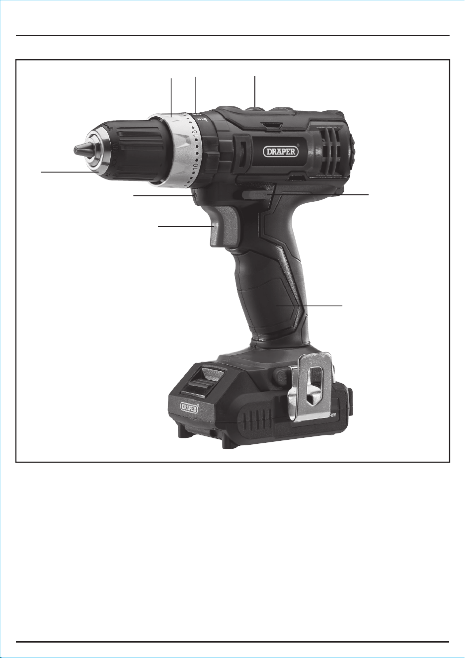
2 Speed selector switch.
Function selector.
Torque selection collar.
10mm Keyless chuck.
LED Worklight.
Variable speed trigger switch.
Forward/reverse selector.
Hand grip.
6. TECHNICAL DESCRIPTION
6.1 IDENTIFICATION
- 11 -
- 12 -
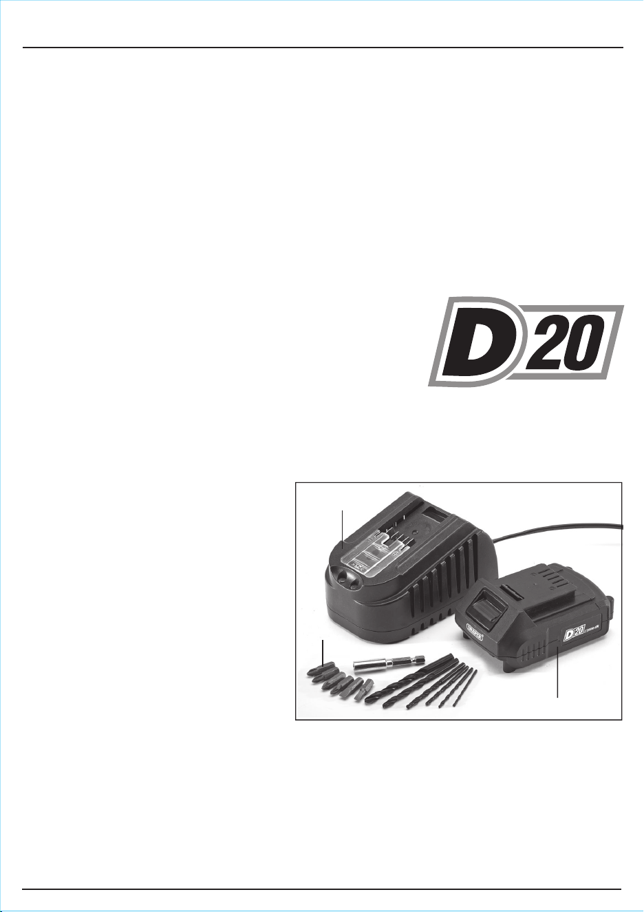
7.3 WHAT’S IN THE BOX
As well as the combi drill, there are
several parts not fitted or attached to it.
1 × 2.0Ah Li-ion battery.
D20 charger.
Accessories.
7. UNPACKING AND CHECKING
7.1 PACKAGING
Carefully remove the product from the packaging and examine it for any sign of damage that may have
happened during shipping. Lay the contents out and check them against the parts shown below. If any
part is damaged or missing, please contact the Draper Help Line (the telephone number appears on
the Title page) and do not attempt to use the product.
The packaging material should be retained at least during the warranty period, in case the machine
needs to be returned for repair.
Warning!
● Some of the packaging materials used may be harmful to children. Do not leave any of these
materials in the reach of children.
● If any of the packaging is to be thrown away, make sure they are disposed of correctly,
according to local regulations.
7.2 D20 MULTI-TOOL INTERCHANGEABLE
BATTERY SYSTEM
The D20 range of tools are a range of tools suitable for
enthusiasts and tradespersons alike, featuring a wide array of
machines all running from the same range of batteries. Many
different capacity batteries are available making sure you can
balance tool weight with longevity and find a battery that meets
your needs. To find out the latest range of accessories including batteries and chargers please consult
the Draper website for more information or to find your local Draper stockist.
MULTI-TOOL BATTERY SYSTEM
- 13 -
8. PREPARING THE DRILL
FIG.1
FIG.2
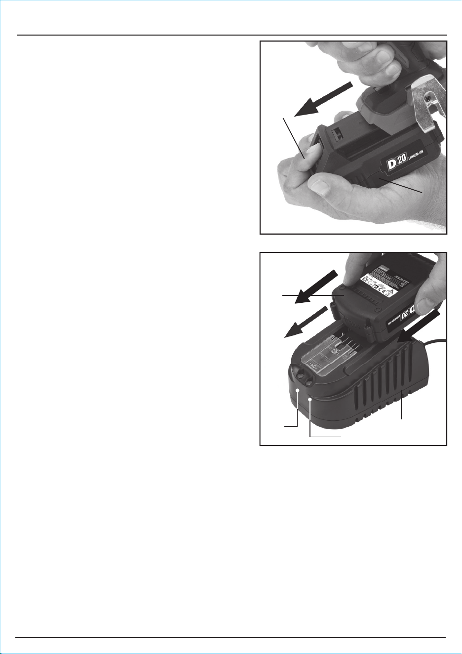
8.1 BATTERY PACK CHARGING –
FIGS.1–2
This power product is either supplied “bare”, without
battery pack or charger (Stock No.55519), or with a
transformer/charger and one battery pack (Stock
No.00594).
Important: Only Draper designated battery packs and
chargers can be used in conjunction with this product.
Use of any other third party battery packs/chargers
with this product is considered misuse and will
invalidate the product’s warranty.
Once connected to the mains supply, recharging of
the battery can be left generally unsupervised,
requiring minimal attention. Complex circuit
construction monitors the battery condition, adjusting
the recharge current to suit. When the recharge cycle
is complete, to maintain the full capacity, a low output
current will continue as required.
Warning! Check the condition of the charger and
battery prior to each charge. If there is any sign of
damage then do not commence charging, seek advice
from Draper Tools.
The battery pack is supplied un-charged and must be
charged before initial use.
To charge the battery pack , it must first be
removed from the tool.
To release the battery pack:
– Press the battery release button and gently
slide the battery pack off (Fig.1).
– Plug the battery charger unit into a 230V/AC
13amp three pin supply socket.
– The red LED will illuminate to show the
charger has power.
– Slide the battery into the charger (the battery is
shaped to fit into the charger one way only.
– After a few seconds delay, the red LED will
flash to show that charging has begun, then
illuminate solid red.
– Whilst the battery is charging, the green LED will flash, (the red LED will go from flashing to
constant red.
– When the battery is fully charged when the green LED stops flashing and remains a constant
green. The red LED will extinguish.
Caution: Do not pull the plug out of the power supply by pulling on the cord. Make sure to grasp the
plug when removing from power supply to avoid damaging the cord.
To remove the battery from the battery charger:
– Supporting the battery charger with hand, pull out the battery from the battery charger.
Caution: If the battery charger has been in continuous use it will be hot. Once the charging has been
completed, leave the charger 15 minutes to cool until next use.
- 14 -
8. PREPARING THE DRILL
If the battery is charged when it is warm due to battery
use or exposure to sunlight, the battery will not be
recharged. In such a case, let the battery cool before
charging.
If the red indicator flickers rapidly at 0.2 second
intervals, check or and remove any foreign objects
in the charger’s battery slot. If there are no foreign
objects, it is probable that the battery or charger is
malfunctioning. Allow battery/charger to normalise
and try again. If a fault remains after trying this then
contact Draper Tools.
8.2 BATTERY PACK PROTECTION
FEATURES
Overcharging protection: This feature that ensures
that the battery pack can never be overcharged.
When the battery pack reaches full charge capacity,
the transformer/charger will automatically shut off,
protecting the internal components from being damaged.
Over-discharging protection: This feature will stop
the battery pack from discharging beyond the
recommended lowest safety voltage.
Overheating protection: The battery pack contains
an internal thermistor cut-off sensor which shuts off
the battery pack should it become too hot during
operation. This can happen if the tool is overloaded or
being used for extended periods. Up to 30 minutes
cooling time may be required, depending on ambient
temperature.
Current protection: Should the battery be
overloaded and the maximum current draw be
exceeded, the battery will shut off to protect the
internal components. The battery pack will resume
working once excessive current draw has returned
to normal, safe level.
Short circuit protection: If, for any reason, the battery pack was to short circuit, the short circuit
protection would immediately stop the battery pack from operating.
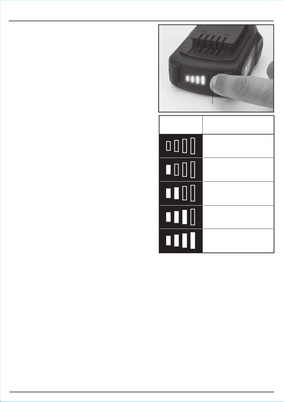
8.3 BATTERY PACK CHARGE STATUS – FIG.3
To display the amount of charge left in the battery pack, press the charge level indicator button
.
8.4 BATTERY LIFE EFFICIENCY AND CHARGING ADVICE
– Avoid recharging at high temperatures.
A rechargeable battery will be hot immediately after use. If such a battery is recharged immediately
after use, its internal chemical substance will deteriorate, and the battery life will be shortened.
Leave the battery and recharge it after it has cooled for a while.
–
The battery should only be used and/or charged when battery temperature is between 5°C and 30°C.
– The battery needs to be warmed-up or cooled down in order to prevent damage to the batteries
internal components,
Note: If battery is too hot or too cold, allow it to ‘normalise’ before use or charging.
Note: Failure to warm up or cool down a battery could result in serious damage to the battery, charger
and user.
Amount of charge
remaining
0 – 10%
10 – 25%
25 – 50%
50 – 75%
75 – 100%
Charge level
indicator
FIG.3
9. BASIC COMBI DRILL OPERATIONS
Warning!
● Dust and swarf
– A correctly fitted dust mask, suitable for the
activity and in accordance to the relevant
standard must be worn.
● Swarf produced by metal drilling is extremely
sharp. Take precautions when clearing swarf.
The burr left on the hole is also sharp and
should be removed with a suitable tool.
● Always wear safety goggles.
● Drill bit will be hot after use.
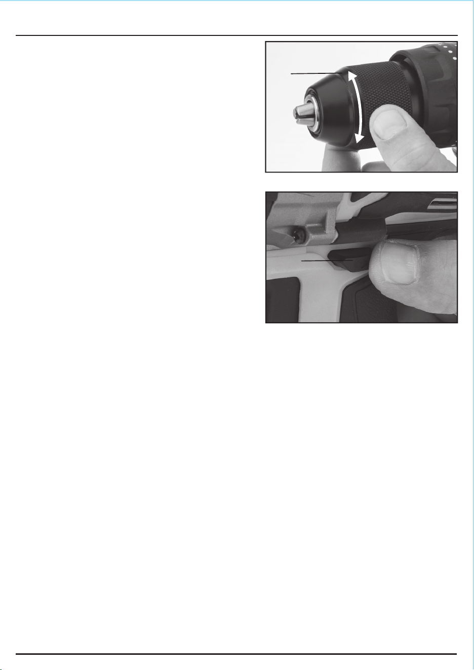
9.1 INSTALLING AND REMOVING BITS
– FIG.1
Note: This product is equipped with an electric
brake.
The drill is fitted with a keyless chuck, this means
that a chuck key is not required to secure the drill or
screwdriver bit.
– Place the drill bit shoulder into the chuck as far
as it will go, making sure not to grip by the
“flute”.
– Tighten the chuck firmly.
Note: Short screwdriver bits need only be inserted
to the depth of the hexagon shank before tightening
chuck by hand.
9.2 ROTATIONAL DRIVE SELECTION – FIG.2
The forward/reverse drive selector switch determines the direction of rotation of the drive,
i.e. clockwise or anticlockwise.
To alter the direction of rotation:
– Stop the machine and push switch to the left or right.
– When the direction switch is pushed to the left, the drive will rotate clockwise.
– When the switch is pushed to the right, the drive will rotate anticlockwise.
– Before operation, check that the switch is set in the required position. Do not change the
direction of rotation until the driver comes to a complete stop.
– When the driver is not in use move the direction switch to the neutral position (the middle
setting) to lock the trigger out.
Note: Failure to use the neutral position may activate the trigger inadvertently. This inadvertent
operation may cause the driver to become damaged.
- 15 -
FIG.1
FIG.2
9. BASIC COMBI DRILL OPERATIONS
- 16 -
FIG.3
FIG.4
FIG.5
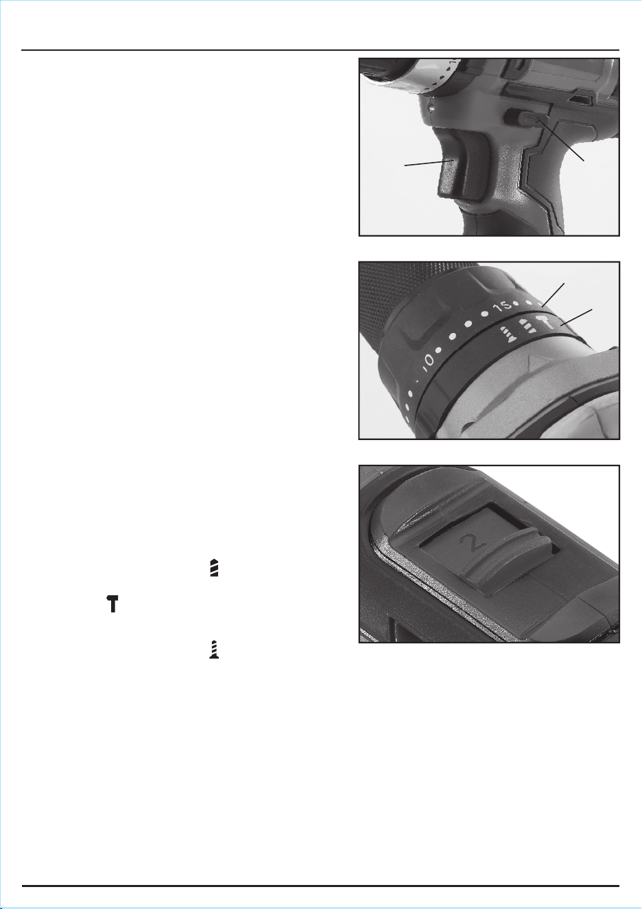
9.3 VARIABLE SPEED TRIGGER – FIG.3
When the trigger is depressed, the drive will
rotate (provided the direction switch is set in the
forward or reverse position). This trigger switch is
electronic which enables the user to vary the speed
continuously.
– The speed varies according to how far the
trigger switch is depressed.
– The further it is depressed, the faster the drive
spindle will rotate.
– The lighter it is depressed, the slower it will
rotate.
9.4 TORQUE SELECTION CONTROL –
FIG.4
By turning the collar it is possible to adjust the
amount of torque.
– Settings 1 – 20 provide a facility for setting the
torque to the required level. For example, this
means that repetitive driving of screws of the
same size will be driven into the material to the
same torque, thus giving the same fixing
strength, or in the case of countersunk screws,
these will all be driven to the same depth in
the material.
– The torque control prevents the heads of small
diameter screws being twisted off when
correctly set.
– By turning the selector it is possible to
switch between rotary drilling, percussion
drilling and screwdriving functions:
– Twist the torque setting to for rotary drilling.
– For the “hammer drill” setting, twist the torque
setting to and the percussion feature will
come into action – this is intended for drilling
into masonry, etc.
– Twist the torque setting to for screwdriving
functions.
9.5 TWO SPEED GEAR BOX – FIG.5
– Select a low gear 1 (slower rotational speed
and higher torque) for screwdriving.
– Use a high gear 2 (faster rotational speed and
lower torque) for drilling holes.
- 17 -
FIG.6
FIG.7
9. BASIC COMBI DRILL OPERATIONS
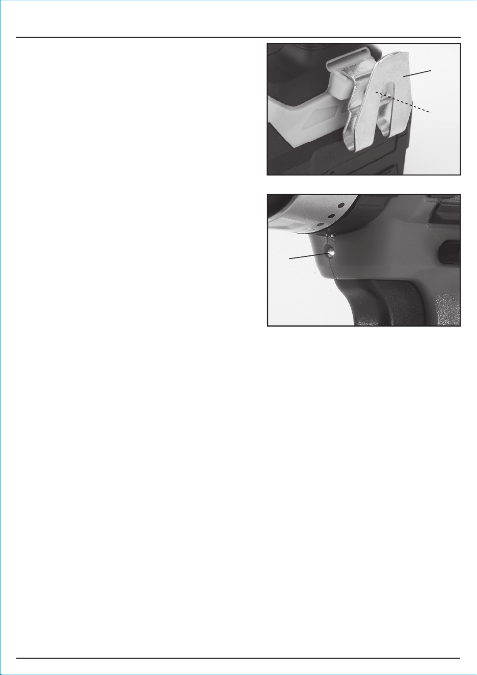
9.6 BELT CLIP – FIG.6
The spring steel belt clip is convenient for
hanging the drill temporarily. The clip can be
installed on either side of the tool.
To install the clip:
– Locate the clip in position and fasten with
screw supplied, take care to not
overtighten and strip the thread.
9.7 LED WORKLIGHT – FIG.7
To aid use in confined, and inadequately lit spaces;
the LED worklight automatically illuminates
when the trigger is activated.
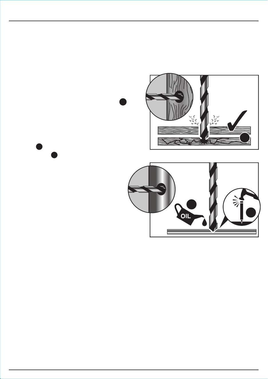
FIG.9
FIG.8
9.9 DRILLING WOOD AND PLASTIC –
FIG.8
To prevent splitting around the drill holes on the
reverse side, clamp a piece of scrap timber
under the material to be drilled.
9.10 DRILLING METAL – FIG.9
Metals such as mild steel, aluminium and brass
may be drilled.
– Mark the point to be drilled with a centre
punch to help the drill bit tip to locate.
– A drop of oil on the drilled area will aid
cutting and help prolong the life of the bit.
Note: Although metal drilling is technically within
the capabilities of this drill, its rotational speed
is not always fast enough to achieve perfect
results every time. For this reason, extra
caution should always be taken when drilling
metal, as snagging of the drill may occur.
9.11 DRILLING MASONRY
Start drilling at a low speed to prevent the drill bit
from wandering. Once penetration is achieved, fully
depress the trigger to achieve maximum speed and
hammer power.
9.8 SCREWDRIVING
To prevent slip or damage to the screw head, match the screwdriver bit to the screw head size.
To remove screws:
– Move the direction switch to the reversing position and apply pressure to the screw head and
depress the trigger slowly).
Screwdriver bits are consumable items.
- 18 -
9. BASIC COMBI DRILL OPERATIONS
B
C
B
C
A
A

- 19 -
10. OPTIONAL ACCESSORIES
10.1 OPTIONAL ACCESSORIES
A full range of accessories are available from Draper Tools.
Please visit our website for details: www.drapertools.com

11.1 MAINTENANCE
Regular inspection and cleaning reduces the necessity for maintenance operations and will keep
your tool in good working condition.
The motor must be correctly ventilated during tool operation. Avoid blocking the air inlets and
vacuum the ventilation slots regularly.
11.2 TROUBLESHOOTING GUIDE
Note: Remove the battery pack before carrying out adjustment, servicing or maintenance.
11. MAINTENANCE & TROUBLESHOOTING
Drill does not operate. – Battery pack no charge.
– Forward/reverse not
selected.
– Battery pack faulty or
damaged.
– Re-charge battery pack.
– Select forward/reverse.
– Replace battery pack.
Motor runs, but slowly/ losing
power.
– Battery pack no charge.
– Battery pack faulty or
damaged.
– Re-charge battery pack.
– Replace battery pack.
Chuck does not close or grip. – Swarf in chuck. – Clean inside of chuck with
cleaning fluid.
Battery pack doesn’t charge /
non-llumination / non
illumination of charger.
– Fuse blown in charger
plug.
– Charger faulty.
– Replace fuse.
– Replace charger.
Problems Possible cause Required action
- 20 -

- 21 -
Li-ion
12. DISPOSAL
12.1 DISPOSAL
– At the end of the machine’s working life, or when it can no longer be repaired, ensure that it is
disposed of according to national regulations.
– Contact your local authority for details of collection schemes in your area.
In all circumstances:
● Do not dispose of power tools with domestic waste.
● Do not incinerate.
● Do not dispose of WEEE* as unsorted municipal waste.
* Waste Electrical & Electronic Equipment.
12.2 BATTERY PACK DISPOSAL INFORMATION
Warning!
● Do not put battery pack in fire or mutilate – cells may burst or release toxic materials.
● Do not short circuit cells, may cause burns.
● The battery pack must be removed from the appliance before it is scrapped.
● The battery pack is to be disposed of safely.
● Do not mutilate batteries, corrosive electrolyte will be released.
● Do not dispose of batteries or cells in a charged condition.
Expired batteries must be recycled/disposed of in accordance with the appropriate regulation or
legislation. They should be returned to your local warranty agent/stockist.
- 22 -
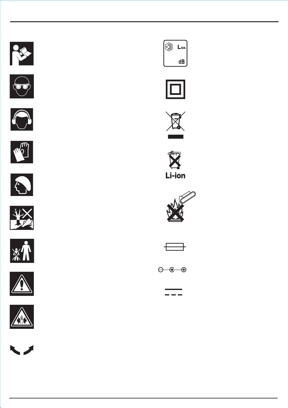
99
Single value noise marking.
(Maximum declared A-Weighted
sound power level in decibels).
13.1 EXPLANATION OF SYMBOLS
13. EXPLANATION OF SYMBOLS
Read the instruction manual.
Wear safety glasses.
Wear ear defenders.
Wear protective gloves.
Long and loose hair must be
contained or securely tied back.
Do not abandon into the
environment.
Keep out of the reach of children.
Direction of rotation.
Warning!
Warning! Risk of crushing.
Lithium-ion product.
WEEE –
Waste Electrical &
Electronic Equipment.
Do not dispose of Waste Electrical
& Electronic Equipment in with
domestic rubbish.
Class II construction
(Double insulated).
Polarity indication.
Rated voltage.
Do not incinerate or
throw onto fire.
Fuse.
130°
+++++
+
+
++++++
+
+++
++++
+++++
+++
+
++
++
+++
+
+++++++

NOTES
- 23 -
©Published by Draper Tools Limited.
No part of this publication may be reproduced, stored in a retrieval system or transmitted in any form or by any means,
electronic, mechanical photocopying, recording or otherwise without prior permission in writing from Draper Tools Ltd.
CONTACTS
YOUR DRAPER STOCKIST
TAPR0721