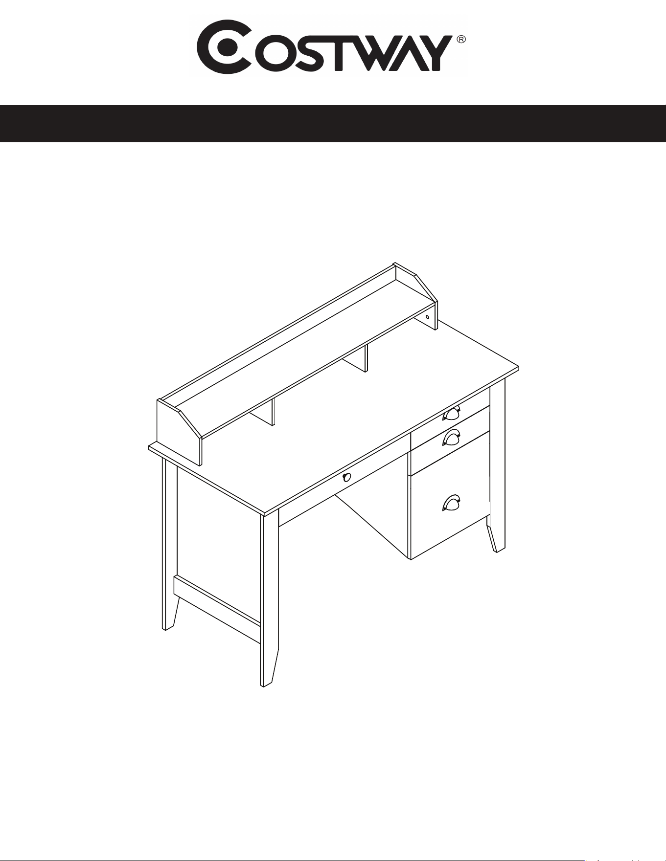
Executive Desk with Hutch
ASSEMBLY INSTRUCTIONS
MODEL HW54474
1 of 15
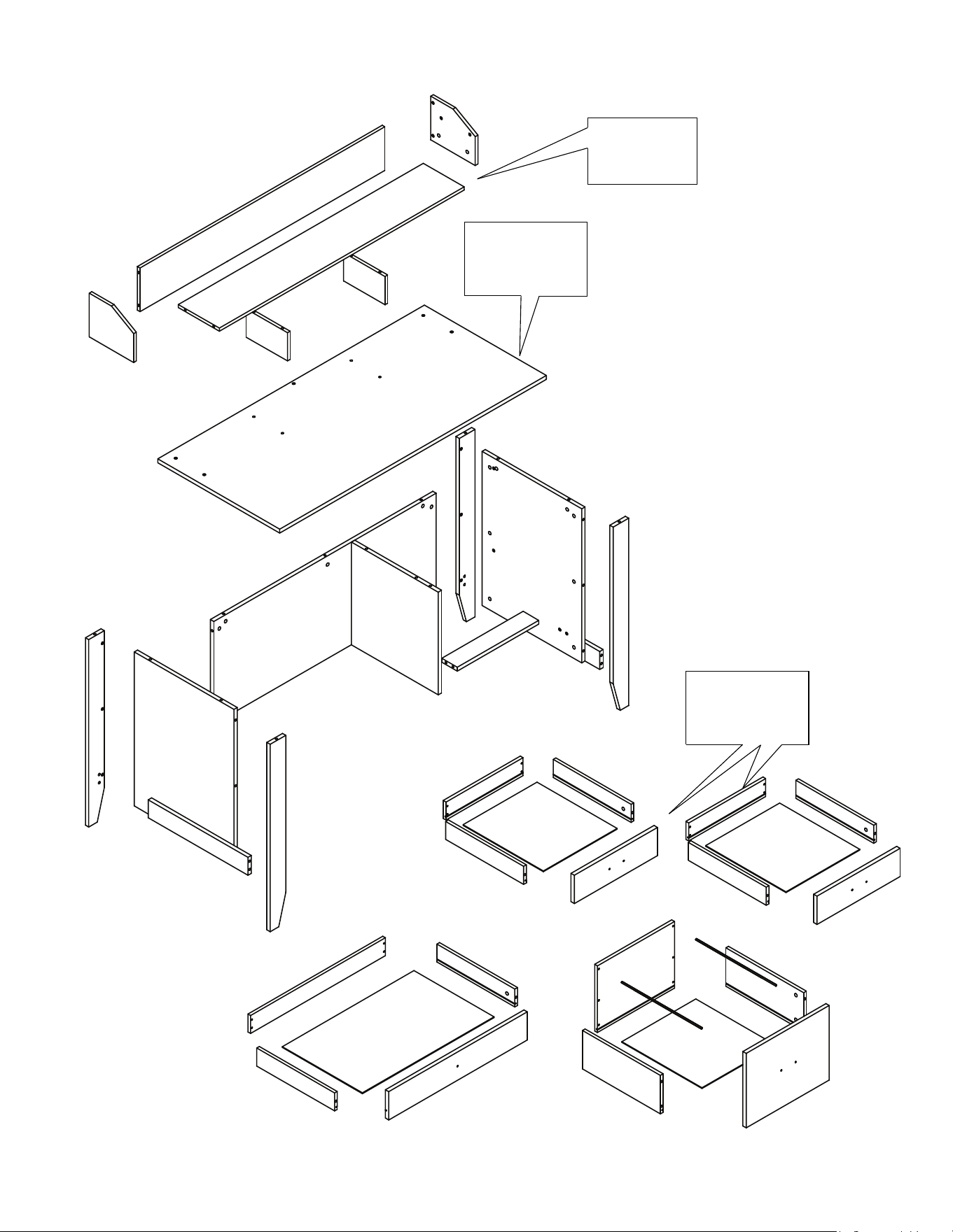
ASSEMBLY OVERVIEW
2 of 15
Desktop maximum
weight capacity
= 132 lbs
Drawers maximum
weight capacity
= 20 lbs
Hutch maximum
weight capacity
= 22 lbs
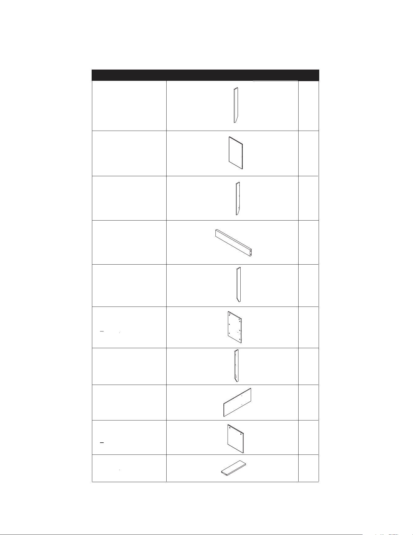
# DESCRIPTION QTY.
1 Left Corner
Board, Front
1
2
Left Board
1
3
Left Corner
Board, Back
1
4
Trim Board 2
5
Right Corner
Board, Front
1
6 Right Board 1
7 Right Corner
Board, Back
1
8 Back Board 1
9
Center Board 1
10
Support Board 1
3 of 15
PARTS LIST 1 OF 3
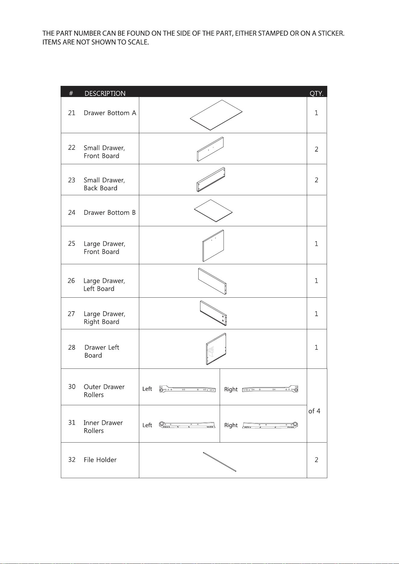
THE PART NUMBER CAN BE FOUND ON THE SIDE OF THE PART, EITHER STAMPED OR ON A STICKER.
ITEMS ARE NOT SHOWN TO SCALE.
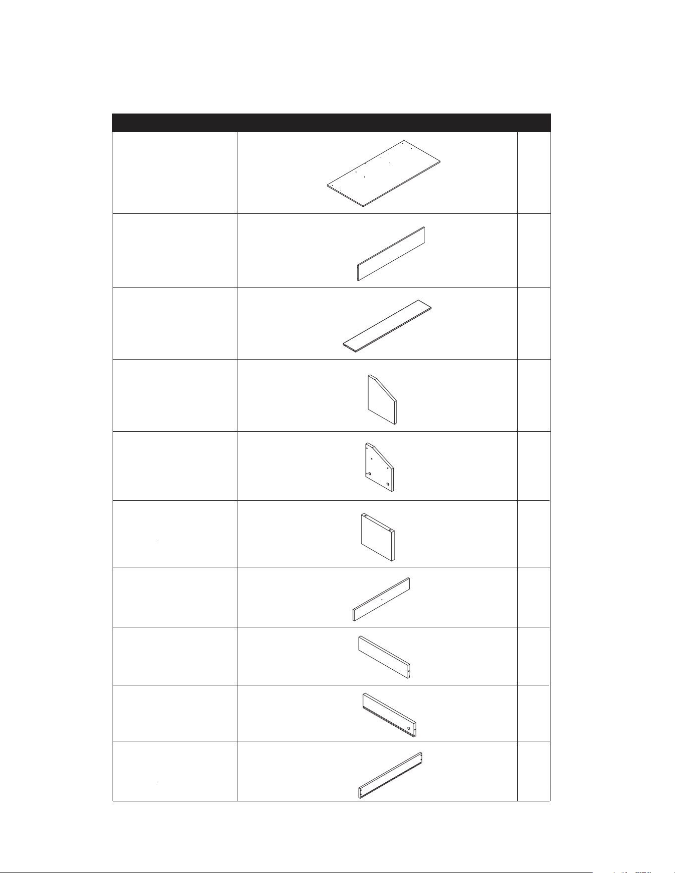
# DESCRIPTION QTY.
11 Desktop 1
12
Hutch Back
1
13
Hutch Shelf 1
14
Hutch Left
Board
1
15
Hutch Right
Board
1
16 Hutch Middle
Board
2
17 Medium Drawer,
Front Board
1
18
Drawer Left
Board
3
19
Drawer Right
Board
3
20
Medium Drawer,
Back Board
1
4 of 15
PARTS LIST 2 OF 3
THE PART NUMBER CAN BE FOUND ON THE SIDE OF THE PART, EITHER STAMPED OR ON A STICKER.
ITEMS ARE NOT SHOWN TO SCALE.
3
4 sets
5 of 15
6 of 15
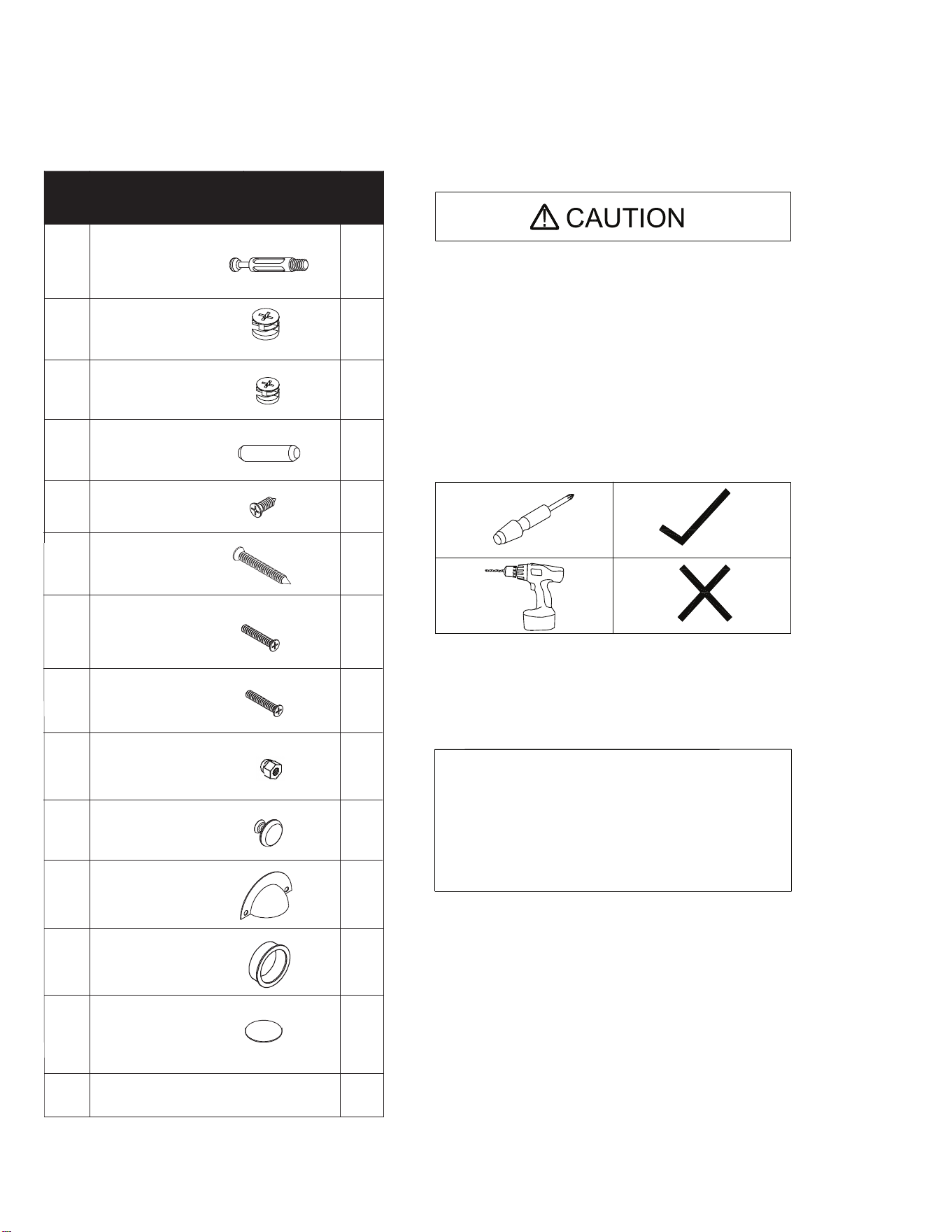
HARDWARE LIST
EXTRA HARDWARE INCLUDED FOR YOUR CONVENIENCE. ITEMS ARE NOT SHOWN TO SCALE.
PART DESCRIPTION
QT
Y.
A Bolt
56
F1
M4 x 22MM 6
I
Plastic Grommet 1
J
Large Handle 3
B2 24
IF YOU ARE MISSING ANY OF THESE PARTS,
OR IF YOU HAVE A DAMAGED PART, PLEASE
VISIT WWW.COMFORTPRODUCTS.NET/SUPPORT
REFERENCE THE MODEL # ON THE FRONT OF
THIS MANUAL. SIMPLY COMPLETE THE INFORMATION,
INCLUDING THE PART YOU NEED. THE PART WILL
NORMALLY BE SHIPPED WITHIN 48 HOURS.
- READ THE INSTRUCTION MANUAL BEFORE ASSEMBLING.
- REMOVE ALL PIECES BEFORE BEGINNING INSTALLATION.
- OPEN THE HARDWARE AS NEEDED .
- ASSEMBLE IN AN AREA WITH PLENTY OF SPACE.
- READ EACH STEP BEFORE BEGINNING CONSTRUCTION.
- HAVE A SCREWDRIVER BEFORE YOU BEGIN ASSEMBLING
(NOT INCLUDED).
- NEVER FORCE THE SCREWS OR FITTINGS.
- KEEP THIS MANUAL FOR FUTURE REFERENCE.
- TIGHTEN ALL THE SCREWS EVERY 6 MONTHS.
CLEANING AND C ARE
- CLEAN SURFACES WITH A DRY OR DAMP CLOTH.
- DO NOT USE ABRASIVE CLEANERS.
- DO NOT USE A POWER DRILL.
C
K
Dowel
Sticker
20
B1 Large Cam
Small Cam
32
D M4 x 14MM
32
E M5 x 40MM
16
F2 M4 x 18MM
1
G Nut
6
H Small Handle
1
24
DX16
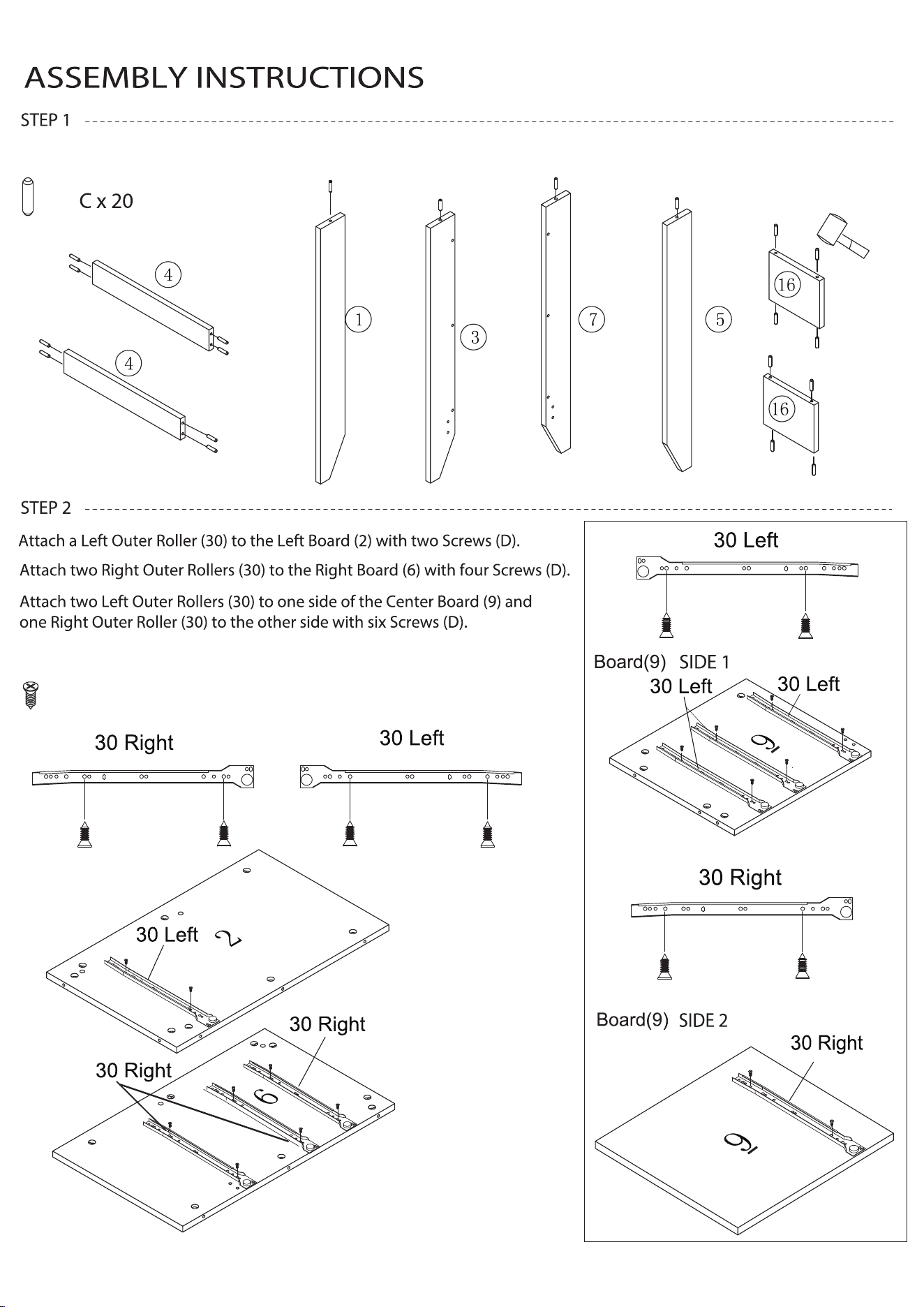
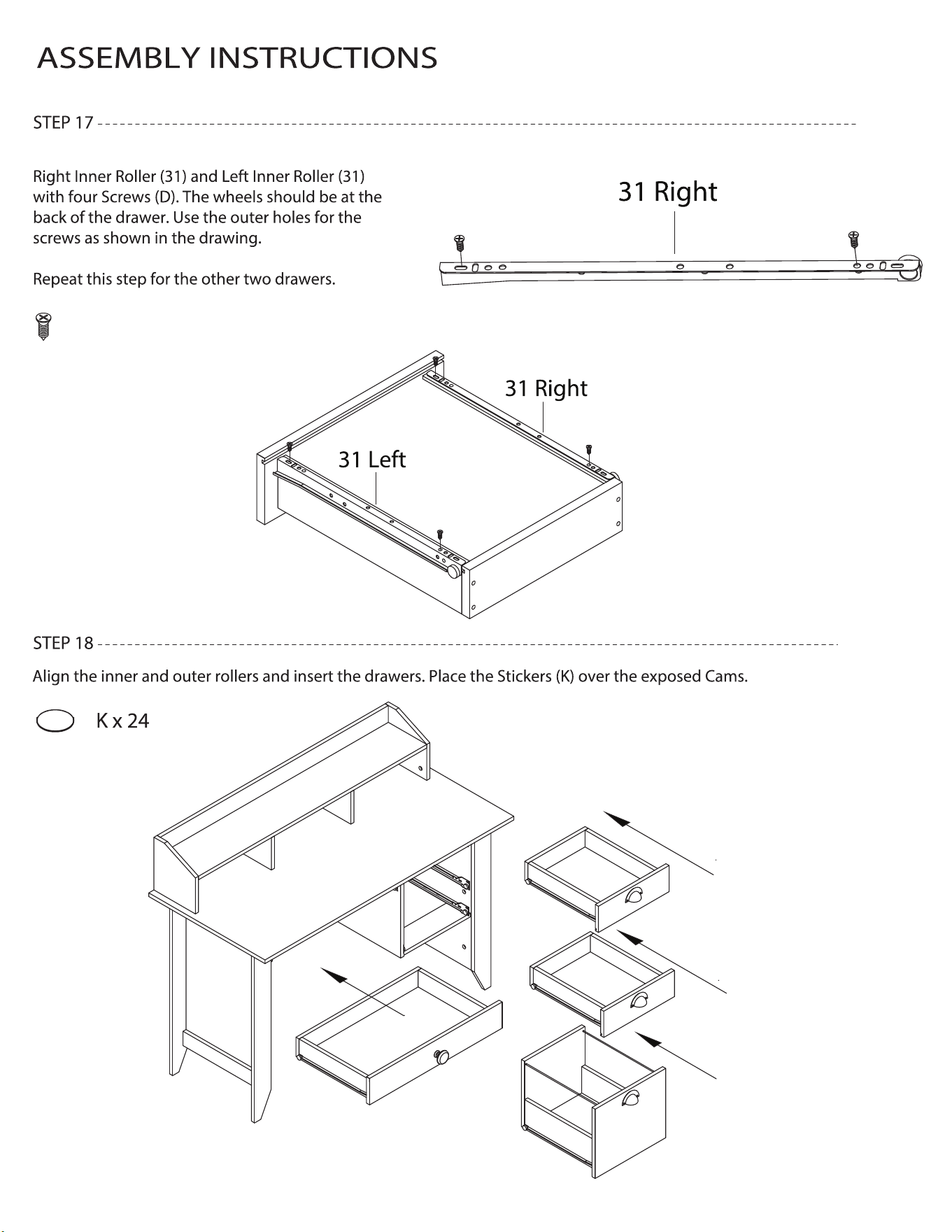
Refer to the drawings for which holes in the rollers to use.
Insert twenty Dowels (C) into the boards shown below.
7 of 15
8 of 15
ASSEMBLY INSTRUCTIONS
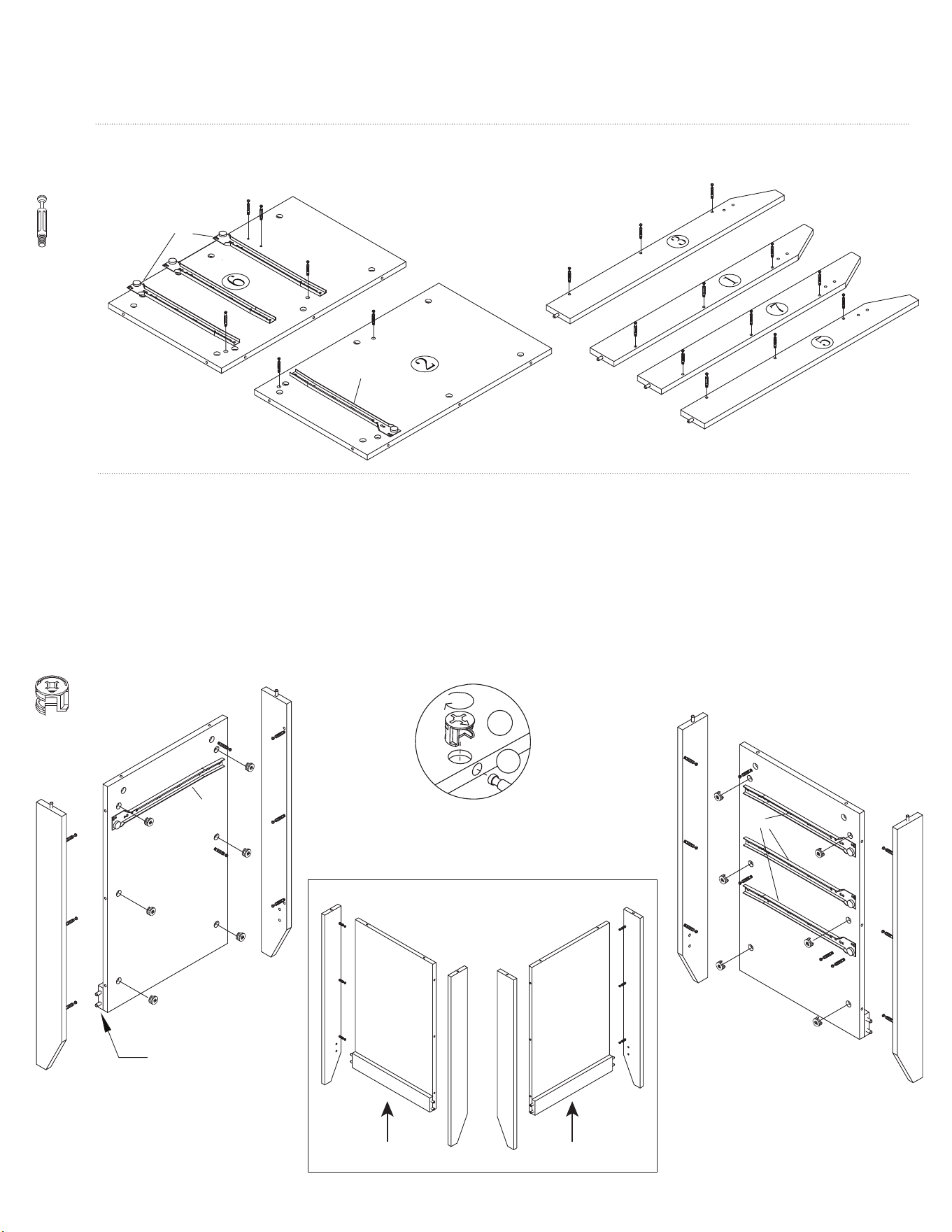
Fix eighteen Bolts (A) to the Boards shown below.
STEP 3
Insert twelve Large Cams (B1) into the Left (2) and Right (6) Boards. Make sure the arrows are pointing toward the holes where
the bolts go in.
Attach the Left Corner Boards, Front (1) and Back (3) to the Left Board (2) and one Trim Board (4) by inserting the
Bolts and turning the Cams clockwise half a turn to lock into place. At the same time, insert the dowels of the Trim Board (4)
into the holes of the Front and Back Boards.
Attach the Right Corner Boards, Front (5) and Back (7) to the Right Board (6) and the other Trim Board (4) in the same way.
STEP 4
30 Right
30 Left
2
1
3
5
6
7
5
6
7
4
30 Left
30 Right
A x 18
B1 x 12
1
2
3
4
4
PLACE PART 4 ON THE
OPPOSITE SIDE
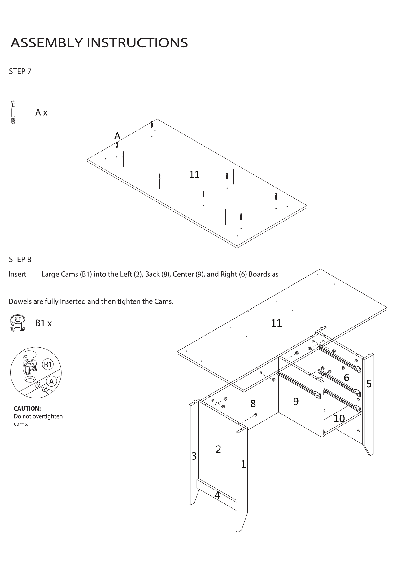
CAUTION:
Do not overtighten
cams.
A
B1
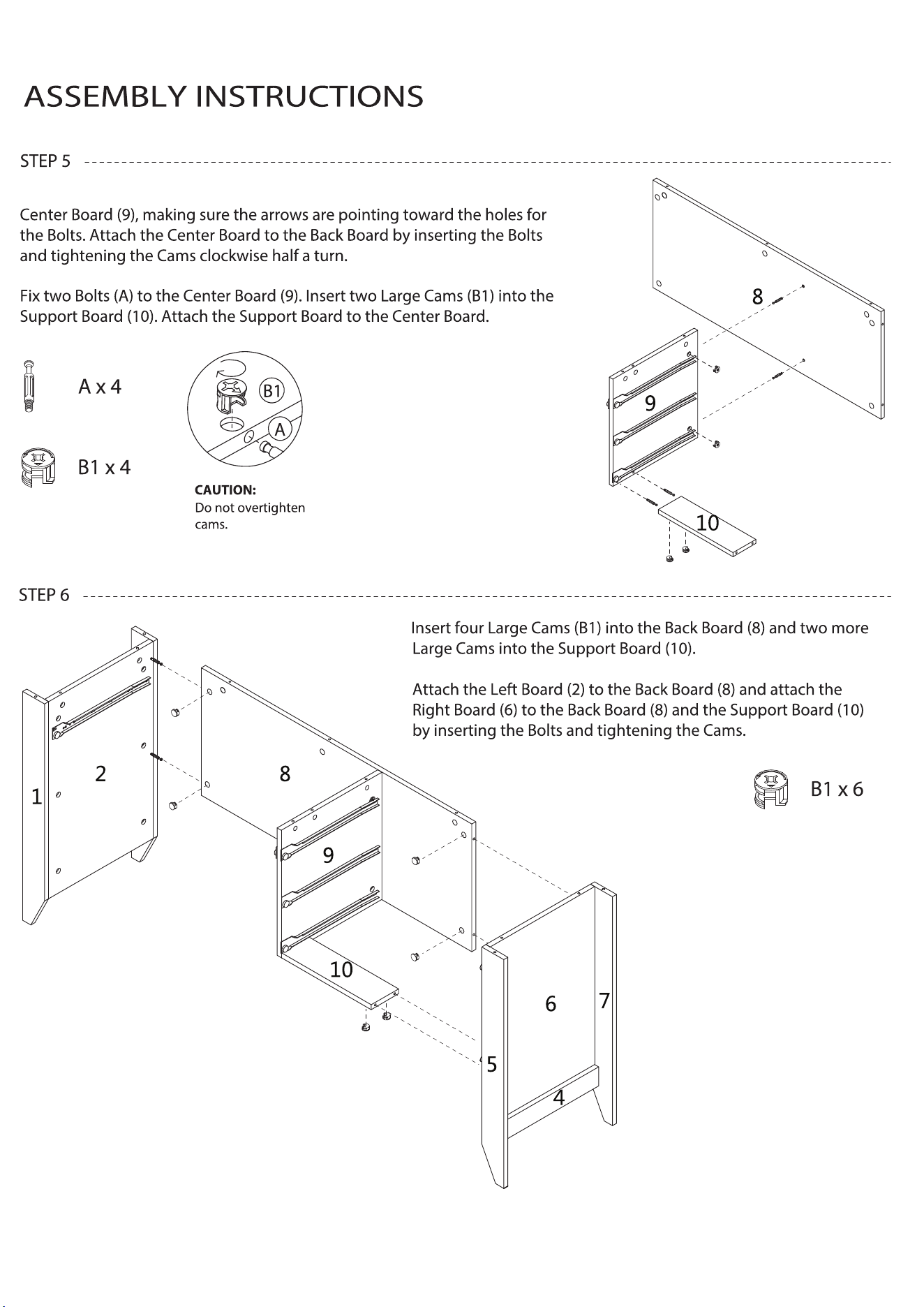
Fix two Bolts (A) to the Back Board (8). Insert two Large Cams (B1) into the
9 of 15
10
10
shown. Align the Bolts in the Desktop (11) with the holes and the Dowels in
the lower part of the desk. Lower the Desktop making sure all Bolts and
Fix ten Bolts (A) to the underside of the Desktop (11).
ten
10 of 15
11 of 15
ASSEMBLY INSTRUCTIONS
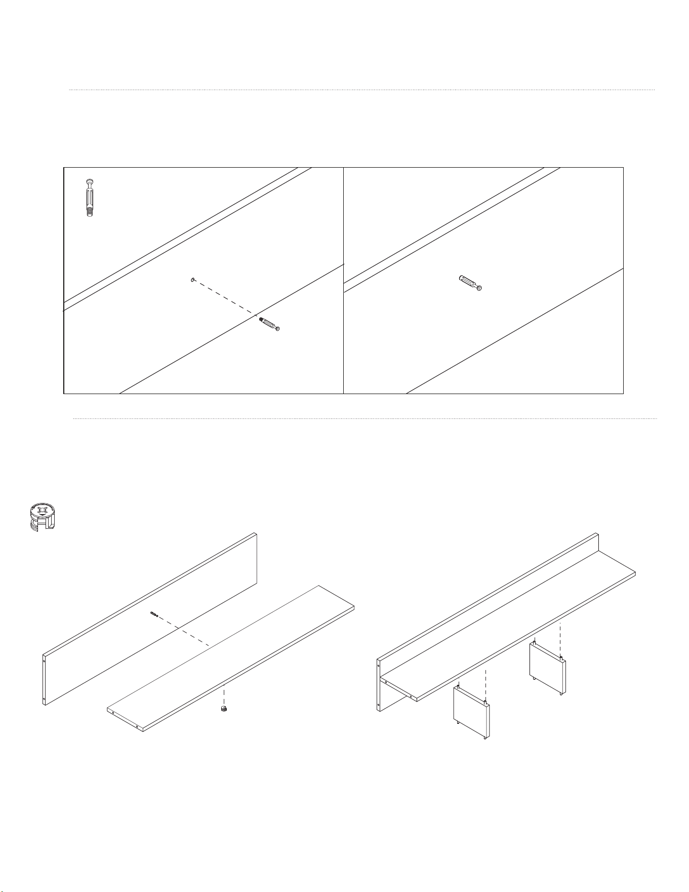
Fix one Bolt (A) to the center of the Hutch Back (12). Insert the Grommet (J) into the round hole.
STEP 9
Insert a Small Cam (B2) into the Hutch Shelf (13). Attach the Hutch Back (12) to the Hutch Shelf by inserting the Bolt and
tightening the Cam. Attach the two Hutch Center Boards (16) to the underside of the Shelf (13) by aligning the Dowels
with the holes and pressing the boards together until tight.
STEP 10
12
12
13
12
13
16
16
B2
A x 1
B2 x 1
12
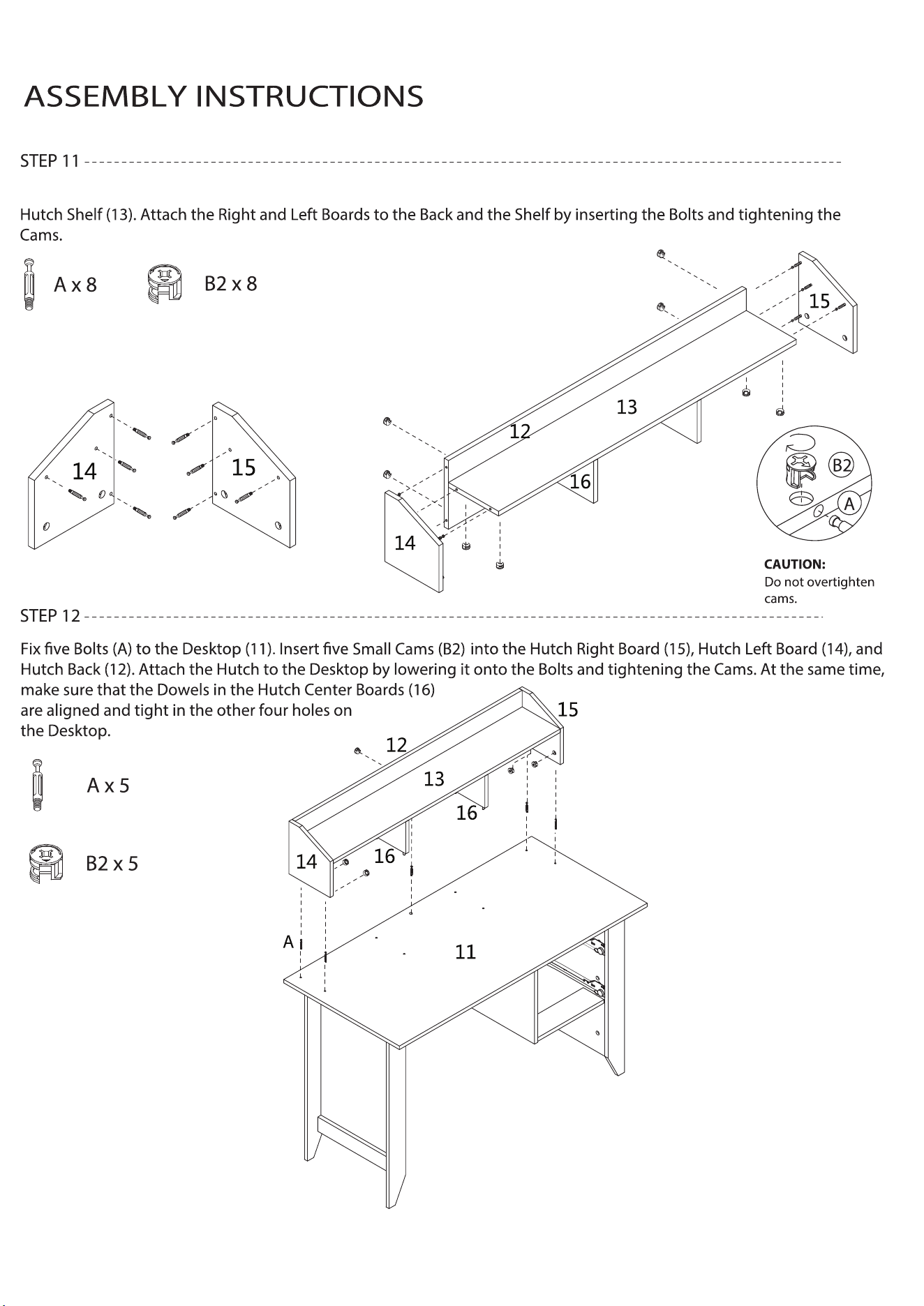
Fix eight Bolts (A) to the Hutch Right (15) and Left (14) Boards. Insert eight Small Cams (B2) into the Hutch Back (12) and
12 of 15
13 of 15
ASSEMBLY INSTRUCTIONS
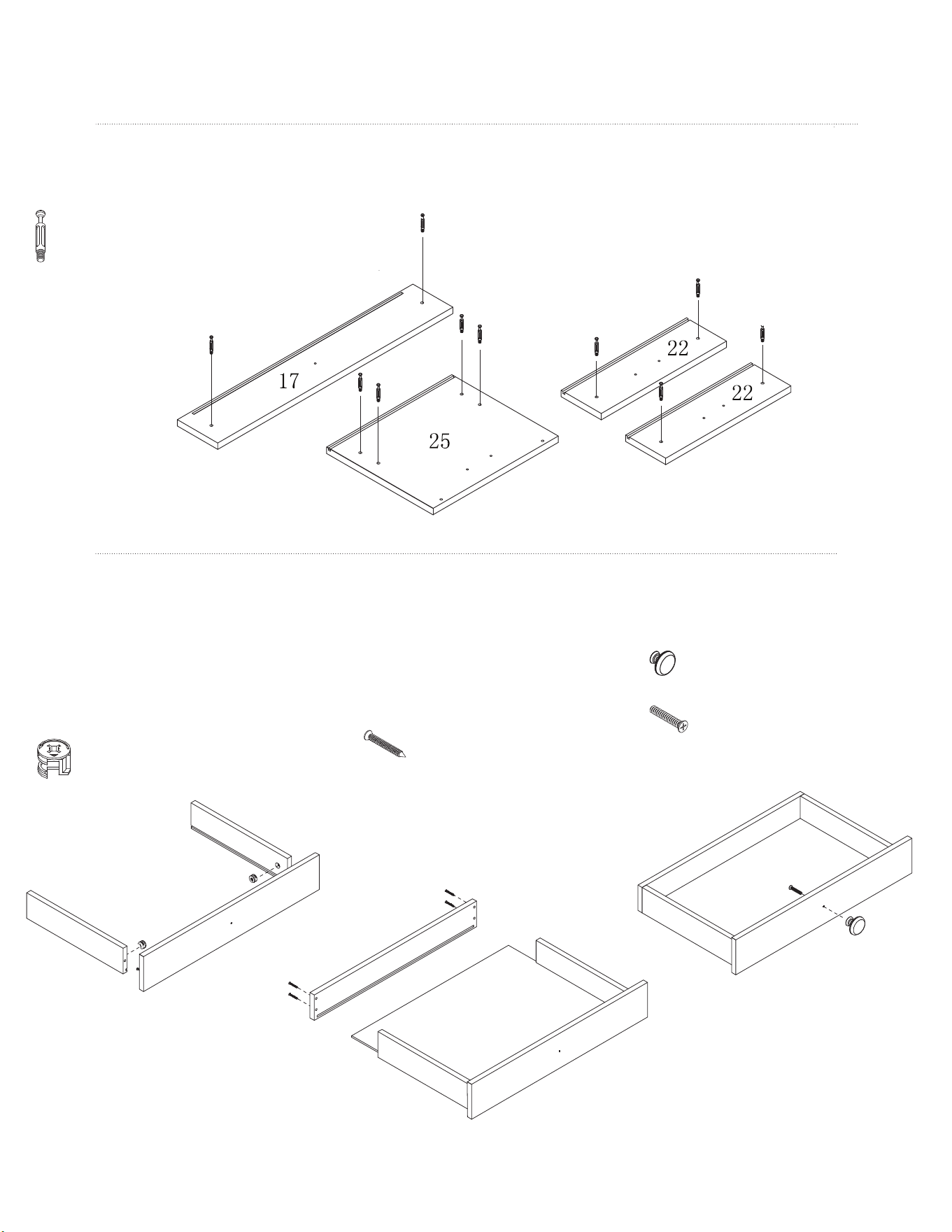
Fix two Bolts (A) to the Medium Drawer Front (17), four Bolts to the
Large Drawer Front (25), and two Bolts to the Small Drawer Front (22).
STEP 13
Insert one Small Cam (B2) into the
Drawer Right Board (19) and one into
the Drawer Left Board (18). Making sure
the grooves are aligned, attach the
Medium Drawer Front (17) to the Right
and Left Boards by inserting the Bolts and
tightening the Cams.
Slide Drawer Bottom A (21) into
the grooves. Align the groove in
the Medium Drawer Back (20) with
the Drawer Bottom and fasten it to
the Right (19) and Left (18) Drawer
Boards using four Screws (E).
Attach the Small Handle (H) to the
Drawer Front (17) using one Screw (F2).
STEP 14
A
18
19
17
20
21
18
19
17
17
A x 10
B2 x 2
H x 1
F2 x 1
E x 4
14 of 15
ASSEMBLY INSTRUCTIONS
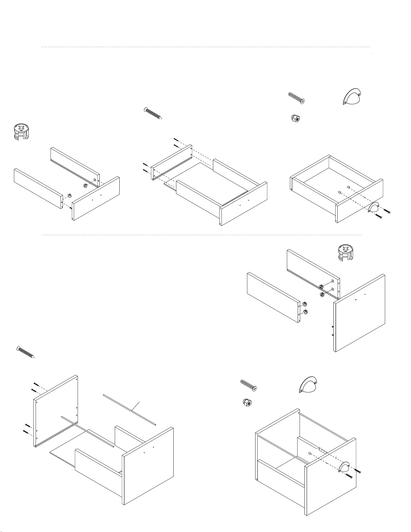
Insert one Small Cam (B2) into the
Drawer Right Board (19) and one
into the Drawer Left Board (18).
Making sure the grooves are aligned,
attach the Small Drawer Front (22) to
the Right and Left Boards by inserting
the Bolts and tightening the Cams.
STEP 15
Insert two Small Cams (B2) into the Large Drawer Right (27) and two into the
Large Drawer Left (26). Making sure the grooves are aligned, attach the
Large Drawer Front (25) to the Right and Left Boards by inserting the Bolts
and tightening the Cams.
Slide Drawer Bottom B (24) into the grooves. Align the groove in the
Large Drawer Back (28) with the Drawer Bottom and fasten it to the
Right (27) and Left (26) Boards using four Screws (E). At the same time,
insert the File Holders (32) into the holes at the top of the Front and
Back Boards.
STEP 16
22
18
19
23
24
22
22
19
18
F1
25
26
27
28
24
32
25
26
27
B2 x 4
G x 2
F1 x 2
B2 x 4
Attach a Large Handle (I) to the Drawer Front (22)
using two Screws (F1) with two Nuts (G).
F1
G
G
G x 4
F1 x 4 I x 2
E x 8
E x 4
Slide Drawer Bottom B (24) into the
grooves. Align the groove in the
Small Drawer Back (23) with the Drawer
Bottom and fasten it to the Right (19)
and Left (18) Boards using four Screws (E).
Attach a Large Handle (I) to the
Drawer Front (22) using two
Screws (F1) with two Nuts (G).
I x 1
DX16
Flip over the assembled drawer and attach a
15 of 15