96 L / 3.4 cu/ft
UGP 3
Portable Propane Refrigerator
OWNER’S GUIDE
serial number:
AUG V2 2023
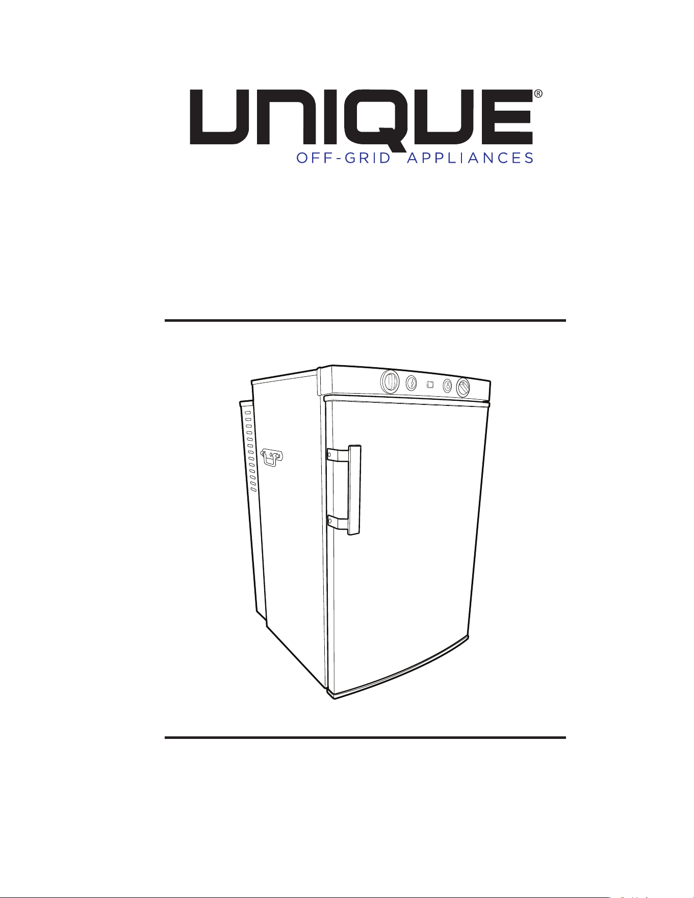
UNIQUE UGP-3
PORTABLE CAMPING REFRIGERATOR
Installation and Owner’s Manual
The installation of the appliance must conform with local codes ANSI
Z21.74 1992, in the absence of local national Fuel Gas Code, ANSI Z233.1,
and in Canada B149.2 Propane Storage and Handling Code
WARNING: Improper installation, adjustment,
alteration, service or maintenance can cause
injury or property damage. Refer to this
manual. For assistance or additional
information consult a qualified installer, service
agency or the gas supplier.
!SAVE THESE INSTRUCTIONS!
FOR YOUR SAFETY IF YOU
SMELL GAS
Open windows.
Do not touch electrical switches.
Extinguish any open flame
Immediately turn off gas supply and
call your gas supplier
Do not store or use gas
oline or other
flammable vapors and liquids in the vicinity
of this or any other appliance
FOR YOUR
SAFETY
If you smell gas:
1. Evacuate enclosure
2. Call professional for help
V5
-2023
FOR YOUR SAFETY
Do not store or use gasoline or
other flammable vapors and
liquids in the vicinity of this or any
other appliance.
WARNING
FIRE OR EXPLOSION HAZARD
If you smell gas:
1. Open windows.
2. Do not attempt to light appliance.
3. Do not touch electrical switches
4. Extinguish any open flame.
5. Shut off fuel supply cylinder valve
or if equipped with a disposable
fuel supply, disconnect the fuel
cylinder from the refrigerator.
6. Evacuate the area immediately
and wait for gas to dissipate such
that you can no longer smell the
gas. If necessary, have the
appliance serviced.
Failure to follow these instructions
could result in fire or explosion, which
could cause property damage,
personal injury, or death.
MANUFAC TUR ED AN D C ERT IFIED B Y
Unique Appliances Ltd
2245 Wyecroft Road
Oakville, Ontario Canada L6L 5L7
Ph: 905-827-6154 Toll Free: 1-877-427-2266
Fax: 905-827-2027 www.UniqueAppliances.com
E-mail: info@UniqueAppliances.com

Table of Contents
Chapters
Welcome 1
Safety and Warnings 2
Appliances Installation/ Operating Instructions 3
Maintenance & Service
13
Troubleshooting & Suggested Spares 17
Door Removal and Reversal and Heating Element
Replacement 19
Temperature Controls & Food Storage and
Cleaning
23
Wiring Diagram
26
Parts & Warranty 30

UNIQUE UGP 3
1
Welcome &
Congratulations
ongratulations on your purchase of a UNIQUE refrigerator!. We are very proud
of our product and we are completely committed to providing you with the best
service possible. Your satisfaction is our #1 priority. Please read this manual very
carefully. It contains valuable information on how to properly maintain your new gas
refrigerator.
We know you will enjoy your new refrigerator and thank you for choosing one of our
Unique Gas Products. We hope you will consider us for future purchases.
PLEASE READ AND SAVE THESE INSTRUCTIONS
This manual provides specific operation instructions for your model. Use your
refrigerator only as instructed in this manual. These instructions are not meant to cover
every possible condition and situation that may occur. Common sense and caution must
be practiced when installing, operating and maintaining the appliance
Please record your model and serial # shown below for future reference. This
information is found on your CSA rating/serial plate on the back of the refrigerator.
Please mail in the Warranty Registration Card included with your refrigerator.
Chapter
1
C
UNIQUE UGP 3
2
Safety and Warnings
If you smell gas
Open windows
Don’t touch electrical switches
Extinguish any open flame
Immediately call your gas supplier
For your Safety
Do not store or use gasoline or other flammable vapors and liquids in the vicinity
of this unit or any other appliance.
Warning
Improper installation, adjustment, alteration, service or maintenance can cause
injury or property damage. Refer to this manual. For assistance or additional
information consult a qualified installer, service agency or the gas supplier.
This product can produce Carbon Monoxide. Carbon Monoxide has no odour
and can kill you. The burner and flue system must be kept clean. See owner’s
manual for cleaning instructions.
Electrical Grounding Instructions: This appliance is equipped with a three-prong
(grounding) plug for your protection against shock hazards and should be plugged
directly into a properly grounded three-prong receptacle. Do not cut or remove the
grounding prong from this plug
Provide ample ventilation, especially when sleeping. This refrigerator “consumes
air (oxygen). Do not use this refrigerator in unventilated structures to avoid
endangering your life. Provide additional ventilation for any additional fuel-burning
appliances and additional “occupants.”
CAUTION: NEVER bring a refillable LP-Gas Cylinder Exceeding 1lb
indoors. A fire or explosion can occur causing property damage,
serious injury or death.
Installation Instructions
The installation of the appliance must conform ANSI Z21.74 1992 in the
absence of local national Fuel Gas Code, ANSI Z233.1, and in Canada B149.2
Propane Storage and Handling Code
UNIQUE UGP 3
3
Installation and Operating Instructions
Installation
For best performance at high ambient temperatures, there must be free air
circulation over the cooling unit at the rear of the refrigerator.
Ensure that there is a free air space above the refrigerator and that the flue (chimney)
on top of the cabinet is not covered in any way. Do not place the refrigerator in a
space where air circulation is restricted. Follow “clearance” instructions.
This UNIQUE 3 appliance has been certified as a portable camping appliance in North
America it must be used as a portable camping appliance for use outdoors in sheltered
area. While using on electrical operation this unit can be used in an enclosed area but
must still be protected from moisture as comply with all clearances.
For installation, for maintaining proper clearances from combustible material to the
refrigerator, the following minimum clearance must be observed:
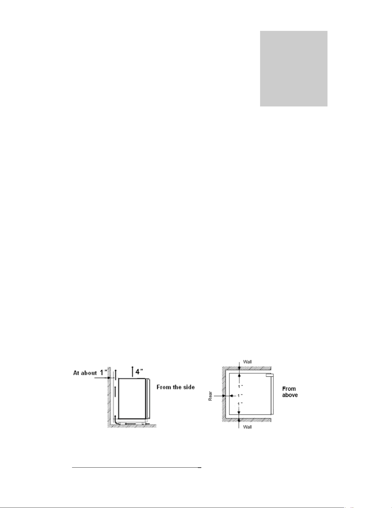
Clearances
Minimum clearances to combustible materials are:
Top – 4”
Sides – 1”
Rear – 1”
Chapter
2
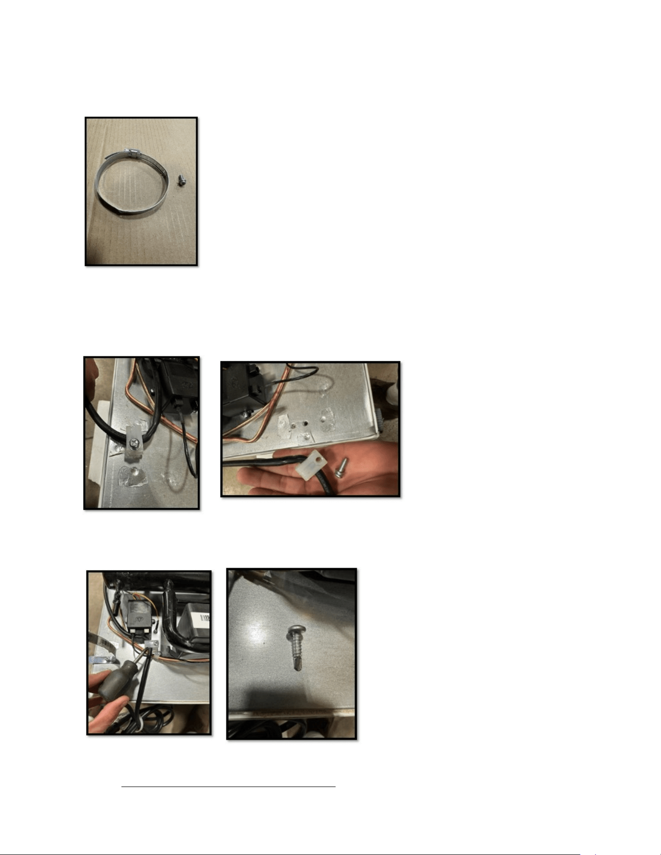
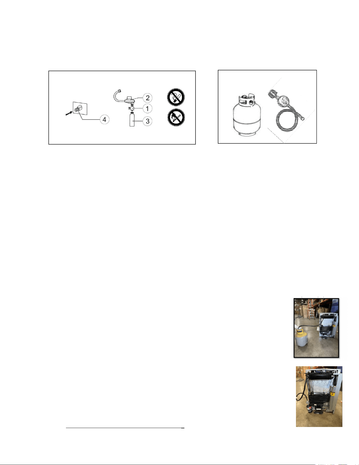
Part Supplied
Note: Steps to this point will be completed at factory (instruction for CSA sample)
Notice 431 Tank Holder Installation Instructions For UGP - 3
Instructions on Installation
1. Locate power cord mount clip at the back of the appliance and remove by loosening 1 phillips head bolt.
2. Relocate clip to area shown in photograph below, and mount with self tapping screw.
4
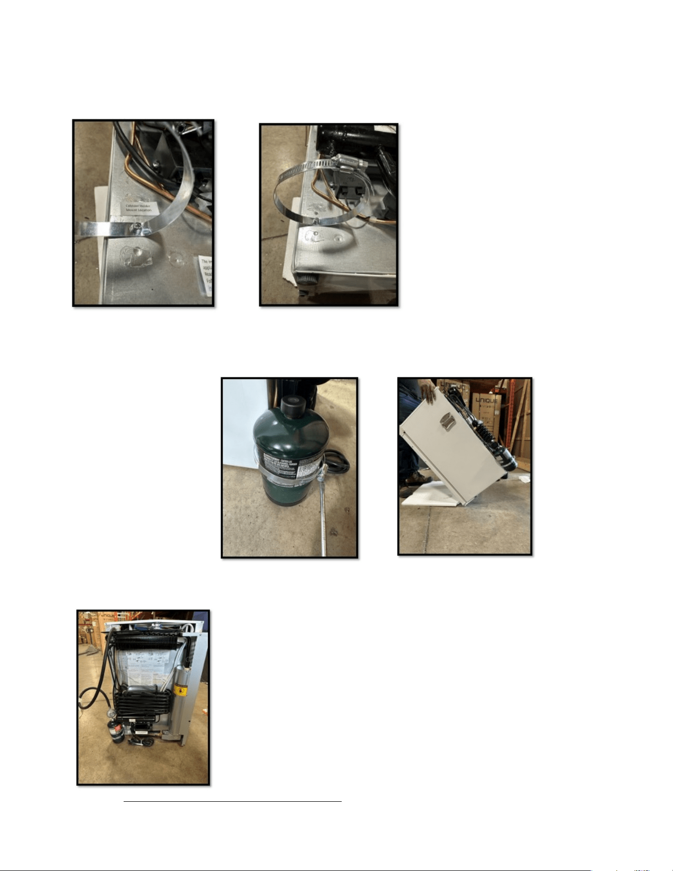
6. Install the hose clamp by using the bolt taken out of the power cord clip, and utilizing the hole the
power clip was originally mounted to. Please note the hose clamp is predrilled with a mount hole.
5
7. Insert tank into hose clamp and tighten until snug. Tank should not fall out of holder when fridge
is tipped forward.
8. Full set up with regulator attached.
UNIQUE UGP 3
6
Note: DO NOT install the appliance directly on carpeting. Carpeting must be
removed or protected by a metal or wood panel beneath the appliance, which
extends at least the full width and depth of the appliance.
Keep appliance area clear and free from combustible materials, gasoline and other
liquids with flammable vapors.
WARNING – DO NOT USE FLAME TO CHECK FOR GAS LEAKS
Levelling
Ensure the fridge is leveled by using a 2ft level; the operation of this unit uses an
absorption system which requires the appliance to be level in order to operate
effectively.
Connecting to Gas Cylinder Types
A. Indoor and Outdoor use
This applies to self-contained fuel supplies and using fuel cylinders of not more than
75 cubic inches (1230 cm3) (2
1/2
pounds nominal water capacity). Fuel supplies shall
be in accordance with the Standard for the Storage and Handling of Liquefied
Petroleum Gases, ANSI/NFPA No. 58. The gas supply inlet to a refrigerator is
fitted with a nipple and nut conforming with the nipple and nut assembly of
Connection No. 600 which will hook directly to your portable camping tank.
B. Option – Outdoor use only
The freezer is designed for a 20# steel propane self-contained fuel cylinder of not
more 4.6 gal (20lbs) capacity. The cylinder(s) must be constructed and marked in
accordance with the specifications for LP-gas cylinders of the U.S. Department of
Transportation, DOT SPEC. 39 (49CFR 178.65). This cylinder must be used
outdoors in accordance with B149.2-10 Storage and Handling Code.
UNIQUE UGP 3
7
B. Option - Outdoor use only
Connecting of Gas Supply
A. Indoor and Outdoor use only
1. Use supplied #600 connector, regulator and hose to connect your appliance to the
gas supply #3.
2. Tighten #3 to #600 regulator assembly
3. and #4 using a backup wrench to the appliance.
4. After connecting, all
gas connections must be checked for leaks
. For this, put
a soapy solution on all gas connections, turn on the gas cylinder manual valve and
watch for bubbles. Never use an open flame to check for leaks.
Note: The gas supply system must incorporate a pressure regulator to maintain a supply
pressure of not more than 12” water column and no less than 11” water column. (Max
setting)
B. Outdoor use only
5. Use optional or supplied regulator and hose to connect your appliance to the gas
supply.
6. Hook up the 5/8”-18UNF connection to the back of your appliance using a
backup wrench.
7. Attach the regulator cap to the tank inlet connection and ensure it is tight.
8. After connecting, all
gas connections must be checked for leaks
. For this, put
a soapy solution on all gas connections, turn on the gas cylinder manual valve and
watch for bubbles. Never use an open flame to check for leaks.
Note: The gas supply system V5-2023must incorporate a pressure regulator to
maintain a supply pre
ssure of not more than 13” water column and no less than 11”
water column. (Max setting)
A.
–
Indoor and Outdoor us
e
· The cylinder be disconnected when the appliance is not in use
·The gas must be turned off at the supply cylinder. Storage of an appliance indoors is permissible only if the
cylinder is disconnected and removed from the appliance. Cylinders must be stored outdoors out
· The cylinder supply system must be arranged for vapor withdrawal
· If in excess of 1 lb (0.45 kg) of liquid fuel capacity, must include a collar to protect the cylinder valve
· So not store a spare LP gas cylinder under or near this appliance
· Never fill the cylinder beyond 80 percent full
· If the instructions in l(i) and l(ii) are not followed exactly, a fire causing death or serious injury may occur;
UNIQUE UGP 3
8
General Operating Instructions
Importance of Leveling a Refrigerator
The refrigerator must be adjusted to a vertical position in both directions. In an
absorption refrigeration system, ammonia is liquefied in the finned condenser coil at the
top rear of the refrigerator. The liquid ammonia then flows into the Evaporator (inside
the freezer section) and is exposed to circulating flow of hydrogen gas, which causes the
ammonia to evaporate, creating a cold condition in the freezer.
When starting this refrigerator, the cooling cycle may require 6 to 8 hours of running time
to begin cooling before the cooling unit is fully operational, you can then begin slowly
loading the compartment.
The tubing in the evaporator section is specifically sloped to provide a continuous
movement of liquid ammonia, flowing downward by gravity through this section. If the
refrigerator is operated when not level, liquid ammonia will accumulate in sections of the
evaporator tubing. This will slow the circulation of hydrogen and ammonia gas, or in
severe cases, completely block it, resulting in a loss of cooling. Warranty will not cover
recharge/rebuild if caused by not running the fridge level.
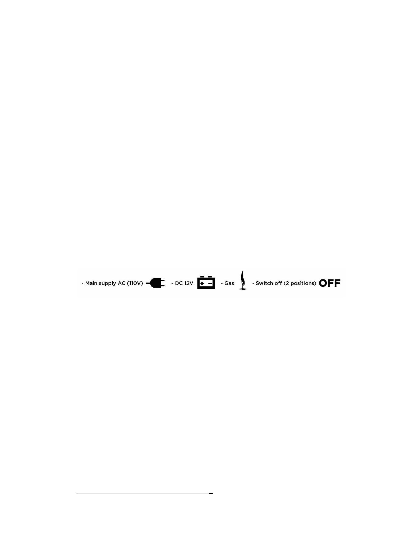
This refrigerator operates LP Gas (Propane), 110V (Electricity)
and 12V DC
The power selector has 5 positions
Gas Operation
“Start Up” Procedure
After initial installation, servicing, or changing gas cylinders etc., the gas pipes may
contain some air which should be allowed to escape by briefly turning on the
refrigerator. This will ensure that the flame lights immediately.
1. Make sure that all valves between the gas container and the refrigerator are
open.
2. Turn selector switch (A) to gas.
3. Depress the safety device control (D) and hold it down while immediately
depressing the electronic igniter button (B)
4. Once the flame indicator (C) starts to move into the green, release the
electronic igniter button (B) but continue to keep the safety device control
(D) depressed for a further 10-15 seconds.

UNIQUE UGP 3
9
5. Release the safety device control (D) and again check to see that the flame is
alight, making sure the needle is in the green area of the flame indicator.
6. Adjust the thermostat knob (E) to desired temperature setting and allow for
6 to 8 hours of operation to achieve desired temperature.
Shut Down Procedure – LP Gas
1. To terminate gas operation, turn selector switch (A) to either OFF or AC (110V)
position.
2. Shut the gas off at the LP-gas supply cylinder when the appliance is not in use.
3. If the refrigerator will not be in operation for a period of weeks, it should be emptied,
defrosted, cleaned and the doors left open. The ice tray should also be dried and kept
outside the cabinet.
110V Operation
1. Make sure that the gas valve is turned off at the tank.
2. Ensure the electrical cord is plugged into a grounded outlet
3. Turn the selector switch (A) to AC (110V) position.
4. Adjust the thermostat knob (E) to desired temperature setting and allow for 6 to
8 hours of operation to achieve desired temperature.
12V DC Operation
Set the power selector knob (A) to DC mode. See right fig. The DC mode is only designed to be
used when driving, otherwise your battery will be discharged within a few hours!
On 12V DC operation the fridge will only maintain temperature already achieved. .
1. If 110 Volts or LP gas is not available, the refrigerator can work with DC12V
(3-Way models only).
2. Make sure that you turn the main power switch (A) to AC (110V) position.
This will allow the heating element to work, you can then connect the
12VDC power cord (not supplied) to the terminal block located at the upper
right side of the refrigerator, while facing the back.
3. DC operation is not as efficient as LP Gas or AC operation. DC electric
should not be used to initially cool the refrigerator. Only use DC when the
other modes are unavailable (for example; while in transit). When you start to
use AC or gas supply, make sure that you disconnect the DC power input.
UNIQUE UGP 3
10
4. To terminate any power mode, gas, AC or DC, turn the knob (A) to either of
two OFF positions
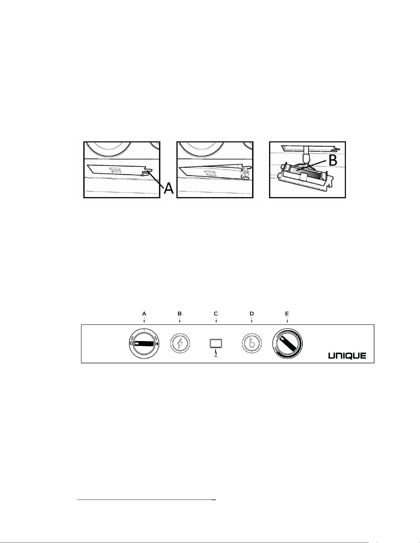
Battery replacement for electronic spark ignition
When the battery ignition fails to spark, you need to replace the battery, replacement step
as follows
1. Hold and pull down the “A” as illustrated in pic, take out the battery box.
2. Replace the old AAA battery “B” with new one. Note: 7#1.5V battery need to be used
and the red wire must connect to the “+” side of the battery.
CONTROLS – See Fig. #1 for description of controls
Figure #1
Thermostat
The refrigerator cooling temperature is controlled by a combination thermostat that can
be adjusted by turning knob E to different settings to maintain the desired refrigerator
temperature when operating on either gas or 110V. Knob D also incorporates a safety
device which automatically shuts off the supply of gas if the flame goes out. The
electronic igniter discharges sparks onto the burner when the button is pushed.

UNIQUE UGP 3
11
1. “DEF” Defrost setting on the Gas/Electric Thermostat: In gas operation, the
thermostat closes its main valve and the burner runs continuously at the bypass rate or
pilot flame. (turn fully counter clockwise), and in 110V operation the element will cycle
off, until cooling is again required.
2. “MAX” Setting of the Thermostat: In gas operation, the thermostat allows the
burner to remain on high flame continuously. (turn clockwise), and in 110V operation the
element will stay on until the desired temperature is reached inside the fridge.
3. The thermostat can be adjusted between “Max” and “Warm” to obtain the desired
fridge temperature. When the thermostat reaches the set temperature, it will reduce the
burner back to bypass operation or shut the element off in 110V operation.
4. In DC operation the fridge will only maintain the temperature that’s already been
achieved. There is no thermostatic function.
When operating on 110V or LP gas, the setting of the thermostat is critical and
recommend it be adjusted to maintain a dry frost on the cooling fins (approx. 38
Fahrenheit or 3 Celsius). Adjust the thermostat knob closer to “Max” (clockwise) when
the ambient temperature rises.
How to Use the Refrigerator
FOOD STORAGE COMPARTMENT
The food storage compartment is completely closed and unventilated, this is necessary to
maintain the required low temperature for food storage. The coldest areas in the
refrigerator are under the cooling fins and at the bottom of the refrigerator. The warmer
areas are on the upper door shelves. This should be considered when placing different
types of food in the refrigerator.
FROZEN FOOD STORAGE COMPARTMENT
This compartment is not designed for deep or quick freezing of food. Meat or fish,
whether raw or prepared, can be stored in the frozen food storage compartment provided
they are pre-cooled in the refrigerator. To prevent food from drying out, keep it in
covered dishes, containers, plastic bags or wrapped in aluminum foil.
Defrosting
Frost will gradually accumulate inside the refrigerator and freezer surfaces. It must not be
allowed to grow too thick as it acts as an insulator and adversely affects the refrigerator
UNIQUE UGP 3
12
performance. Check the formation of frost every week and when it exceeds ½” thick,
defrost the refrigerator.
Shut off and empty the refrigerator, leaving the fridge and the freezer doors open.
Defrosting time can be reduced by filling the ice tray with hot water and placing it in the
freezer compartment.
DO NOT USE A HOT AIR BLOWER, PERMANENT DAMAGE
COULD RESULT
. DO NOT USE A KNIFE, ICE PICK, OR ANY
OTHER SHARP TOOLS TO REMOVE FROST FROM THE FREEZER
COMPARTMENT
.
FRIDGE SECTION
Inside the refrigerator compartment, the defrost water drips into a catch tray and moves
to the back of the fridge via a small tube. If heavy frost has built up on the cooling fins
creating a lot of defrost water, your water reservoir may overflow, we suggest you inspect
reservoir before/after cycle.
F
REEZER SECTION
This area must be wiped down with cloths to remove water after defrosting; there is no
catch tray for this compartment
When all frost is melted in the freezer compartment & interior of the refrigerator it should
be wiped up with a clean cloth. Replace all food and set the thermostat to its normal
position.
Cleaning
Cleaning the refrigerator is usually done after it is defrosted or put into storage. To clean
the interior liner of the refrigerator, use a lukewarm water and weak soda solution. Use
only warm water to clean the finned evaporator, gasket, ice trays and shelves.
Never use strong chemicals or abrasives to clean these parts as the
protective surfaces will be damaged. It is important to always keep the
refrigerator clean. Dishwasher detergent is recommended

UNIQUE UGP 3
13
Maintenance & Service
The user should be aware of service that must be done on a regular schedule to keep the
refrigerator operating properly. Installation must be by a licensed gas fitter in accordance
with local codes or must comply with Propane Installation Code CAN/CGA-B149.2
(latest edition)
Keep appliance area clear and free from combustible materials, gasoline and other
liquids with flammable vapors.
Do not obstruct the flow of combustion and ventilation air, ensure clearances are
followed.
REFRIGERATOR REMOVAL
Before working on the refrigerator, shut off the gas supply. Disconnect the gas supply line
at the rear of the refrigerator. Always use a backup wrench when loosening and tightening
this connection. Disconnect fridge from 110V source.
Warning: To avoid electrical shock always unplug your fridge before cleaning.
Ignoring this may result in injury.
PERIODIC MAINTENANCE
Before working on refrigerator, shut off the gas supply. Disconnect the gas line at the rear
of the refrigerator. Always use a backup wrench when loosening and tightening this
connection.
To keep your refrigerator operating effectively and safely, periodic inspection and cleaning
of several components is recommended once or twice a year, sometimes more often
depending on environment.
It's important to keep the area at the back of the refrigerator clean. Clean the coils on
the back of the refrigerator. Use a soft bristled brush to dust off the coils.
Note:
The following maintenance is required at least once or twice a year at least,
more often based upon usage/environment.
Chapter
3
UNIQUE UGP 3
14
Check all connectors in the complete refrigerator LP gas system for gas leaks.
The LP gas supply must be turned on. Apply a non-corrosive bubble solution to
all LP connections. The appearance of bubbles indicates a leak and should be
repaired immediately by a qualified serviceman.
WARNING – DO NOT USE FLAME TO CHECK FOR GAS LEAKS
P
ROCEDURE FOR CLEANING THE COOLING SYSTEM FLUE
WARNING: Carbon Monoxide can be hazardous to your health. Gas appliances
may emit excessive Carbon Monoxide if the refrigerator’s burner, burner orifice, and
the flue tube are not regularly cleaned. To prevent Carbon Monoxide, the burner,
burner orifice, and the cooling system’s flue tube must be cleaned at least once a year
and after all prolonged (seasonal) shut-down periods. Refer to the following cleaning
procedures, or contact a qualified installer, your dealer.
1. Before cleaning, cover the burner to protect it from dirt.
2. Remove the spiral flue baffle from the flue tube.
3. Using a stiff brush or fine emery cloth, clean the spiral flue baffle of debris.
4. Clean the inside of the flue tube with a flue brush. Inspect burner after cleaning.
5. Re-install the spiral flue baffle. Insure the spiral flue baffle is securely in place. The
spiral flue baffle is required for efficient cooling while operating in the gas mode.
CLEANING THE BURNER
Take off the protection hood and do the following:
1. Clean the openings and the burner screen with a wire brush
2. Clean and inspect the electrode and thermocouple. If either is corroded, have
it changed. Check that they are well attached and if necessary tighten the
screws
3. Check that the spark is created by pressing the electronic ignition button on
the control panel.
4. Before removing burner orifice, clean burner area of any soot, scale or dirt
Remove the orifice and soak it in alcohol (isopropyl alcohol or thinners) and
UNIQUE UGP 3
15
blow it out with compressed air. Do not use thin objects to either clean or
unblock the injector. Re-install and tighten burner orifice.
5. Replace burner
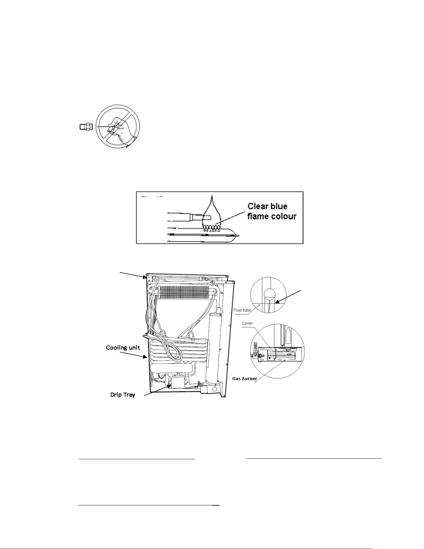
Warning - DO NOT use a pin or wire when cleaning the
burner orifice as damage can occur to the precision opening.
This can cause damage to
the refrigerator or create a fire hazard.
It will also create extremely dangerous levels of carbon
monoxide.
V
IEW OF BACK OF THE APPLIANCE
E
XPLODED VIEW OF BURNER ASSEMBLY
Visually check burner flame to ensure you have a clean burning flame, this
is represented by a blue looking flame, a yellow/orange flame represents a
dirty burner or orifice and needs to be cleaned.
Gas Hook Up
Baffle

UNIQUE UGP 3
16
WARNING – Button (D) Fig. #1, page 8, must be manually depressed to allow gas
pressure to flow to the burner orifice. Be sure to apply the leak check solution before
depressing this button. DO NOT allow any open flame, sparks, smoking, etc. in the
area of the test. DO NOT depress (D) for over 30 seconds. If leak occurs, correct
problem, recheck with leak test solution then light the burner according to the
instructions under Operation Instructions, Chapter 2

UNIQUE UGP 3
17
TROUBLESHOOTING INSTRUCTIONS &
SUGGESTED SPARE PARTS TO KEEP ON HAND
REFRIGERATOR DOES NOT COOL, CHECK LIKELY CAUSES:
1.
Burner orifice clogged. Clean. See section MAINTENANCE & SERVICE, CHAPTER 3
2.
Check to ensure refrigerator is level – (left to right and front to back).
3.
Restriction on air flow across cooling unit.
4.
Heavy frost build up on evaporator fins. Defrost.
5.
Flue baffle not inserted properly in flue tube.
6.
Improperly set thermostat. See paragraph on thermostat. In hot weather or heavy use
the setting should be closer to “Max” than usual.
7.
Burner dirty. Clean. See Section MAINTENANCE & SERVICE, CHAPTER 3,
8.
LP gas pressure low at burner. Regulator pressure must not drop below 11 inches
W.C (water column) on high fire.
9.
110V supply disconnected or heating element not functioning
10. Burner damaged. Replace.
11.
Odours and fumes
Dislocated burner
Damaged Burner
Dirty orifice
Dirty flue tube – CHAPTER 4.
Chapter
4

UNIQUE UGP 3
18
Suggested Spare Parts
The following is a list of commonly used parts which are available:
Burner orifice
Burner
Electrode
Thermocouple
Baffle
Contact your dealer or an authorized service center for parts and repairs as needed. Quote
Model & Serial # - See CSA rating/serial plate on back of appliance.
UNIQUE UGP 3
19
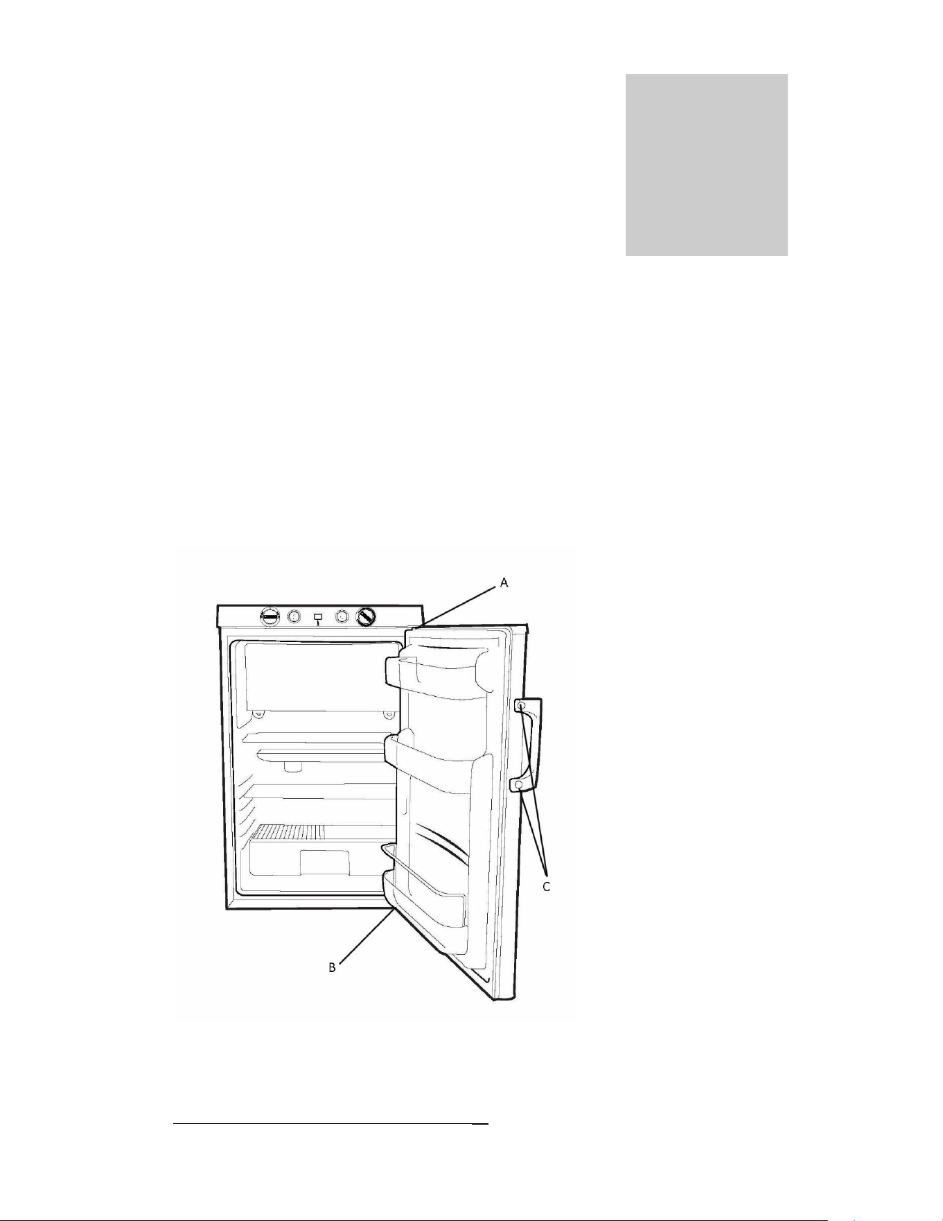
Door Removal & Reversal Instructions
This appliance has the capability of either opening the door from the left or right side. The
unit is delivered to you with the door opening from the left side, to the right. Should you
desire to reverse the opening direction, please follow instructions below.
NOTE: All parts reversible
A - Top Hinge Pin
B - Bottom Hinge
C - Door Handle
Chapter
5
UNIQUE UGP 3
20
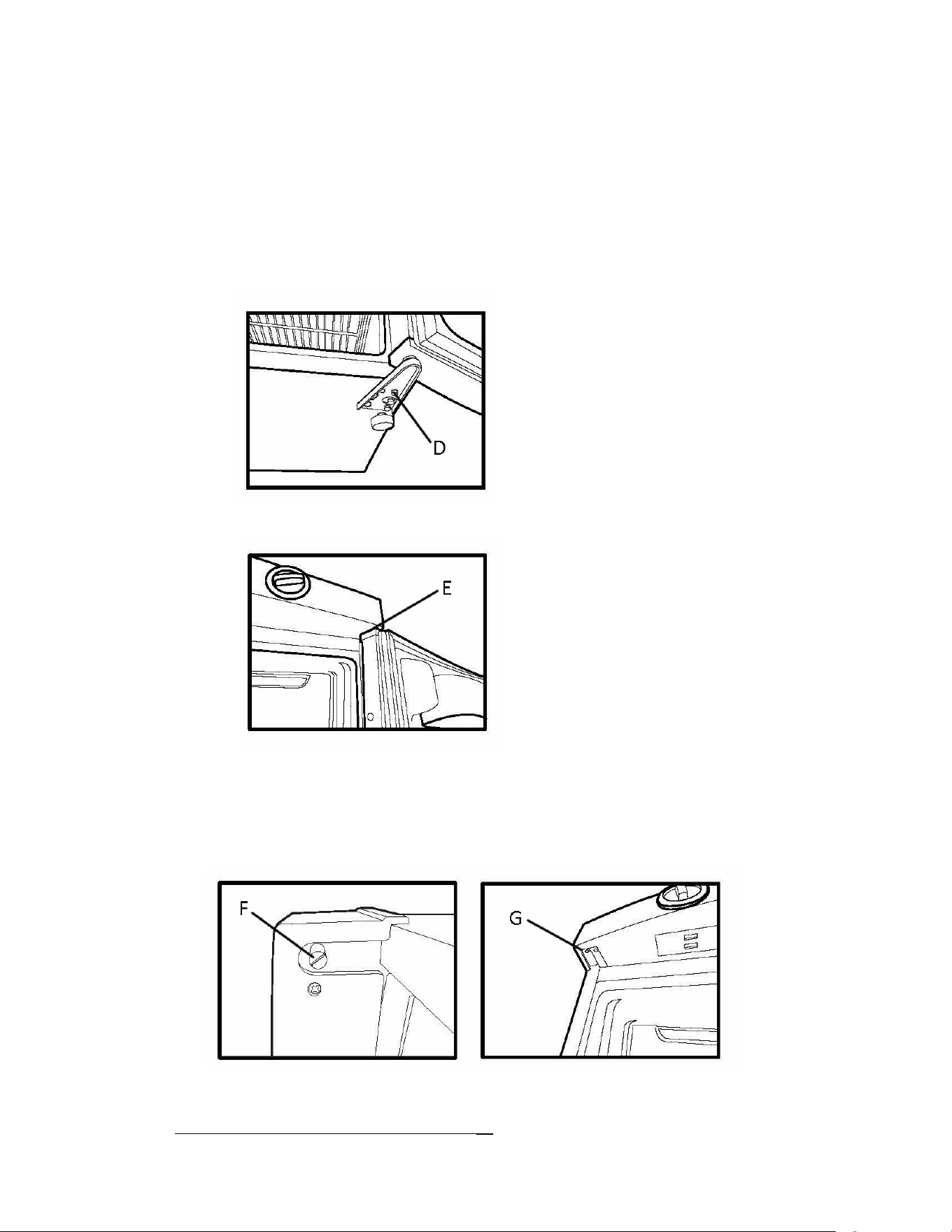
How to reverse the door:
1. Lay the fridge on one side exposing the bottom of the fridge, suggested
hinge side up.
2. Remove the lower hinge (D) by loosening and removing all the screws with
screwdriver.
3. Carefully pull away the door from top pin (E) and set aside.
4. Remove the top hinge pin (F) with a slotted screwdriver and move it to the
opposite side (G).
UNIQUE UGP 3
21
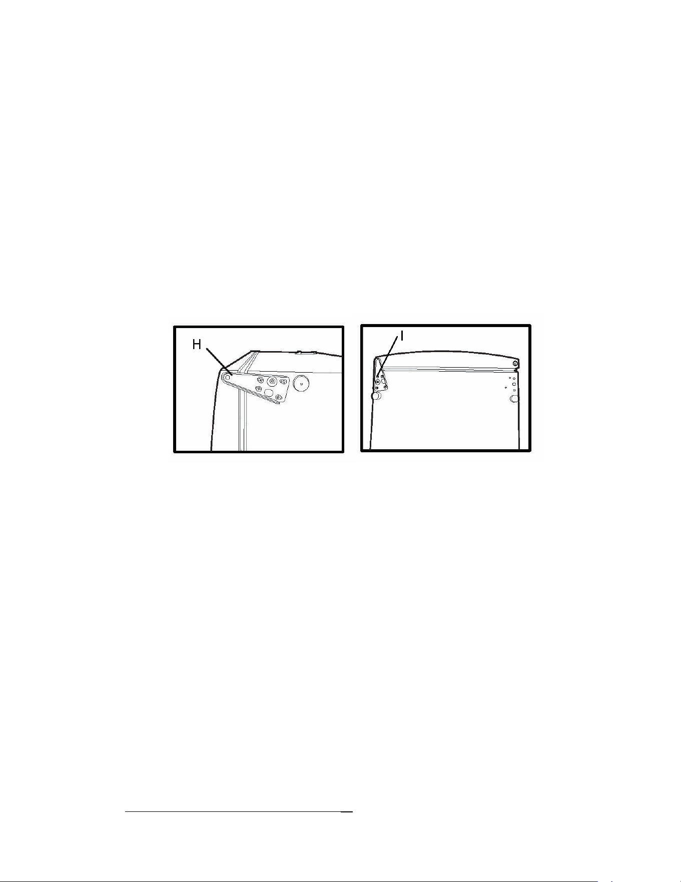
5. Turn fridge upside down and proceed to slide the top of the freezer door
onto the top hinge pin.
6. Insert the lower hinge into the bottom hole of the fridge door, also including
any round spacers that may have been present on the hinge pin when you
removed the hinge. Line up the side of the fridge door with the cabinet
before tightening hinge to bottom of cabinet. Start to fasten the lower hinge
to the bottom of the appliance. Tighten all screws once you’re sure
everything is lined up. Some screws will be self-tapped in bottom of
appliance.
7. The door handle (C) can be mounted to the other side of the door. Two
screws.
Note: As the door gasket gets pressed-in during shipment, after reversing the door the
gasket might have to be reset. If there is a gap between the cabinet and the door gasket, set
the gasket by gently pulling it out to seal the gap. If necessary, you are recommended also
to use the hair dryer to warm the gasket in hot water to get rid of the gap.
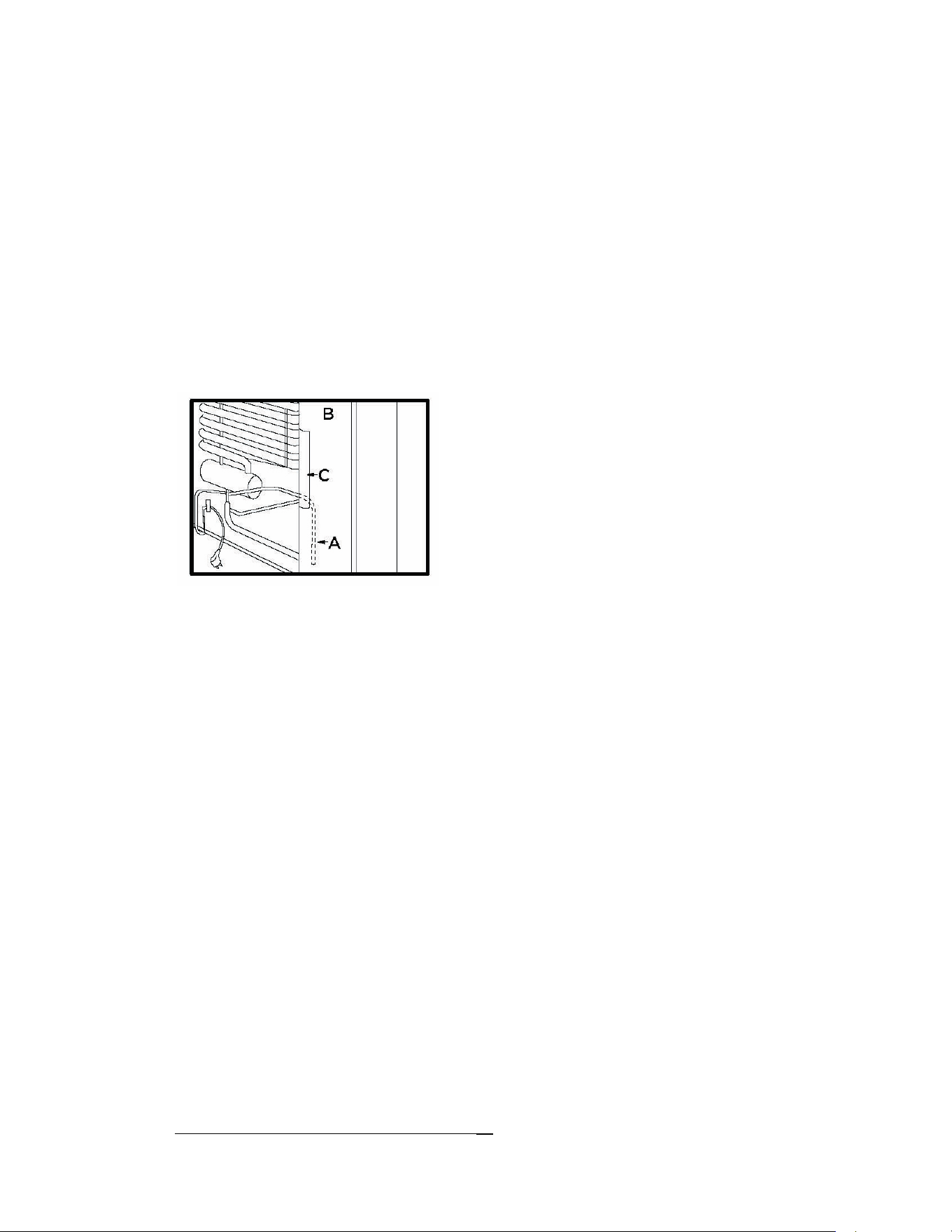
Changing the Heating Element
The heater which is fitted inside the boiler casing (B), of the refrigerator unit, can be
changed as follows:
1. Pull the power cord out of the wall socket.
2. Remove the cover (C).
UNIQUE UGP 3
22
3. Remove some insulation wool so that the heater (A) is accessible.
4. Open the terminal block cover and disconnect the heater leads.
5. Turn and lift the heater out of its pocket.
6. Fit the new heater into the pocket.
7. Connect the leads and close the terminal Block cover.
8. Carefully put the insulation wool back into position and close the cover of the boiler
casing.

UNIQUE UGP 3
23
Looking Inside
SHELF ADJUSTMENT
Refrigerator shelves are easily adjusted to suit individual needs. Before
adjusting the shelves, remove all food.
Food Storage Ideas
FRESH FOOD STORAGE
The fresh food compartment should be kept between 38° F and 40° F (3.3° C
and 4.4° C) with an optimum temperature of 38° F (3.3°C).
Avoid overcrowding the refrigerator shelves. This reduces the circulation of air
around the food and results in uneven cooling.
MEAT
Raw meat and poultry should be wrapped securely so leakage and contamination
of other foods or surfaces does not occur.
F
ROZEN FOOD STORAGE
The freezer compartment should be kept at 8.6°F (-13°C) at a 77°F (25°C) room
ambient.
A freezer operates most efficiently when it is slowly loaded to 2/3 full.
PACKAGING FOODS FOR FREEZING
To minimize dehydration and quality deterioration, use aluminium foil, freezer
wrap, freezer bags or airtight containers.
Chapter
6

UNIQUE UGP 3
24
Force as much air out of the packages as possible and seal them tightly. Trapped
air can cause food to dry out, change color, and develop an off-flavor (freezer
burn).
Wrap fresh meats and poultry with suitable freezer wrap prior to freezing.
Do not refreeze meat that has thawed.
LOADING THE FREEZER
Avoid adding too much warm food into the freezer at one time. This overloads the
freezer, slows the rate of freezing, and will raise the temperature of frozen foods.
Leave a space between the packages, so cold air can circulate freely, allowing food to
freeze as quickly as possible.
Care and Cleaning
Keep your refrigerator and freezer clean to prevent odor build-up. Wipe up any spills
immediately and clean both sections at least twice a year. Never use metallic scouring pads,
brushes, abrasive cleaners or strong alkaline solutions on any surface. Do not wash any
removable parts in a dishwasher.
NOTES:
Do not use razor blades or other sharp instruments, which can scratch the appliance
surface when removing adhesive labels. Any glue left from tape or labels can be removed
with a mixture of warm water and mild detergent, or, touch the glue residue with the
sticky side of tape you have already removed. Do not remove the certification/serial
plate.
UNIQUE UGP 3
25
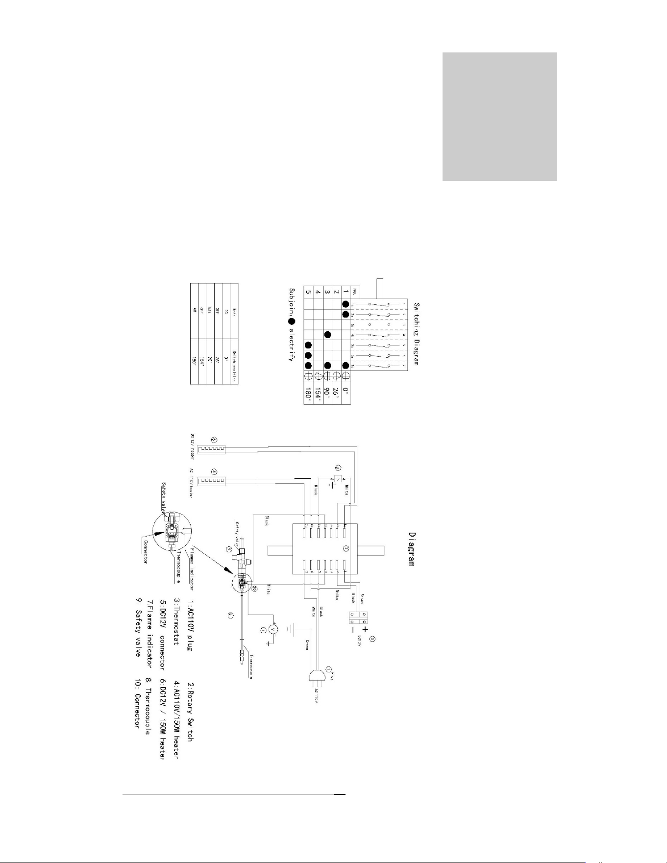
Wiring Diagram
Chapter
7
UNIQUE UGP 3
26
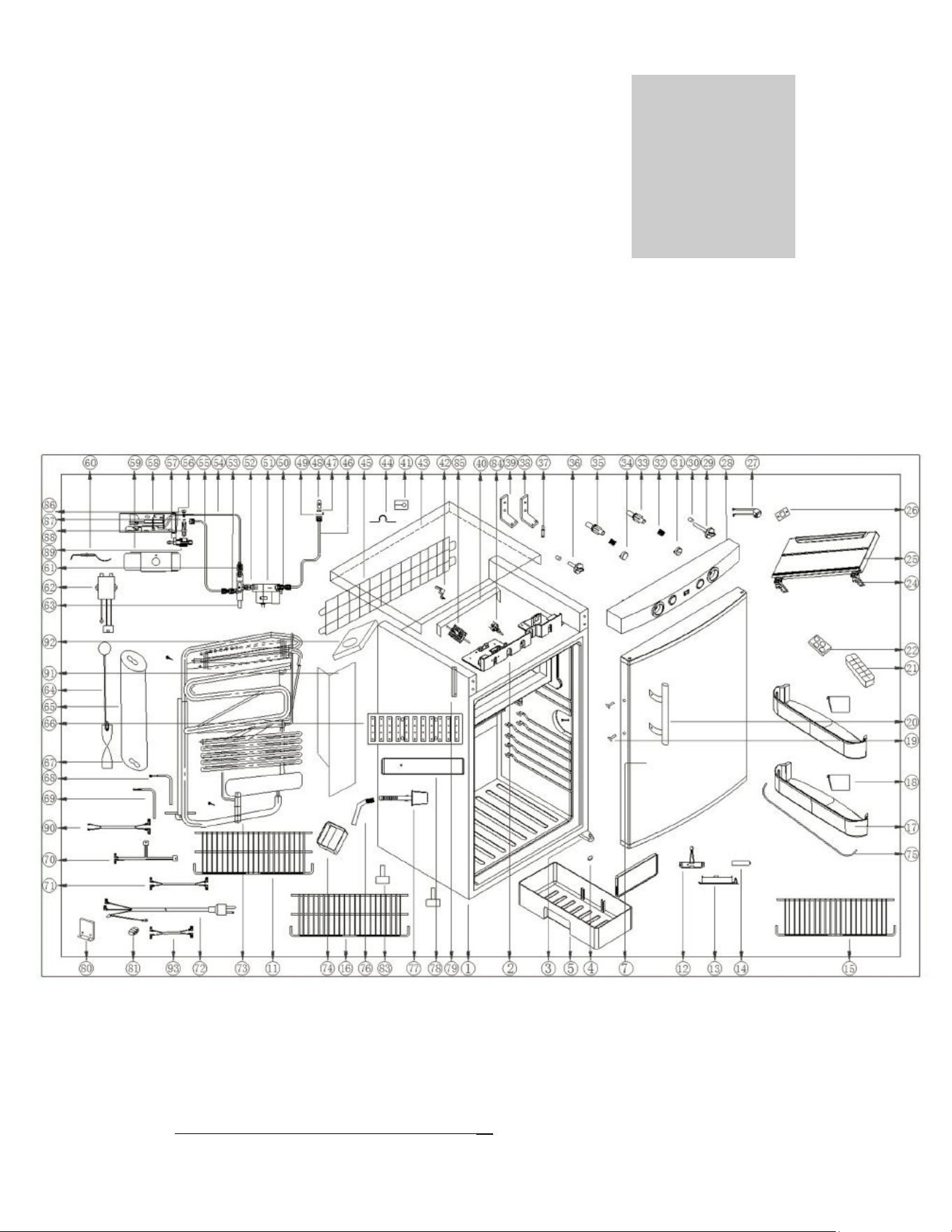
Parts Diagram and List
UNIQUEUGP3‐EXPLODEDDIAGRAM
Chapter
8
UNIQUE UGP 3
27
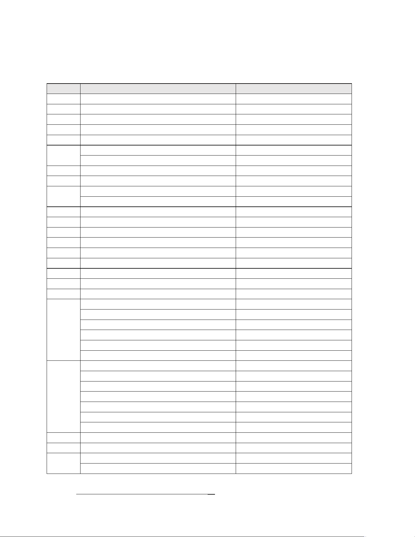
UNIQUE UGP 3 – Parts List
No. Item Code
1 Cabinet N/A
2 Frontpanelbracket UGP‐DL10001639
3 Bottomhinge UGP‐DL04001271
4 Washer UGP‐DL03001603
5 Crisper UGP‐DL08502049
7
Fridgedoor‐White UGP‐DLXCD‐100AW
Fridgedoor‐Black UGP‐DLXCD‐100AB
11 Bottomshelf UGP‐DL10001732
12 Batterybox UGP‐DL08502152
13
Batteryboxholder‐White UGP‐DL10001624
Batteryboxholder‐Black UGP‐DL10001689
14 Battery N/A
15 Topshelf UGP‐DL10001730
16 MiddleShelf UGP‐DL10001731
17 Balcony UGP‐DL08502007
18 Balconyspacer UGP‐DL08502163
19 Screw UGP‐DL00002021
20Doorhandle UGP‐DL10001723
21 IcecubeTray N/A
22 Eggtray N/A
24
Freezerdoorhingeassy. UGP‐DL08502330
Spring N/A
Tophinge N/A
Bottomhinge N/A
Axle N/A
Screws N/A
25
FreezerDoorAssy. UGP‐DL08502329
Freezerdoorshell N/A
Freezerdoorliner N/A
Freezerdoorfoamblock N/A
Freezerdoorreinforcingplate N/A
Freezerdoorgasket N/A
Screws N/A
26 Flameindicatorholder UGP‐DL08502215
27 Flameindicator UGP‐DL10001527
28
Controlpanel‐White UGP‐DL10001669
Controlpanel‐Black UGP‐DL10001754
UNIQUE UGP 3
28
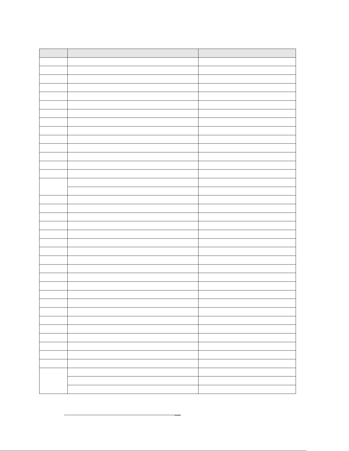
No. Item Code
29 Thermostatknob UGP‐DL 08502351
30 Ringforknob UGP‐DL08502342
31 Safetyvalvebutton UGP‐DL08502319
32 Spring UGP‐DL08502346
33 Safetyvalveconnector–GasValve UGP‐DL08502034
34 Ignitorbutton UGP‐DL08502320
35 Safetyvalveconnector‐Ignition UGP‐DL08502034
36 PowerSelectorknob UGP‐DL08502352
37 Axle UGP‐DL10001727
38 Lefttophinge UGP‐DL10001704
39 Righttophinge UGP‐DL10001705
40 Holder UGP‐DL10001706
41 Powercordholder UGP‐DL28801267
42 Gasinletclip UGP‐DL08502202
43
Topcover‐White UGP‐DL10001646
TopCover‐Black UGP‐DL10001684
44 Saddleclamp UGP‐DL00009450
45 TopBackGrill UGP‐DL10001722
46 Pipeforgasinletnipple UGP‐DL10001656
47 Nutforgasinletnipple UGP‐DL00003136
48 Inletnipple UGP‐DL10001506
49 Inletnippleholder UGP‐DL10001747
50Gasinletconnectorforthermostat UGP‐DL10001114
51 Thermostat–with“A”bypassorifice UGP‐DL10001430
52 Gasinletconnectorforsafetyvalve UGP‐DL10001658
53 Gasoutletconnectorforsafetyvalve UGP‐DL10001406
54 Thermocouple UGP‐DL08502311
55 Gaspipeforburner UGP‐DL10001655
56 Injector UGP‐DL10001712
57 NutforInjector UGP‐DL10001474
58 Burnerassembly UGP‐DL10001496
59 Burnercoverassy UGP‐DL22502506
60 Electrode UGP‐DL08502222
61 Thermocoupleconnector UGP‐DL22001180
62 Batteryignitor UGP‐DL08502310
63 Safetyvalve UGP‐DL18501005
64
BaffleAssembly UGP‐DL10001760
Baffleholder UGP‐DL10001035
Baffle UGP‐DL10001139
UNIQUE UGP 3
29
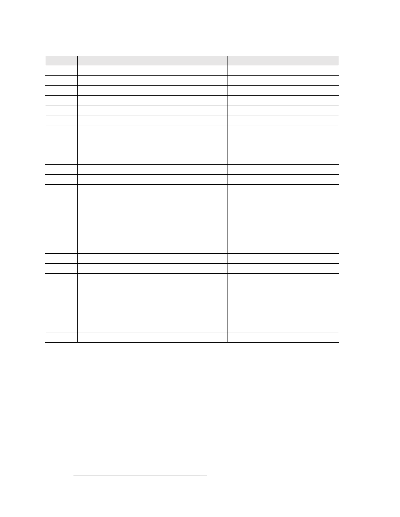
No. Item Code
65 Insulationcover UGP‐DL 10001273
67 Insulationcap UGP‐DL22501422
66 Heatsink UGP‐DL08502324
68 Heater UGP‐DL10001743
69 DC12VHeater UGP‐DL10001692
70 Connectionwire–notshown UGP‐DL10001650
71 Connectionwire UGP‐DL10001745
72 PowerCord UGP‐DL10001759
73 Coolingunit N/A
74 Drainagebox UGP‐DL08502269
75 Bottlerackwire UGP‐DL10001662
76 Drainagehose UGP‐DL00010078
77 Drainagehose UGP‐DL22501090
78 Drainagebox UGP‐DL10001005
79 Thermostatprobeholder UGP‐DL08502164
80 Terminalblockholder UGP‐DL10001746
81 Terminalblock UGP‐DL00013792
83 Foot UGP‐DL04006036
84 Pushbuttonswitch UGP‐DL08502095
85 RotarySwitch UGP‐DL10001213
86 Checkpointplug UGP‐DL22501206
87 Washer UGP‐DL00009306
88 Checkpointconnector UGP‐DL10001501
89 Checkpointbody UGP‐DL10001498
90 Connectionwire UGP‐DL10001693
91 Heatshield UGP‐DL10001749
92 Heatshieldcover UGP‐DL10001750
93 Connectingwireforthermocouple UGP‐DL08502068

UNIQUE UGP 3
30
Warranty
UNIQUE UGP-3
PROPANE REFRIGERATOR - 3 YEAR LIMITED WARRANTY
Unique Gas Products Ltd. warrants that this UNIQUE UGP 3 refrigerator is free from defects in material and
workmanship under normal usage and service under the following terms:
1. This Warranty is made only to the first purchaser (”original purchaser”) who acquires this refrigerator for
his/her own use and will be honored by Unique Gas Products Ltd. and by the Seller.
2. Any part of this refrigerator returned to the Seller or Unique Gas Products Ltd., which upon examination
is determined by them to have been defective in material or workmanship, will at their option be either
repaired or replaced under this warranty, without charge for materials/parts. (customer is responsible for
labour)
3.
The obligation to repair or replace defective parts will apply only to parts returned within one year of the
date of purchase and will constitute the Sellers sole obligation under this Warranty.
The Seller will have no obligation under this warranty with respect to conditions unrelated to the material or
workmanship of this refrigerator. Such unrelated conditions include without limitation:
a) faulty installation (or venting) and damage resulting therefrom; not installed by Seller
b) the need for normal maintenance of this refrigerator (including the cleaning of the
Burner, Venturi, Orifice, Flue tubes and assurance of proper propane gas pressure);
c)
any accidents to or misuse of any part of this refrigerator and any alteration thereof by anyone other than
the Seller or its authorized representative.
This
UNIQUE UGP 3 refrigerator must be serviced regularly as outlined in the Owner’s Manual. Unique Gas
Products Ltd. and the seller will not be liable for direct or indirect loss of foods caused by failure in operation. In
case of failure, the owner must provide proof of purchase, Model, and Serial Number to the Seller or Unique Gas
Products Ltd.
*Due to remote locations, it is the customer's responsibility to bring items to dealer for review.
2245 Wyecroft Road
Oakville, Ontario, Canada, L6L 5L7
Toll Free: 1-877-427-2266
Ph: 905-827-6154 www.UniqueOffGrid.com Fax: 905-827-2027
For questions related to the operation, safety or the purchase of your appliances, please contact your
dealer for more information. For general information, contact our customer service department:
APPLIANCE INFORMATION
(manual copy - keep with your records)
To make care and servicing of your appliance easy and efficient, please record the following information for
future reference:
Model:
Serial Number:
Purchased From:
Date Purchased:
APPLIANCE INFORMATION
CONTACT US
Toll-free
1-877-427-2266 or 1-905-827-6154
(available during regular business
hours, 8:30 am to 4:30 pm, EST.
Website
www.uniqueappliances.com
Email
info@UniqueAppliances.com
Scan the QR Code
or
Visit our website at https://uniqueappliances.com/product-registration/ to
register your product.
PRODUCT REGISTRATION

©2022 Unique Appliances Ltd., 2245 Wyecroft Road #5,
Oakville, Ontario, Canada, L6L 5L7
www.UniqueAppliances.com