Loading ...
Loading ...
Loading ...
6
Readings with up to 6 ½ digit resolution
With a resolution of up to 6 ½ digits when measuring
voltage, current and power, the R&S®NGL200 power sup-
plies are perfect for characterizing devices that have low
power consumption in standby mode and high current
in full load operation. The entire measuring range is cov-
ered without having to switch ranges. This results in faster
measurements. In many cases, an additional digital multi-
meter is no longer necessary.
Galvanically isolated, floating channels
Both channels of the R&S®NGL202 are completely iso-
lated from each other and are not connected to chassis
ground. They can be used as independent power supplies
or be cascaded. The channels can be connected in parallel
to achieve higher currents or in series to achieve higher
voltages. Connecting the two channels makes it easy to
power bipolar circuits that might need +12V/–12V, for
example.
Output stage isolated with relays
Switching off an output channel of a standard power sup-
ply usually simply switches off the output voltage – the
output stage of the supply remains connected to the out-
put terminals. The R&S®NGL200 uses relays to isolate the
power supply circuits from the connector sockets.
Two quadrants: operates as source and sink
The two-quadrant architecture of the power supplies
allows them to function both as a source and a sink and
simulate batteries or loads. The power supply automati-
cally switches from source mode to sink mode. As soon
as the externally applied voltage exceeds the set nominal
voltage, current flows into the power supply. This is indi-
cated by a negative current reading.
Constant voltage, constant current and constant resistance
modes
Configuring and regulating the output voltage (constant
voltage mode) is the standard application for power sup-
plies. However, the R&S®NGL200 power supplies can also
be used in constant current mode, with each channel
separately configurable. If the configured current level is
exceeded, current limiting ensures that only the config-
ured current can flow. The output voltage is accordingly
reduced below the configured value. This prevents dam-
age to the test circuit in the event of a fault.
When operating as an electronic load, constant resistance
mode is also available. In this mode, the power supply
behaves like an adjustable resistance over the entire load
range. This makes it possible to simulate battery discharge
with a constant load resistance, for example.
Variable internal impedance
A power supply should have an internal impedance as
low as possible to suppress loading effects on the DUT.
However, there are applications where certain battery
types need to be simulated in a controlled manner or
where it is necessary to simulate the increase in internal
impedance as the battery discharges. The R&S®NGL200
power supplies support these applications due to their
adjustable internal impedance range.
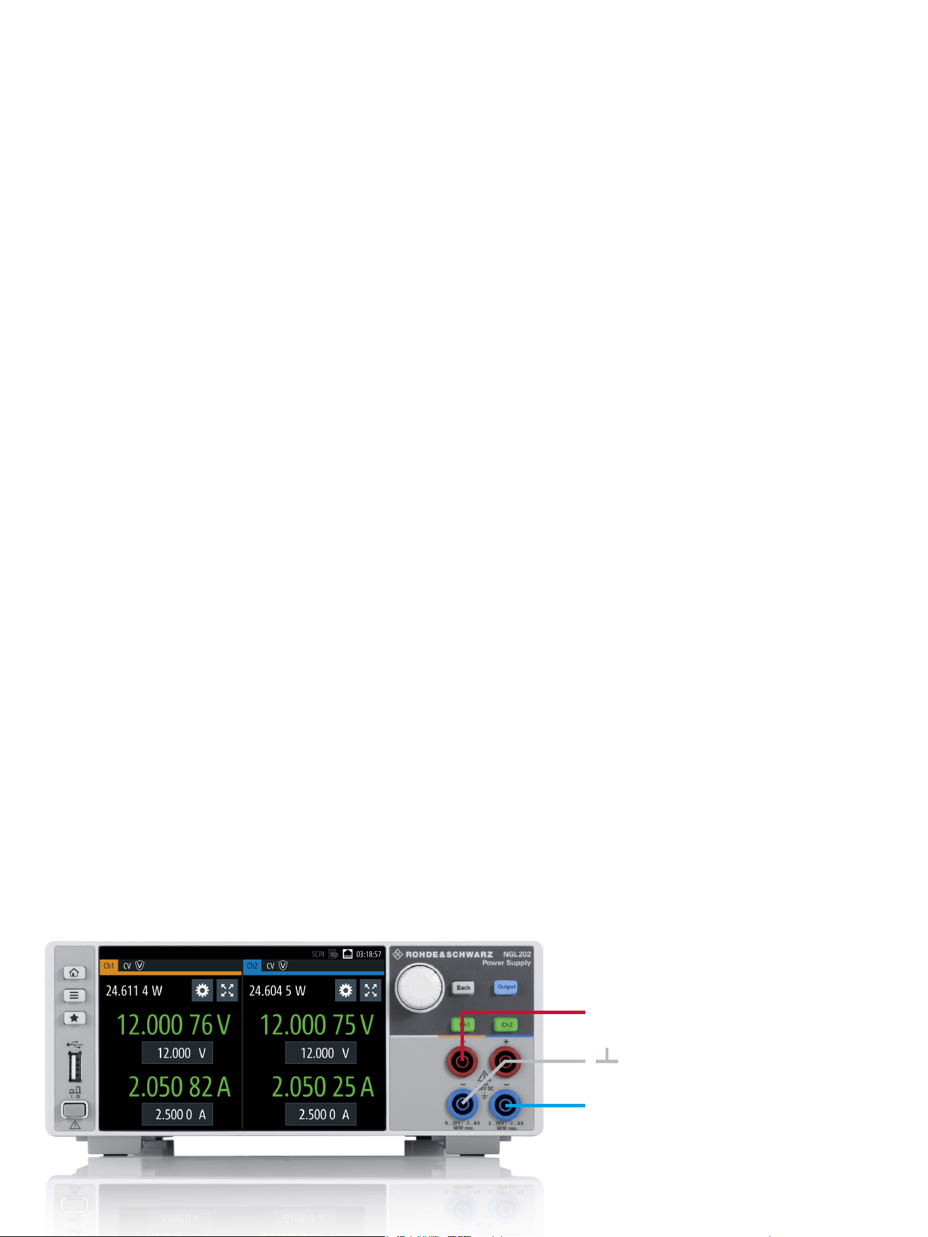
Two channels can be connected together to supply bipolar circuits with, for example, +12V/–12V.
+12 V
–12 V
Loading ...
Loading ...
Loading ...