
Loading ...
Loading ...
Loading ...
1918
ENEN
TOP COMPRESSORS UNIT:
Operate as follows:
> Unwind the electric cable and connect it directly to
the wall socket.
> Make sure the appliance is in the Stand-by condition
and that all ights are o; should it be not so press the
Unit button to switch it o.
> Firmly tighten with fingers - a tool / wrench should
not be needed to make a proper seal with the rubber
washer in the adapter. Turn on the water and ensure
all connections are not leaking prior to pushing the
unit into the opening.
3.4 Leveling
Adjust the appliance level by means of the front
levelling feet [ 1 ] and the rear adjustable wheels [ 2 ].
fig.3 Front of appliance
fig.2 Back of appliance
Operate as follows:
> If necessary, remove the bottom plinth or grille
(it is kept in position by magnets), adjust the
height of the levelling feet [ 1 ] by means of a 17
mm (11/16”) wrench.
> Then adjust the height of the rear wheels by
turning the front adjusting bolts [ 2 ] clockwise
(raise) or counter-clockwise (lower) as it may be
required.
Take care if using a power driver for this and
lower the clutch to prevent damaging the leveling
mechanism.
> Remount the bottom plinth or grille.
> If you’ve accidentally backed out the leveling
rod so that it is disengaged from the leveling
mechanism you will need to pull the appliance
forward to access the rear of the base, locate
the locking nut which will be loose under the
appliance and re-thread the rod through the
leveling plate of the mechanism and reinstall the
locking nut and re-attempt the leveling.
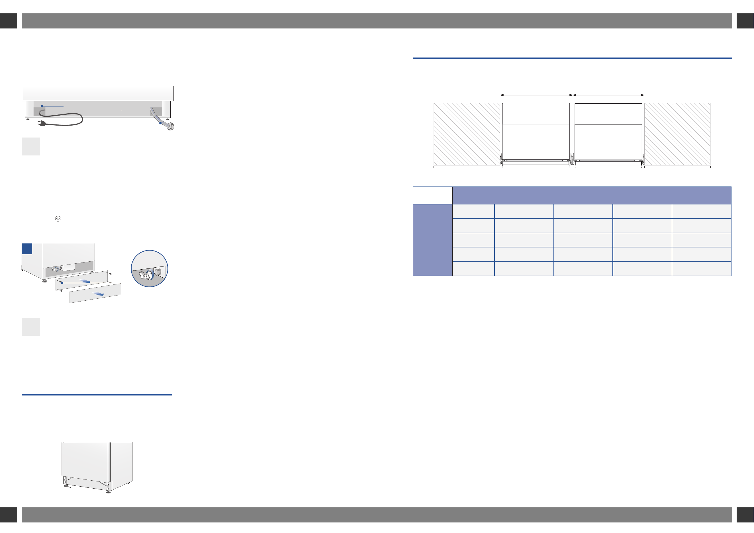
4.1 Cutout dimension for combined installation (for all models except top
compressor units fitted to European-sized cutouts)
A
B
18” model 24” model 30” model 36” model
18” model 36”(914mm) 42”(1067mm) 48”(1220mm) 54”(1372mm)
24” model 42”(1067mm) 48”(1220mm) 54”(1372mm) 60”(1520mm)
30” model 48”(1220mm) 54”(1372mm) 60”(1520mm) 66”(1676mm)
36” model 54”(1372mm) 60”(1524mm) 66”(1676mm) 72”(1829mm)
CORRECT SPACING BETWEEN APPLIANCES SHOWN LATER IN THIS MANUAL.
3. PREPARING THE INSTALLATION 4. CUTOUT DIMENSIONS
> Example: if appliance A is 24” and appliance
B is 36” the required opening width will be
24”+36”=60”
1
Electrical connection
Water connection
1
2
1
2
A
B
Loading ...
Loading ...
Loading ...