MODULAR
INSTALLATION
INSTRUCTIONS

2
w
Grills 3
IGM Cabinet to ICC90 Cabinet 4
IGM Cabinet to IFM Fridge 6
IGM Grill Cabinet to IGM Grill Cabinet 8
IGM Cabinet to ICC45 Cabinet 10
Side Burners 12
ICM-SB Cabinet to ICC45 Cabinet 13
ICM-SB Cabinet to ICC90 Cabinet 15
ICMSB Side Burner Cabinet to
ICM-SB Side Burner Cabinet 17
ICM-SB Cabinet to IFM Fridge 19
ICM-SB Side Burner Cabinet to IGM Grill 21
Sinks 23
ICM-SK Cabinet to ICC45 Cabinet 24
ICM-SK Cabinet to ICC90 Cabinet 26
ICM-SK Cabinet to ICM-SB Cabinet 28
ICM-SK Cabinet to ICM-SK Cabinet 30
ICM-SK Cabinet to IFM Fridge 32
ICM-SK Sink Cabinet to IGM Grill 34
Storage 36
ICM Cabinet to ICC45 Cabinet 37
ICM Cabinet to ICC90 Cabinet 39
ICM Cabinet to ICM Cabinet 41
ICM Cabinet to ICM-SB Cabinet 43
ICM Cabinet to ICM-SK Cabinet 45
ICM Cabinet to IFM Fridge 47
ICM Cabinet to IGM Grill 49
End Panels 51
End Panel to 90 Degree Corner
Bracket Package 52
End Panel to Storage Cabinet 54
End Panel to Side Burner Bracket
Package 56
End Panel to Sink Bracket Package 58
End Panel to Fridge Module Package 60
End Panel to Grill Bracket Package 61
End Panel to Storage Cabinet
with Cutting Board Option 63
Table of Contents

3
GRILLS
4
REVISION HISTORY
REV
DESCRIPTION
DATE
APPROVED
TITLE
SIZE
Customer
DWG NO
REV
SCALE SHEET
Finish
N/A
B
IGM Cabinet to ICC90 Cabinet
00
Engineering Release
01/01/2021
Todd Stone
37 Adams Blvd., Brantford, Ontario, N3S 7V8
P: (519) 751-1800 www.crownverity.com
1:8
1 of 2
00
IB-IGM-ICC90
Crown Verity
K Factor
Weight (Kg)
Gauge
N/A
N/A
N/A
DRAWN BY:
Todd Stone
Material
SS 304
01/01/2021
Dimensions are in inches
Linear Tolerance: +/- .015
Bend Tolerance: +/- .020
Angular Tolerance: +/- 0.5
Radial Tolerance: +/-.005
Copyright 2021 Crown Verity Inc. All rights reserved. Unauthorized duplication is a violation of applicable laws.
B
Item No. Part Number Qty Description
1 ZCV-EMC-CB-1000 4 Cabinet Connector Bracket Weld Asy
2 Screw : Hex - 0.25 x 0.5 22 Screw : Hex - 0.25 x 0.5
3 Washer : Internal Teeth - 0.25 x 0.02 23 Washer : Internal Teeth - 0.25 x 0.0255
4 Washer : Plain - 0.25 x 0.063 19 Washer : Plain - 0.25 x 0.063
5 Washer : Plain - 0.25 x 0.1 5 Washer : Plain - 0.25 x 0.1
6 Screw : Round - 0.25 x 2.5 1 Screw : Round - 0.25 x 2.5
7 Nut : Standard - 0.25 x 0.2188 1 Nut : Standard - 0.25 x 0.2188
8 ZCV-EMC-CP90-1 1 Connectro Brkt for 90 Deg Corner Cab ...
C
A
Detail B
SCALE 1 : 1.88
Detail C
SCALE 1 : 1.88
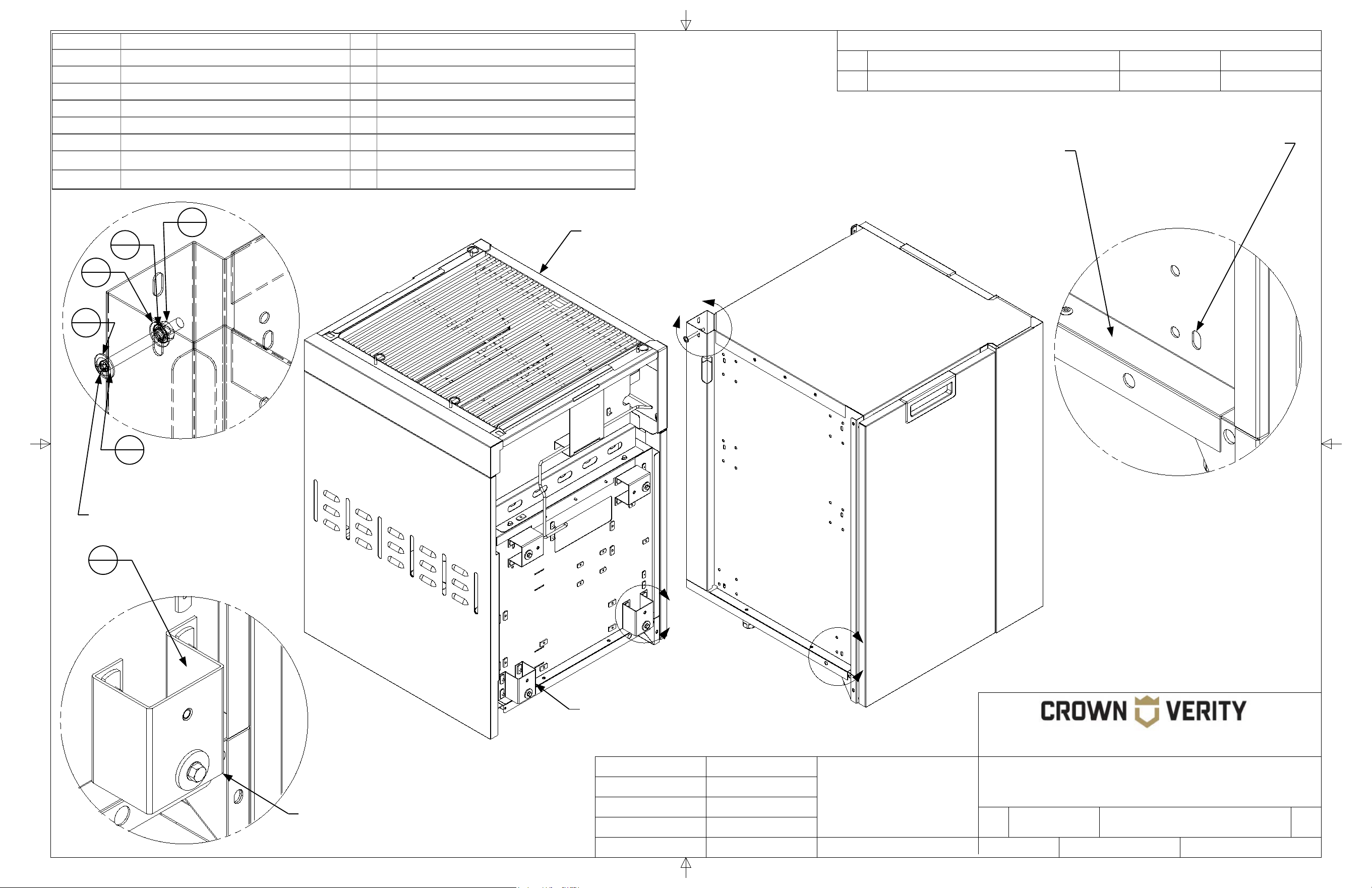
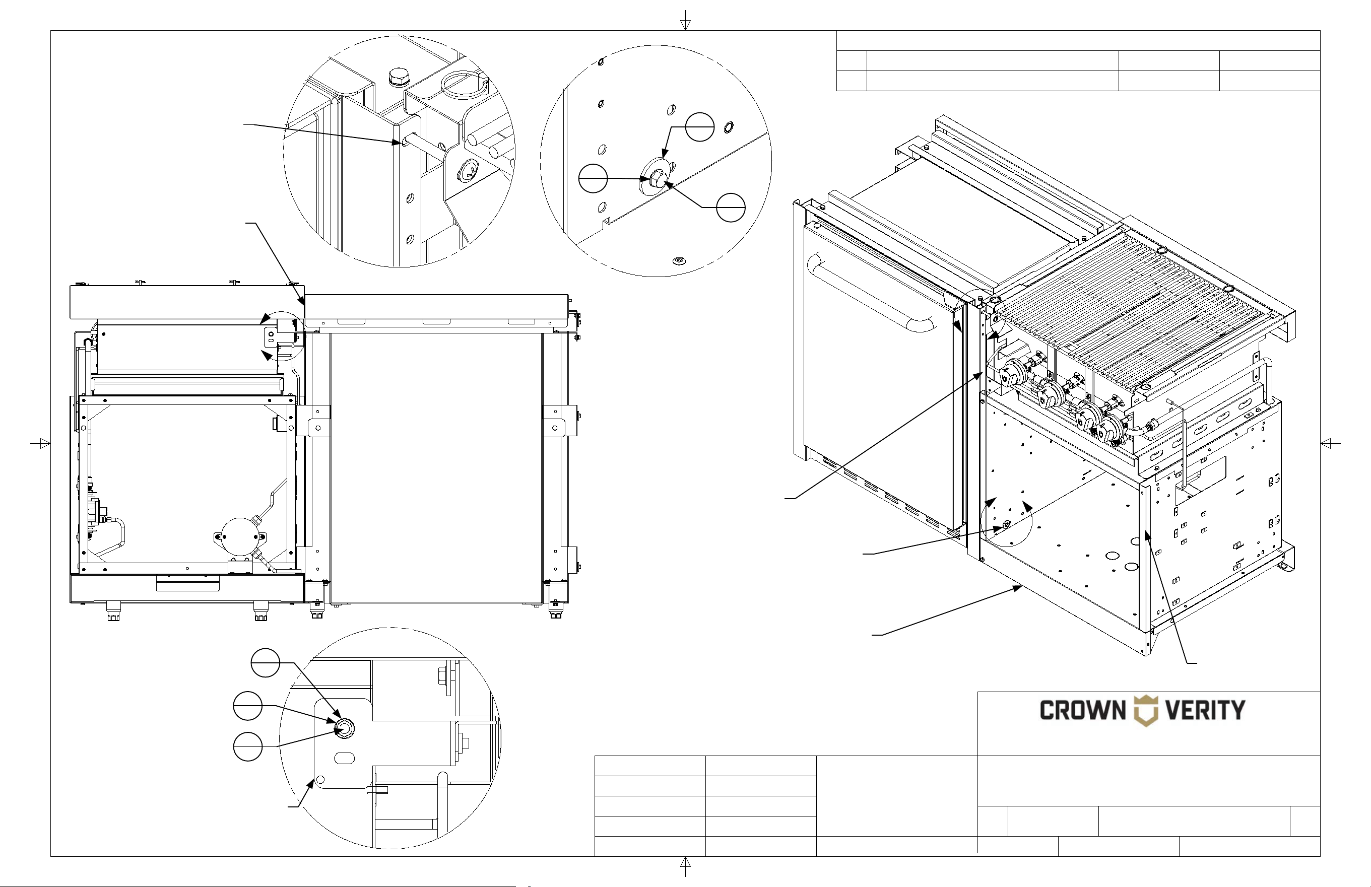
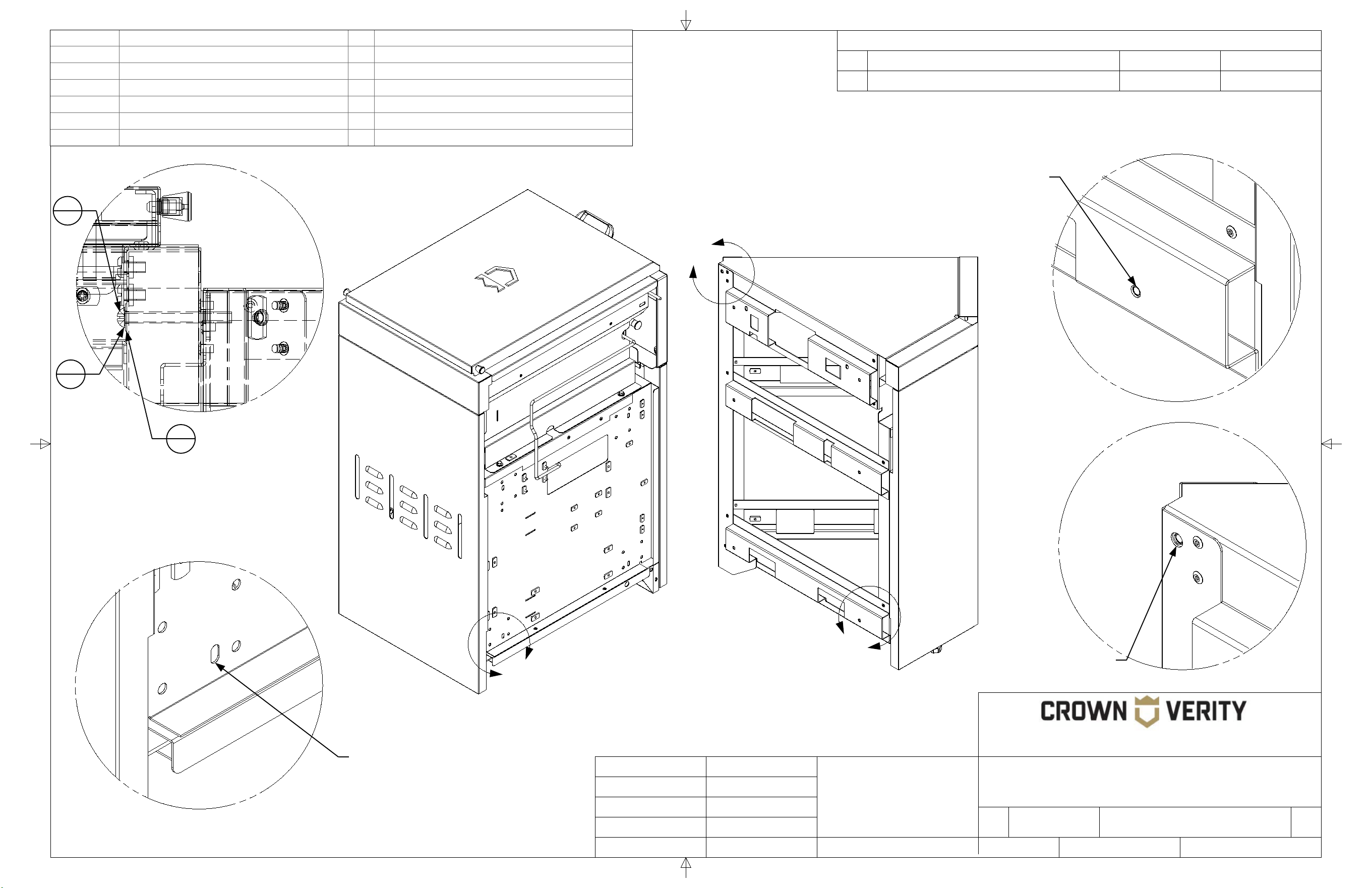
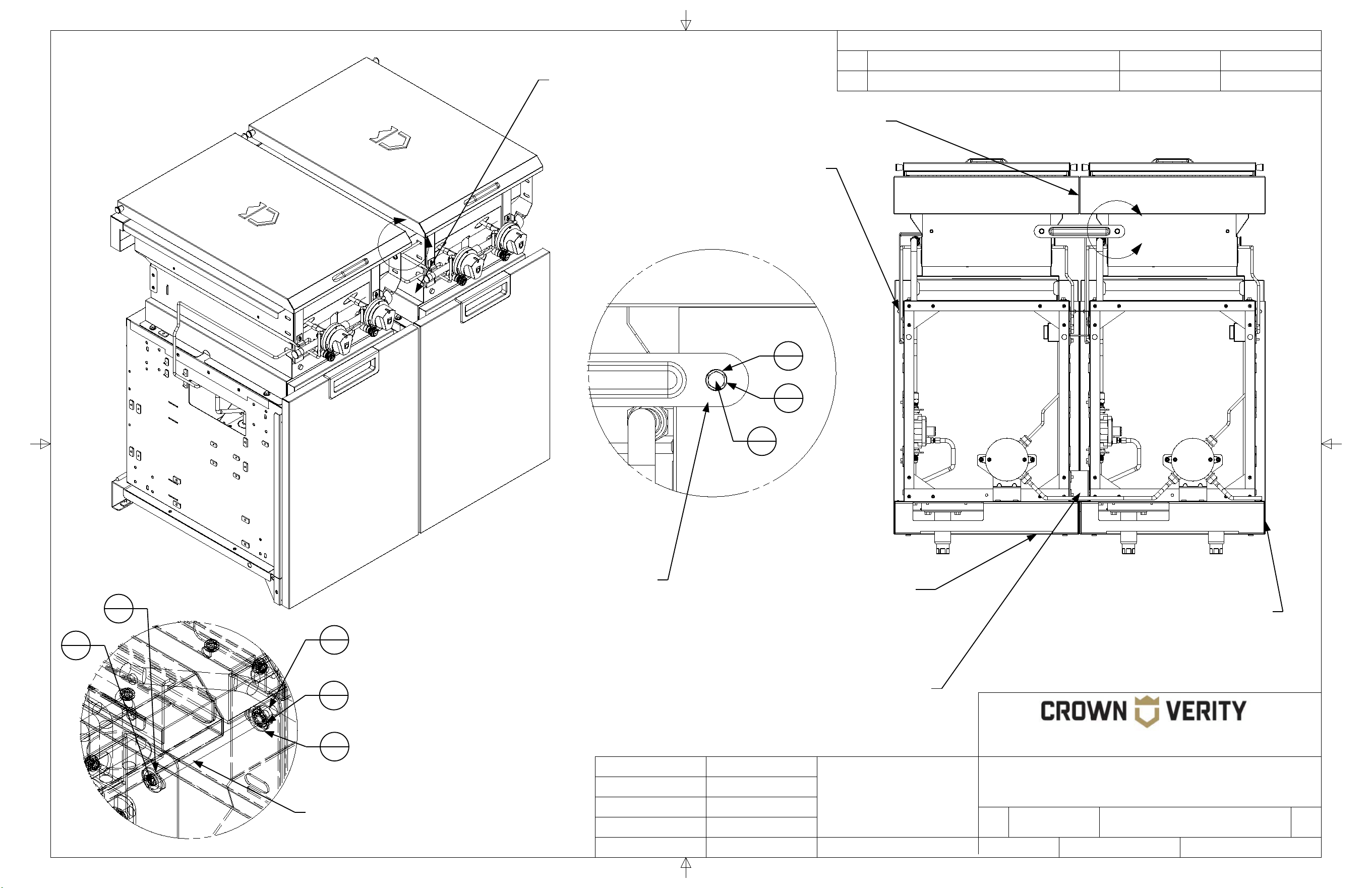
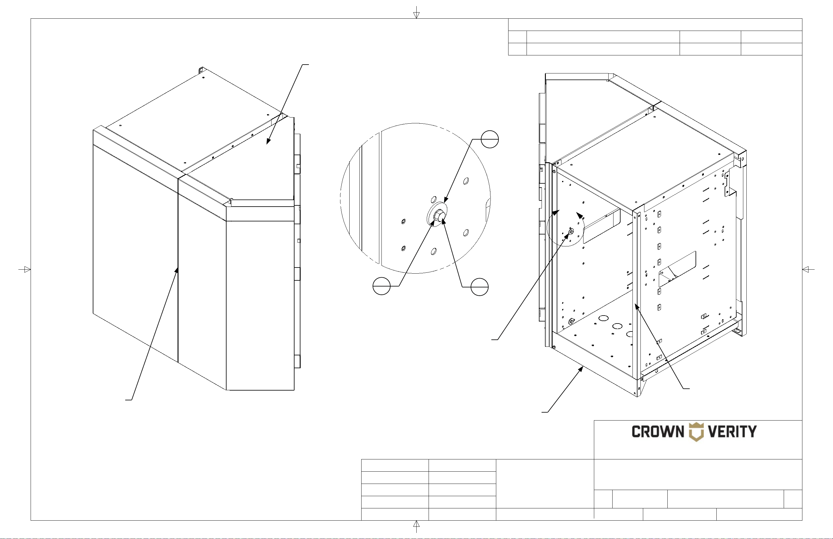
The mounting bracket of the adjacent
cabinet rest on this ledge. This
provides support for the cabinet and
eliminates the need for additional
levelling legs at the attachment point.
Note that this bracket is installed
in the opposite direction of the
bracket in Detail "B"
The brackets of the adjacent
cabinet align with these slotted
mounting holes 4 places.
1
4
Note the orientation of the
bracket when installing.
Detail A
SCALE 1 : 1.88
Mounting hardware aligns with
the corresponding slotted hole
on the adjacent cabinet. The
grill face will need to be
removed to make the
connection.
6
1
4
19
4
19
3
23
7
1
Dome has been removed
from the grill for clarity

5
REVISION HISTORY
REV
DESCRIPTION
DATE
APPROVED
TITLE
SIZE
Customer
DWG NO
REV
SCALE SHEET
Finish
N/A
B
IGM Cabinet to ICC90 Cabinet
00
Engineering Release
01/01/2021
Todd Stone
37 Adams Blvd., Brantford, Ontario, N3S 7V8
P: (519) 751-1800 www.crownverity.com
1:9
2 of 2
00
IB-IGM-ICC90
Crown Verity
K Factor
Weight (Kg)
Gauge
N/A
N/A
N/A
DRAWN BY:
Todd Stone
Material
SS 304
01/01/2021
Dimensions are in inches
Linear Tolerance: +/- .015
Bend Tolerance: +/- .020
Angular Tolerance: +/- 0.5
Radial Tolerance: +/-.005
Copyright 2021 Crown Verity Inc. All rights reserved. Unauthorized duplication is a violation of applicable laws.
D
E
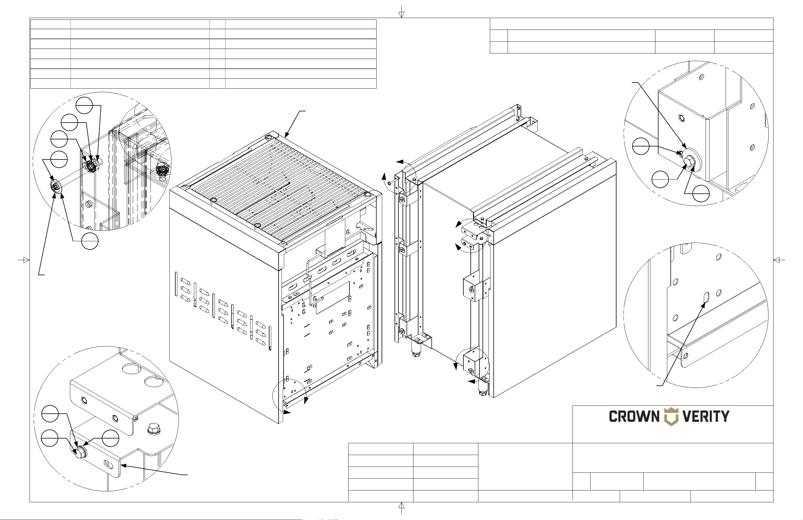
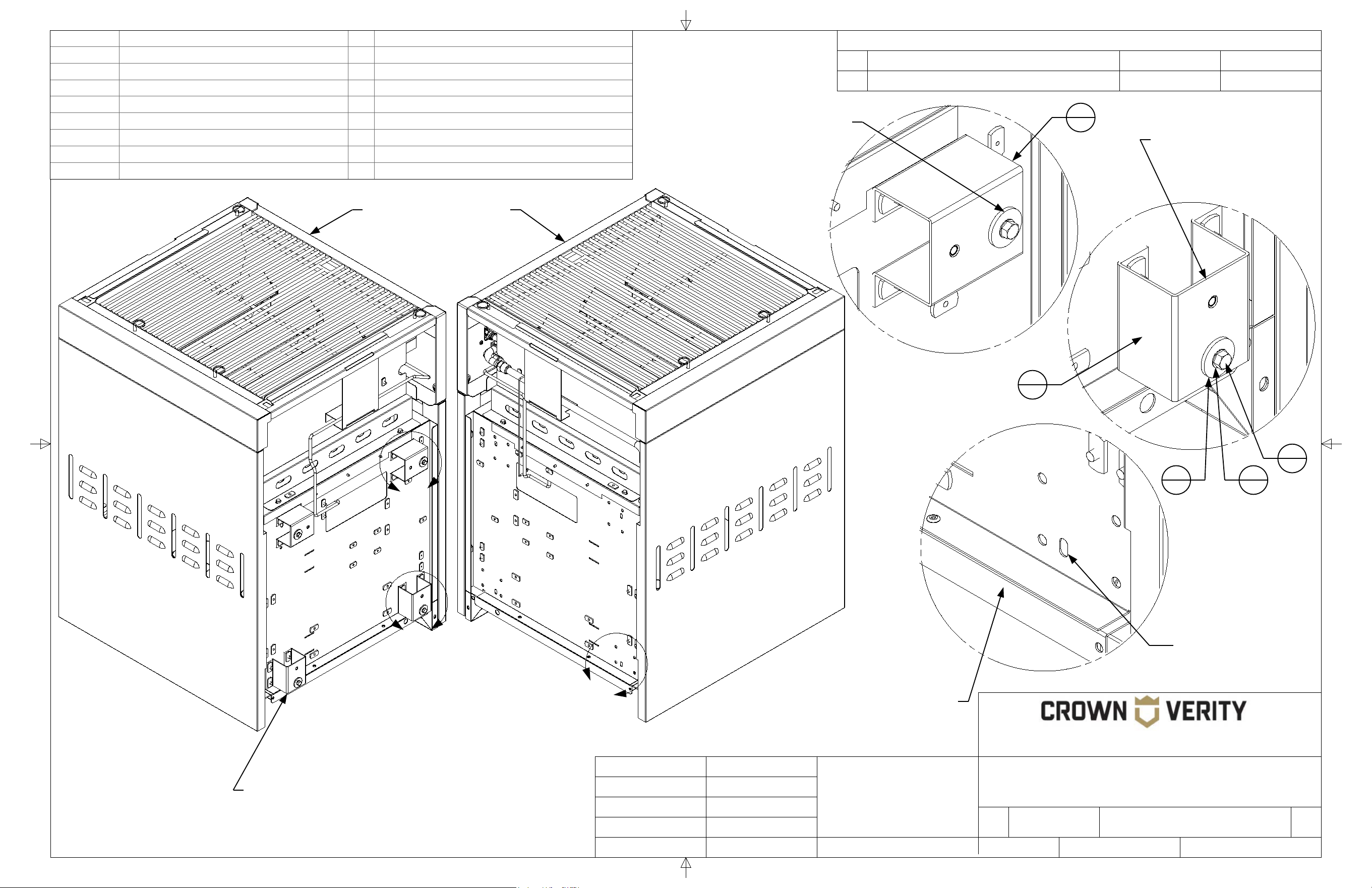
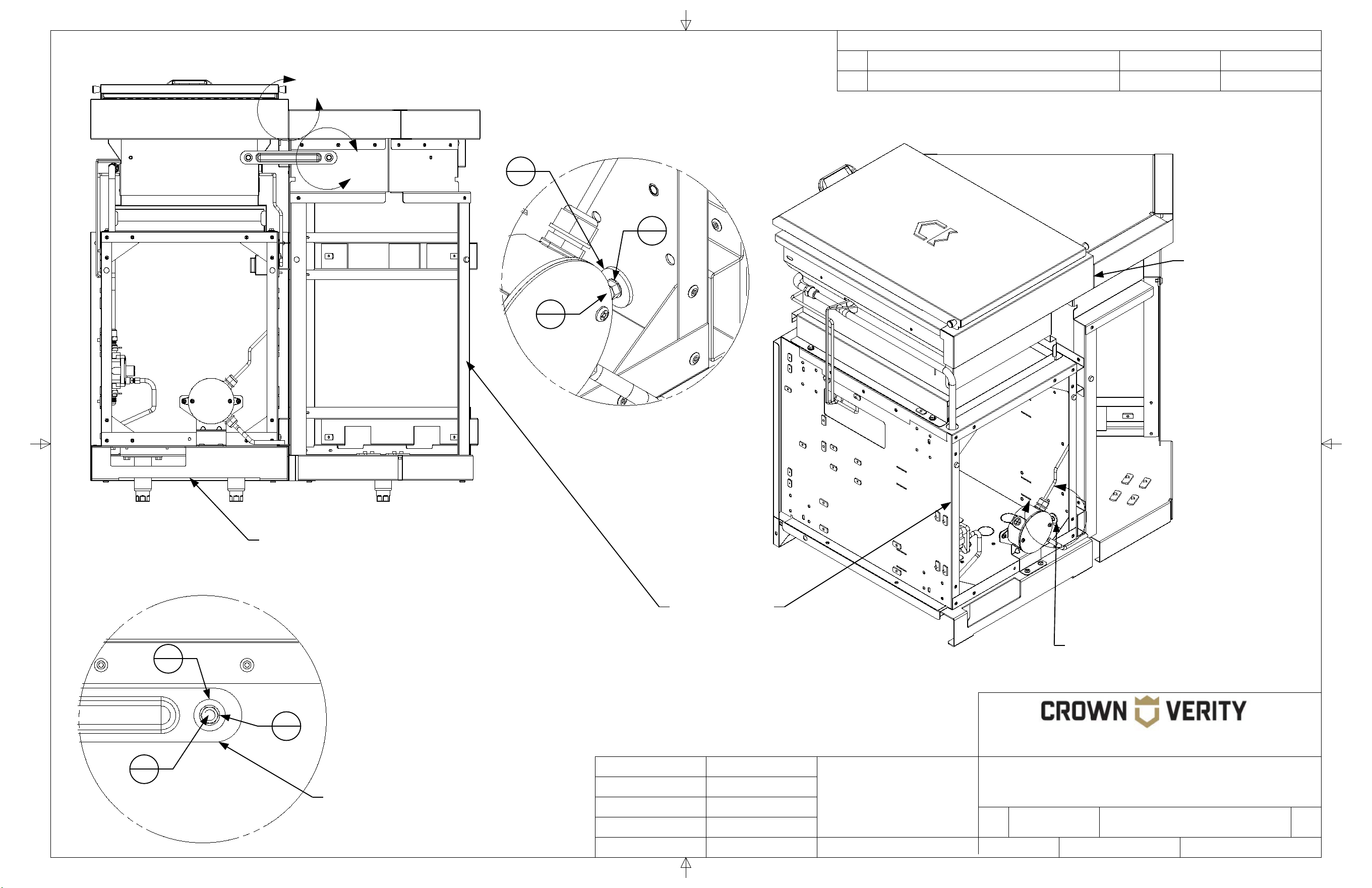
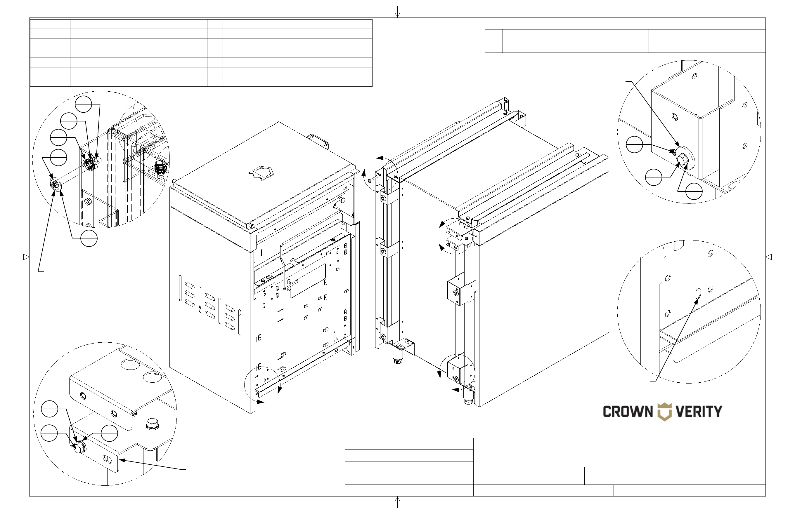
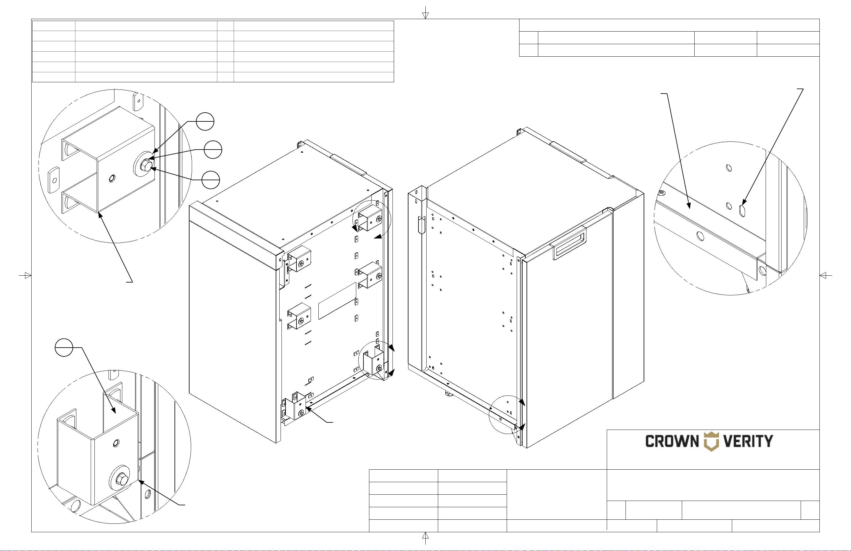
Connection to attachment
bracket using hardware
provided. 4 places. Do not
tighten until cabinets are levelled
and aligned at the back.
Align the back of
the cabinet flush to
the front face of the
door (not shown).
Door removed
for clarity
In the assembly shown the base
cabinet (initial starting cabinet) would
be put in place and levelled on all four
legs prior to attaching the next cabinet.
The attaching cabinet, would be populated with the
attachment brackets. The bottom attachment
bracket would rest on the edge of the base cabinet
for support while the hardware was installed. The
hardware would not be tightened until the attaching
cabinet is levelled and flush with the base cabinet.
The brackets are installed to the
cabinet at 4 mounting points
using the hardware provided.
2
30
3
30
4
24
Detail D
SCALE 1 : 1.88
ZCV-EMC-CP90-1
bracket attaches to
the corner cabinet at
this hole location.
Detail E
SCALE 1 : 1.88
8
1
2
22
3
23
4
19
The connector bracket is attached to the grill at this
location. There is a corresponding mounting hole on the
corner cabinet with the same mounting hardware used.
Install the bracket but do not tighten the hardware until the
cabinets have been aligned and levelled.
6
REVISION HISTORY
REV
DESCRIPTION
DATE
APPROVED
TITLE
SIZE
Customer
DWG NO
REV
SCALE SHEET
Finish
N/A
B
IGM Cabinet to IFM Fridge
00
Engineering Release
01/01/2021
Todd Stone
37 Adams Blvd., Brantford, Ontario, N3S 7V8
P: (519) 751-1800 www.crownverity.com
1:8
1 of 2
00
IB-IGM-IFM24
Crown Verity
K Factor
Weight (Kg)
Gauge
N/A
N/A
N/A
DRAWN BY:
Todd Stone
Material
SS 304
01/01/2021
Dimensions are in inches
Linear Tolerance: +/- .015
Bend Tolerance: +/- .020
Angular Tolerance: +/- 0.5
Radial Tolerance: +/-.005
Copyright 2021 Crown Verity Inc. All rights reserved. Unauthorized duplication is a violation of applicable laws.
B
Item No. Part Number Qty Description
1 Washer : Internal Teeth - 0.25 x 0.025 19 Washer : Internal Teeth - 0.25 x 0.0255
2 Screw : Hex - 0.25 x 0.5 18 Screw : Hex - 0.25 x 0.5
3 Washer : Plain - 0.25 x 0.1 10 Washer : Plain - 0.25 x 0.1
4 Washer : Plain - 0.25 x 0.063 10 Washer : Plain - 0.25 x 0.063
5 Nut : Standard - 0.25 x 0.2188 1 Nut : Standard - 0.25 x 0.2188
6 Screw : Round - 0.25 x 2.5 1 Screw : Round - 0.25 x 2.5
A
C
D
Detail B
SCALE 1 : 1.88
Detail A
SCALE 1 : 1.88
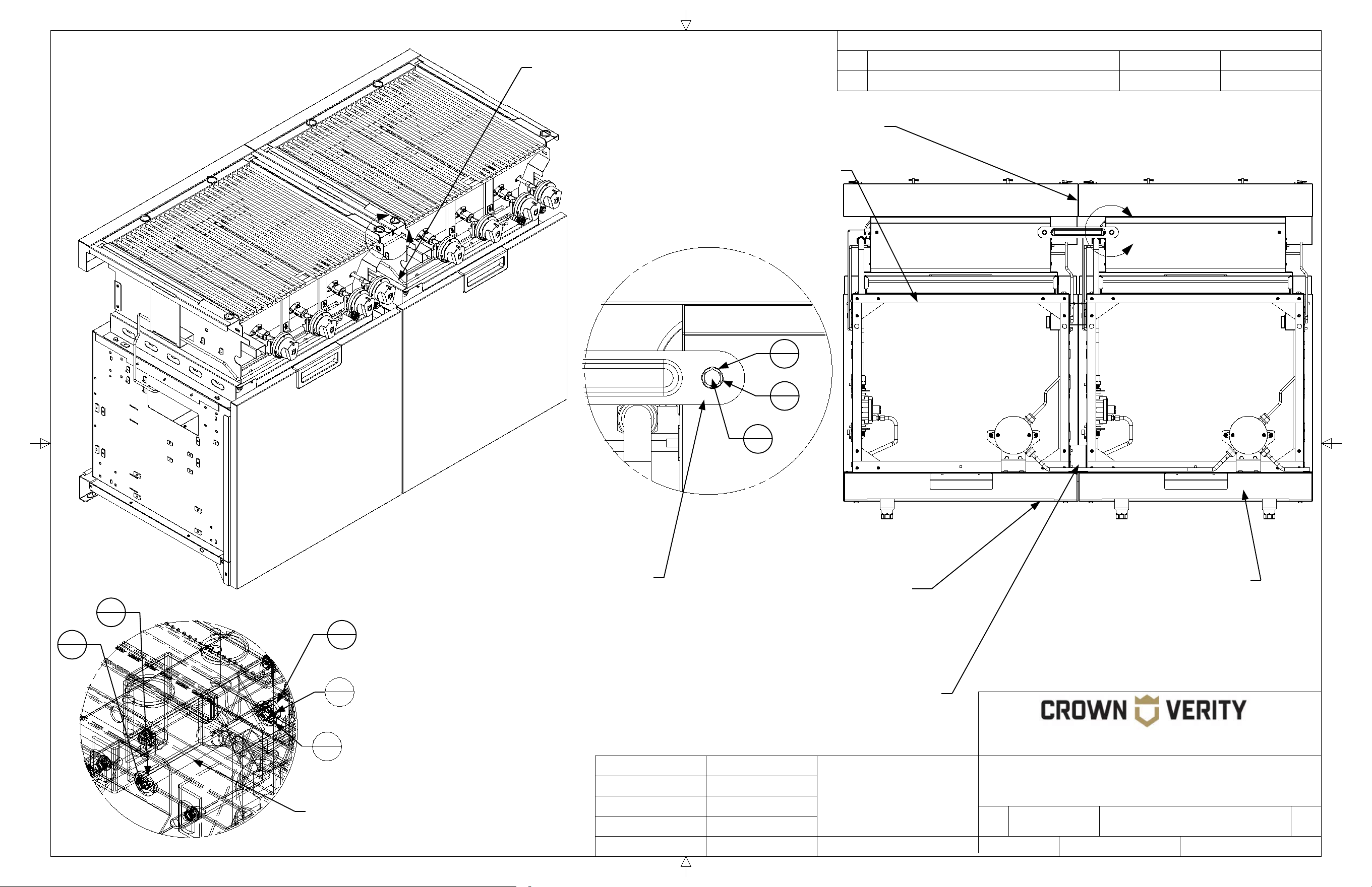
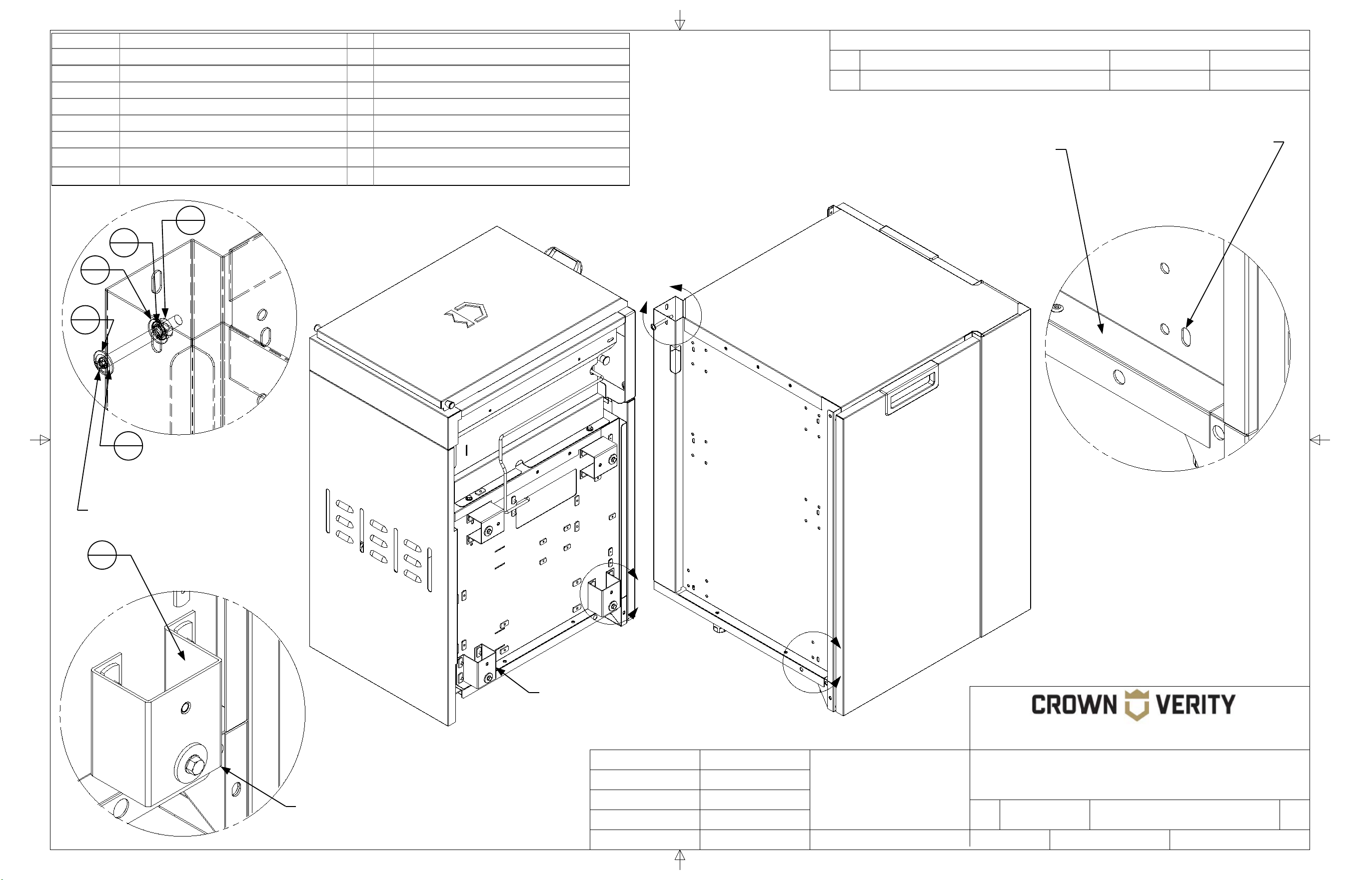
The brackets of the fridge
align with these slotted
mounting holes 4 places.
The fridge attaches to the adjacent
cabinet at these threaded insert
locations 4 places.
Detail C
SCALE 1 : 1.88
Mounting hardware for
upper rear bracket
2
18
1
19
3
10
4
10
1
19
2
18
Detail D
SCALE 1 : 1.88
Mounting hardware aligns
with corresponding slotted
hole on the adjacent
cabinet.
6
1
4
10
1
19
4
10
5
1
Dome has been removed
from the grill for clarity
7
REVISION HISTORY
REV
DESCRIPTION
DATE
APPROVED
TITLE
SIZE
Customer
DWG NO
REV
SCALE SHEET
Finish
N/A
B
IGM Cabinet to IFM Fridge
00
Engineering Release
01/01/2021
Todd Stone
37 Adams Blvd., Brantford, Ontario, N3S 7V8
P: (519) 751-1800 www.crownverity.com
1:9
2 of 2
00
IB-IGM-IFM24
Crown Verity
K Factor
Weight (Kg)
Gauge
N/A
N/A
N/A
DRAWN BY:
Todd Stone
Material
SS 304
01/01/2021
Dimensions are in inches
Linear Tolerance: +/- .015
Bend Tolerance: +/- .020
Angular Tolerance: +/- 0.5
Radial Tolerance: +/-.005
Copyright 2021 Crown Verity Inc. All rights reserved. Unauthorized duplication is a violation of applicable laws.
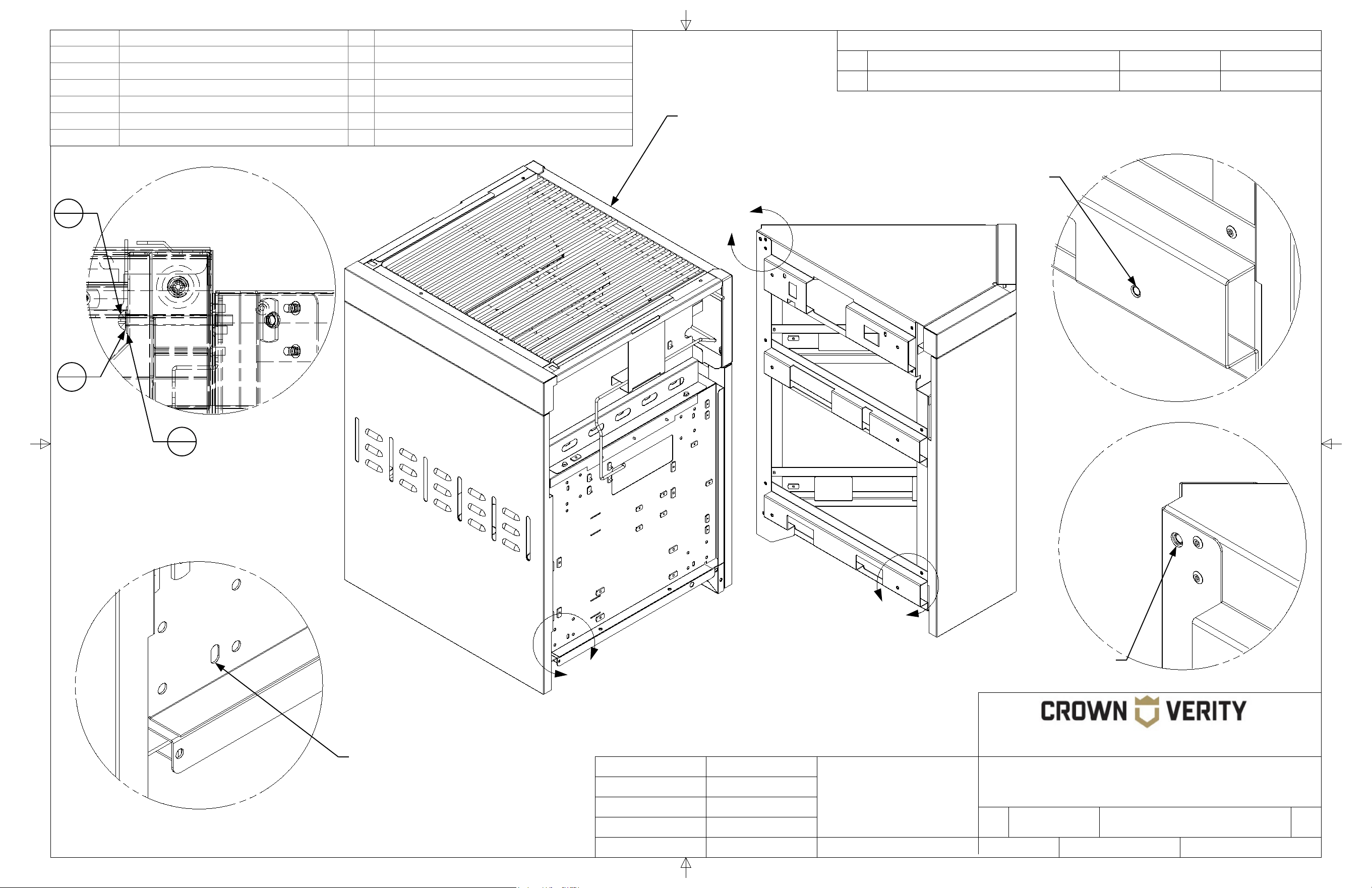
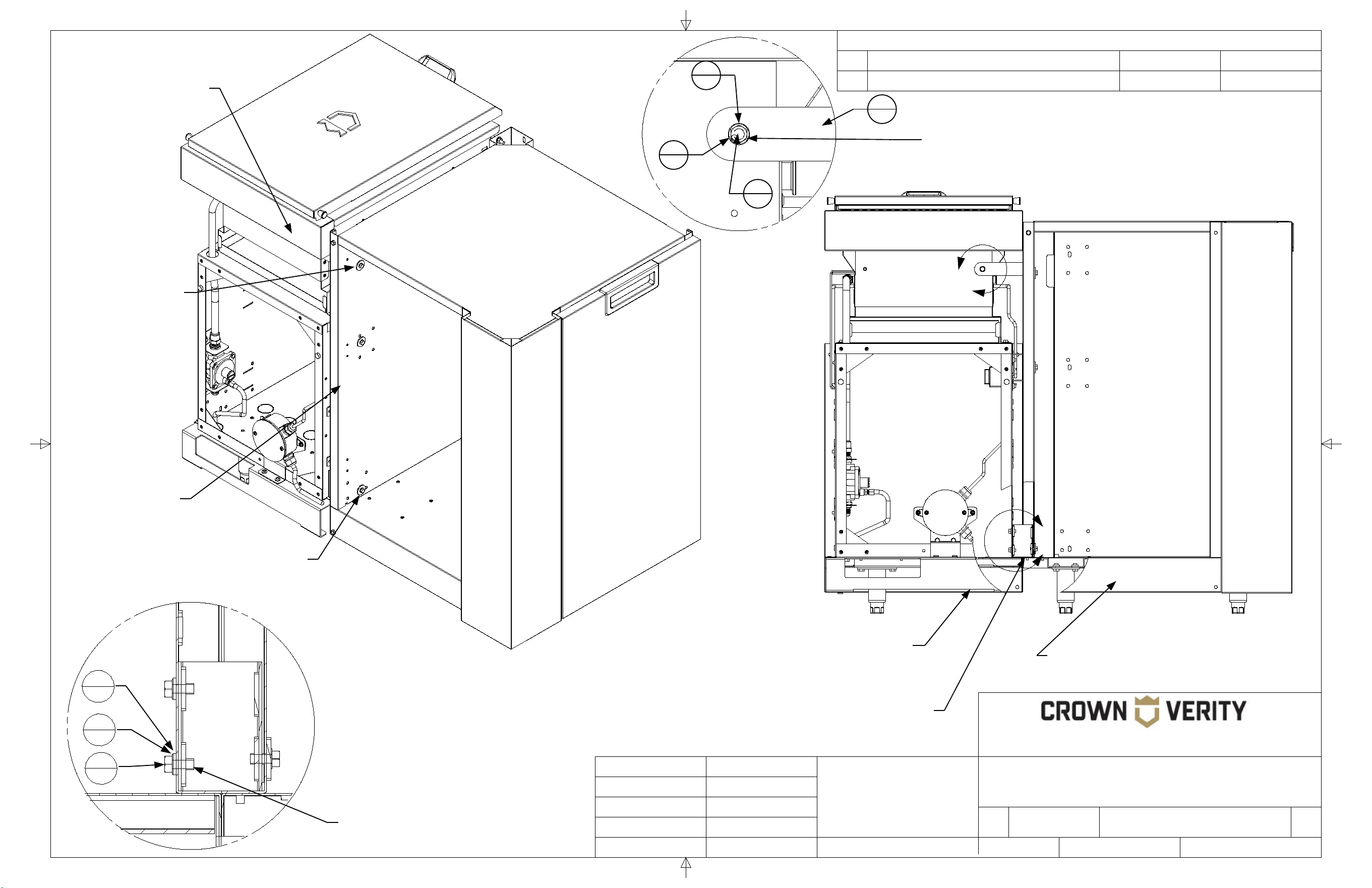
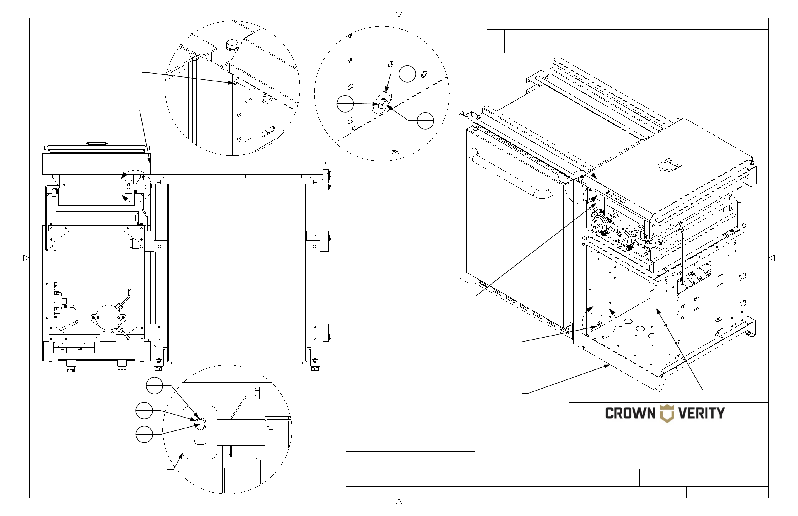
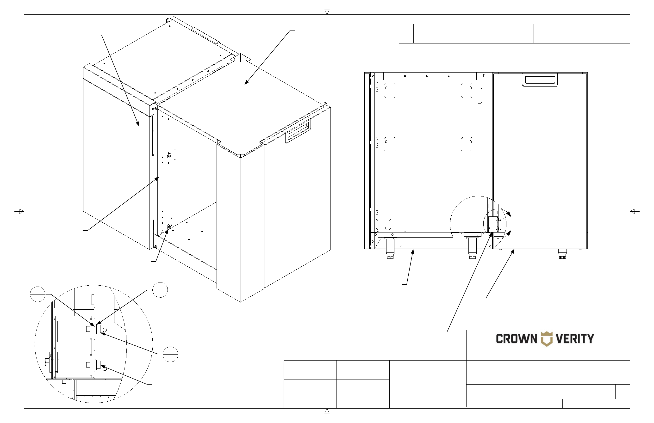
Connection to the adjacent cabinet
using hardware provided. 4 places.
Do not tighten until cabinets are
levelled and aligned at the back.
Align the back of
the cabinets flush
along this seam.
Door removed
for clarity
Cabinets connecting to a fridge
require all four legs to be installed.
The fridge does not provide
support for the adjacent cabinet.
E
F
Detail E
SCALE 1 : 2
Attach the fridge to the
upper corner of the
adjacent cabinet using
the hardware provided.
Grill face has been removed
for clarity
3
10
1
19
2
18
Detail F
SCALE 1 : 2
G
Detail G
SCALE 1 : 2
Mounting bracket ZCV-EMC-RF-8
used to connect the upper rear fridge
bracket to the upper rear of the grill.
4
10
1
19
2
18
8
REVISION HISTORY
REV
DESCRIPTION
DATE
APPROVED
TITLE
SIZE
Customer
DWG NO
REV
SCALE SHEET
Finish
N/A
B
IGM Grill Cabinet to IGM Grill Cabinet
00
Engineering Release
01/01/2021
Todd Stone
37 Adams Blvd., Brantford, Ontario, N3S 7V8
P: (519) 751-1800 www.crownverity.com
1:7.5
1 of 2
00
IB-IGM-IGM
Crown Verity
K Factor
Weight (Kg)
Gauge
N/A
N/A
N/A
DRAWN BY:
Todd Stone
Material
SS 304
01/01/2021
Dimensions are in inches
Linear Tolerance: +/- .015
Bend Tolerance: +/- .020
Angular Tolerance: +/- 0.5
Radial Tolerance: +/-.005
Copyright 2021 Crown Verity Inc. All rights reserved. Unauthorized duplication is a violation of applicable laws.
A
C
Item No. Part Number Qty Description
1 ZCV-EMC-CB-1000 4 Cabinet Connector Bracket Weld Asy
2 Screw : Hex - 0.25 x 0.5 22 Screw : Hex - 0.25 x 0.5
3 Washer : Internal Teeth - 0.25 x 0.025 23 Washer : Internal Teeth - 0.25 x 0.0255
4 Washer : Plain - 0.25 x 0.063 20 Washer : Plain - 0.25 x 0.063
5 Washer : Plain - 0.25 x 0.1 4 Washer : Plain - 0.25 x 0.1
6 ZCV-EMC-CP 1 Connector Plate
7 Screw : Round - 0.25 x 4.25 1 Screw : Round - 0.25 x 4.25
8 Nut : Standard - 0.25 x 0.2188 1 Nut : Standard - 0.25 x 0.2188
B
Detail B
SCALE 1 : 1.88
Note that this bracket is installed
in the opposite direction of the
bracket in Detail "A"
The brackets are installed
to the adjacent cabinet
using the hardware
provided 4 places.
Detail A
SCALE 1 : 1.88
The brackets of the
adjacent cabinet align
with these slotted
holes 4 places.
The mounting bracket of the
adjacent cabinet rests on this
ledge. This provides support for
the cabinet and eliminates the
need for additional levelling legs
at the attachment point.
Note the
orientation of the
bracket when
installing.
Detail C
SCALE 1 : 1.88
1
4
1
4
5
4
3
23
2
22
Domes have been
removed from the grills
for clarity
9
REVISION HISTORY
REV
DESCRIPTION
DATE
APPROVED
SIZE
Customer
DWG NO
REV
SCALE SHEET
Finish
N/A
B
00
Engineering Release
01/01/2021
Todd Stone
37 Adams Blvd., Brantford, Ontario, N3S 7V8
P: (519) 751-1800 www.crownverity.com
1:9
2 of 2
00
Crown Verity
K Factor
Weight (Kg)
Gauge
N/A
N/A
N/A
DRAWN BY:
Todd Stone
Material
SS 304
01/01/2021
Dimensions are in inches
Linear Tolerance: +/- .015
Bend Tolerance: +/- .020
Angular Tolerance: +/- 0.5
Radial Tolerance: +/-.005
Copyright 2021 Crown Verity Inc. All rights reserved. Unauthorized duplication is a violation of applicable laws.
Align cabinet
flush along the
back seam.
Back panels
removed for clarity
In the assembly shown the base
cabinet (initial starting cabinet)
would be put in place and
levelled on all four legs prior to
attaching the next cabinet.
The attaching cabinet, would be populated with the
attachment brackets. The bottom attachment
bracket would rest on the edge of the base cabinet
for support while the hardware was installed. The
hardware would not be tightened until the attaching
cabinet is levelled and flush with the base cabinet.
The attachment brackets
provide structural support for the
side of the cabinet that is
attached. Legs are therefore
only required on the opposite
cabinet side.
D
E
Detail D
SCALE 1 : 1.88
With the grill face removed, the
grill is attached to the adjacent
cabinet at this point with the
hardware provided.
Detail E
SCALE 1 : 1.88
The connector plate is attached to
the grill at this location. There is a
corresponding mounting point on
the adjacent cabinet. Install the
bracket but do not tighten the
hardware until the cabinets have
been aligned and levelled.
Grill faces have been removed
for clarity.
4
20
4
20
3
23
2
22
TITLE
8
1
IGM Grill Cabinet to IGM Grill Cabinet
IB-IGM-IGM
7
1
3
23
4
20
10
REVISION HISTORY
REV
DESCRIPTION
DATE
APPROVED
TITLE
SIZE
Customer
DWG NO
REV
SCALE SHEET
Finish
N/A
B
IGM Cabinet to ICC45 Cabinet
00
Engineering Release
01/01/2021
Todd Stone
37 Adams Blvd., Brantford, Ontario, N3S 7V8
P: (519) 751-1800 www.crownverity.com
1:7.5
1 of 2
00
IB-IGMSB-ICC45
Crown Verity
K Factor
Weight (Kg)
Gauge
N/A
N/A
N/A
DRAWN BY:
Todd Stone
Material
SS 304
01/01/2021
Dimensions are in inches
Linear Tolerance: +/- .015
Bend Tolerance: +/- .020
Angular Tolerance: +/- 0.5
Radial Tolerance: +/-.005
Copyright 2021 Crown Verity Inc. All rights reserved. Unauthorized duplication is a violation of applicable laws.
B
Item No. Part Number Qty Description
1 Screw : Hex - 0.25 x 0.5 6 Screw : Hex - 0.25 x 0.5
2 Washer : Internal Teeth - 0.25 x 0.025 7 Washer : Internal Teeth - 0.25 x 0.0255
3 Washer : Plain - 0.25 x 0.1 4 Washer : Plain - 0.25 x 0.1
4 Washer : Plain - 0.25 x 0.063 3 Washer : Plain - 0.25 x 0.063
5 Screw : Round - 0.25 x 2.5 1 Screw : Round - 0.25 x 2.5
6 ZCV-EMC-CP 1 Connector Plate
A
F
Detail B
SCALE 1 : 1.88
Detail A
SCALE 1 : 1.88
The threaded inserts of the corner
cabinet align with these slotted
mounting holes 4 places.
The cabinet attaches to the corner cabinet
at these threaded insert locations 4 places.
Detail C
SCALE 1 : 1.88
Detail F
SCALE 1 : 1.88
The bolt in Detail "C"
connects to the corner
cabinet at this location
5
1
4
3
2
7
Dome has been removed
from the grill for clarity

11
REVISION HISTORY
REV
DESCRIPTION
DATE
APPROVED
TITLE
SIZE
Customer
DWG NO
REV
SCALE SHEET
Finish
N/A
B
IGM Cabinet to ICC45 Cabinet
00
Engineering Release
01/01/2021
Todd Stone
37 Adams Blvd., Brantford, Ontario, N3S 7V8
P: (519) 751-1800 www.crownverity.com
1:7.5
2 of 2
00
IB-IGM-ICC45
Crown Verity
K Factor
Weight (Kg)
Gauge
N/A
N/A
N/A
DRAWN BY:
Todd Stone
Material
SS 304
01/01/2021
Dimensions are in inches
Linear Tolerance: +/- .015
Bend Tolerance: +/- .020
Angular Tolerance: +/- 0.5
Radial Tolerance: +/-.005
Copyright 2021 Crown Verity Inc. All rights reserved. Unauthorized duplication is a violation of applicable laws.
Connection to the corner cabinet
using hardware provided 4 places.
Do not tighten until cabinets are
levelled and aligned at the back.
Align the back of
the cabinets flush
along this seam.
Back Panels
removed for
clarity
In the assembly shown the base cabinet (initial
starting cabinet) would be put in place and levelled
on all four legs prior to attaching the next cabinet.
D
E
C
Detail E
SCALE 1 : 1.88
Detail D
SCALE 1 : 1.88
The connector plate is attached to the
corner cabinet at this location. There is a
corresponding mounting point on the
adjacent cabinet. Install the bracket but
do not tighten the hardware until the
cabinets have been aligned and levelled
4
3
2
7
1
6
3
4
2
7
1
6

12
SIDE BURNERS
13
REVISION HISTORY
REV
DESCRIPTION
DATE
APPROVED
TITLE
SIZE
Customer
DWG NO
REV
SCALE SHEET
Finish
N/A
B
ICM-SB Cabinet to ICC45 Cabinet
00
Engineering Release
01/01/2021
Todd Stone
37 Adams Blvd., Brantford, Ontario, N3S 7V8
P: (519) 751-1800 www.crownverity.com
1:7.5
1 of 2
00
IB-ICMSB-ICC45
Crown Verity
K Factor
Weight (Kg)
Gauge
N/A
N/A
N/A
DRAWN BY:
Todd Stone
Material
SS 304
01/01/2021
Dimensions are in inches
Linear Tolerance: +/- .015
Bend Tolerance: +/- .020
Angular Tolerance: +/- 0.5
Radial Tolerance: +/-.005
Copyright 2021 Crown Verity Inc. All rights reserved. Unauthorized duplication is a violation of applicable laws.
B
Item No. Part Number Qty Description
1 Screw : Hex - 0.25 x 0.5 6 Screw : Hex - 0.25 x 0.5
2 Washer : Internal Teeth - 0.25 x 0.025 7 Washer : Internal Teeth - 0.25 x 0.0255
3 Washer : Plain - 0.25 x 0.1 4 Washer : Plain - 0.25 x 0.1
4 Washer : Plain - 0.25 x 0.063 3 Washer : Plain - 0.25 x 0.063
5 Screw : Round - 0.25 x 2.5 1 Screw : Round - 0.25 x 2.5
6 ZCV-EMC-CP 1 Connector Plate
A
F
Detail B
SCALE 1 : 1.88
Detail A
SCALE 1 : 1.88
The threaded inserts of the corner
cabinet align with these slotted
mounting holes 4 places.
The cabinet attaches to the corner cabinet
at these threaded insert locations 4 places.
Detail C
SCALE 1 : 1.88
Detail F
SCALE 1 : 1.88
The bolt in Detail "C"
connects to the corner
cabinet at this location
5
1
4
3
2
7
14
REVISION HISTORY
REV
DESCRIPTION
DATE
APPROVED
TITLE
SIZE
Customer
DWG NO
REV
SCALE SHEET
Finish
N/A
B
ICM-SB Cabinet to ICC45 Cabinet
00
Engineering Release
01/01/2021
Todd Stone
37 Adams Blvd., Brantford, Ontario, N3S 7V8
P: (519) 751-1800 www.crownverity.com
1:7.5
2 of 2
00
IB-ICMSB-ICC45
Crown Verity
K Factor
Weight (Kg)
Gauge
N/A
N/A
N/A
DRAWN BY:
Todd Stone
Material
SS 304
01/01/2021
Dimensions are in inches
Linear Tolerance: +/- .015
Bend Tolerance: +/- .020
Angular Tolerance: +/- 0.5
Radial Tolerance: +/-.005
Copyright 2021 Crown Verity Inc. All rights reserved. Unauthorized duplication is a violation of applicable laws.
Connection to the corner cabinet
using hardware provided 4 places.
Do not tighten until cabinets are
levelled and aligned at the back.
Align the back of
the cabinets flush
along this seam.
Back Panels
removed for
clarity
In the assembly shown the base cabinet (initial
starting cabinet) would be put in place and levelled
on all four legs prior to attaching the next cabinet.
D
E
C
Detail E
SCALE 1 : 1.88
Detail D
SCALE 1 : 1.88
The connector plate is attached to the
corner cabinet at this location. There is a
corresponding mounting point on the
adjacent cabinet. Install the bracket but
do not tighten the hardware until the
cabinets have been aligned and levelled
4
3
2
7
1
6
3
4
2
7
1
6
15
REVISION HISTORY
REV
DESCRIPTION
DATE
APPROVED
TITLE
SIZE
Customer
DWG NO
REV
SCALE SHEET
Finish
N/A
B
ICM-SB Cabinet to ICC90 Cabinet
00
Engineering Release
01/01/2021
Todd Stone
37 Adams Blvd., Brantford, Ontario, N3S 7V8
P: (519) 751-1800 www.crownverity.com
1:7.5
1 of 2
00
IB-ICMSB-ICC90
Crown Verity
K Factor
Weight (Kg)
Gauge
N/A
N/A
N/A
DRAWN BY:
Todd Stone
Material
SS 304
01/01/2021
Dimensions are in inches
Linear Tolerance: +/- .015
Bend Tolerance: +/- .020
Angular Tolerance: +/- 0.5
Radial Tolerance: +/-.005
Copyright 2021 Crown Verity Inc. All rights reserved. Unauthorized duplication is a violation of applicable laws.
B
Item No. Part Number Qty Description
1 ZCV-EMC-CB-1000 4 Cabinet Connector Bracket Weld Asy
2 Screw : Hex - 0.25 x 0.5 22 Screw : Hex - 0.25 x 0.5
3 Washer : Internal Teeth - 0.25 x 0.02 23 Washer : Internal Teeth - 0.25 x 0.0255
4 Washer : Plain - 0.25 x 0.063 19 Washer : Plain - 0.25 x 0.063
5 Washer : Plain - 0.25 x 0.1 5 Washer : Plain - 0.25 x 0.1
6 Screw : Round - 0.25 x 2.5 1 Screw : Round - 0.25 x 2.5
7 Nut : Standard - 0.25 x 0.2188 1 Nut : Standard - 0.25 x 0.2188
8 ZCV-EMC-CP90-1 1 Connectro Brkt for 90 Deg Corner Cab ...
C
A
Detail B
SCALE 1 : 1.88
Detail C
SCALE 1 : 1.88
The mounting bracket of the adjacent
cabinet rest on this ledge. This
provides support for the cabinet and
eliminates the need for additional
levelling legs at the attachment point.
Note that this bracket is installed
in the opposite direction of the
bracket in Detail "B"
The brackets of the adjacent
cabinet align with these slotted
mounting holes 4 places.
1
4
Note the orientation of the
bracket when installing.
Detail A
SCALE 1 : 1.88
Mounting hardware aligns with
the corresponding slotted hole
on the adjacent cabinet. The
side burner face will need to
be removed to make the
connection.
6
1
4
19
4
19
3
23
7
1
16
REVISION HISTORY
REV
DESCRIPTION
DATE
APPROVED
TITLE
SIZE
Customer
DWG NO
REV
SCALE SHEET
Finish
N/A
B
ICM-SB Cabinet to ICC90 Cabinet
00
Engineering Release
01/01/2021
Todd Stone
37 Adams Blvd., Brantford, Ontario, N3S 7V8
P: (519) 751-1800 www.crownverity.com
1:7.5
2 of 2
00
IB-ICMSB-ICC90
Crown Verity
K Factor
Weight (Kg)
Gauge
N/A
N/A
N/A
DRAWN BY:
Todd Stone
Material
SS 304
01/01/2021
Dimensions are in inches
Linear Tolerance: +/- .015
Bend Tolerance: +/- .020
Angular Tolerance: +/- 0.5
Radial Tolerance: +/-.005
Copyright 2021 Crown Verity Inc. All rights reserved. Unauthorized duplication is a violation of applicable laws.
D
E
Connection to attachment
bracket using hardware
provided. 4 places. Do not
tighten until cabinets are levelled
and aligned at the back.
Align the back of
the cabinet flush to
the front face of the
door (not shown).
Door removed
for clarity
In the assembly shown the base
cabinet (initial starting cabinet) would
be put in place and levelled on all four
legs prior to attaching the next cabinet.
The attaching cabinet, would be populated with the attachment brackets. The
bottom attachment bracket would rest on the edge of the base cabinet for
support while the hardware was installed. The hardware would not be
tightened until the attaching cabinet is levelled and flush with the base cabinet.
The attachment brackets provide structural support for
the side of the cabinet that is attached. Legs are
therefore only required on the opposite cabinet side.
The brackets are installed to the
cabinet at 4 mounting points
using the hardware provided.
2
30
3
30
4
24
Detail D
SCALE 1 : 1.88
ZCV-EMC-CP90-1
bracket attaches to
the corner cabinet at
this hole location.
Detail E
SCALE 1 : 1.88
8
1
2
22
3
23
4
19
The connector bracket is attached to the side burner at
this location. There is a corresponding mounting hole on
the corner cabinet with the same mounting hardware
used. Install the bracket but do not tighten the hardware
until the cabinets have been aligned and levelled.

17
REVISION HISTORY
REV
DESCRIPTION
DATE
APPROVED
TITLE
SIZE
Customer
DWG NO
REV
SCALE SHEET
Finish
N/A
B
ICM-SB Side Burner Cabinet to
ICM-SB Side Burner Cabinet
00
Engineering Release
01/01/2021
Todd Stone
37 Adams Blvd., Brantford, Ontario, N3S 7V8
P: (519) 751-1800 www.crownverity.com
1:7.5
1 of 2
00
IB-ICMSB-ICMSB
Crown Verity
K Factor
Weight (Kg)
Gauge
N/A
N/A
N/A
DRAWN BY:
Todd Stone
Material
SS 304
01/01/2021
Dimensions are in inches
Linear Tolerance: +/- .015
Bend Tolerance: +/- .020
Angular Tolerance: +/- 0.5
Radial Tolerance: +/-.005
Copyright 2021 Crown Verity Inc. All rights reserved. Unauthorized duplication is a violation of applicable laws.
A
C
Item No. Part Number Qty Description
1 ZCV-EMC-CB-1000 4 Cabinet Connector Bracket Weld Asy
2 Screw : Hex - 0.25 x 0.5 22 Screw : Hex - 0.25 x 0.5
3 Washer : Internal Teeth - 0.25 x 0.025 23 Washer : Internal Teeth - 0.25 x 0.0255
4 Washer : Plain - 0.25 x 0.063 20 Washer : Plain - 0.25 x 0.063
5 Washer : Plain - 0.25 x 0.1 4 Washer : Plain - 0.25 x 0.1
6 ZCV-EMC-CP 1 Connector Plate
7 Screw : Round - 0.25 x 4.0 1 Screw : Round - 0.25 x 4.0
8 Nut : Standard - 0.25 x 0.2188 1 Nut : Standard - 0.25 x 0.2188
B
Detail B
SCALE 1 : 1.88
Note that this bracket is installed
in the opposite direction of the
bracket in Detail "A"
The brackets are installed
to the adjacent cabinet
using the hardware
provided 4 places.
Detail A
SCALE 1 : 1.88
The brackets of the
adjacent cabinet align
with these slotted
holes 4 places.
The mounting bracket of the adjacent
cabinet rests on this ledge. This
provides support for the cabinet and
eliminates the need for additional
levelling legs at the attachment point.
Note the
orientation of the
bracket when
installing.
Detail C
SCALE 1 : 1.88
1
4
1
4
5
4
3
23
2
22
18
REVISION HISTORY
REV
DESCRIPTION
DATE
APPROVED
SIZE
Customer
DWG NO
REV
SCALE SHEET
Finish
N/A
B
00
Engineering Release
01/01/2021
Todd Stone
37 Adams Blvd., Brantford, Ontario, N3S 7V8
P: (519) 751-1800 www.crownverity.com
1:8
2 of 2
00
Crown Verity
K Factor
Weight (Kg)
Gauge
N/A
N/A
N/A
DRAWN BY:
Todd Stone
Material
SS 304
01/01/2021
Dimensions are in inches
Linear Tolerance: +/- .015
Bend Tolerance: +/- .020
Angular Tolerance: +/- 0.5
Radial Tolerance: +/-.005
Copyright 2021 Crown Verity Inc. All rights reserved. Unauthorized duplication is a violation of applicable laws.
Align cabinet
flush along the
back seam.
Back panels
removed for clarity
In the assembly shown the base
cabinet (initial starting cabinet)
would be put in place and
levelled on all four legs prior to
attaching the next cabinet.
The attaching cabinet, would be populated with the
attachment brackets. The bottom attachment
bracket would rest on the edge of the base cabinet
for support while the hardware was installed. The
hardware would not be tightened until the attaching
cabinet is levelled and flush with the base cabinet.
The attachment brackets
provide structural support for the
side of the cabinet that is
attached. Legs are therefore
only required on the opposite
cabinet side.
D
E
Detail D
SCALE 1 : 1.88
With the side burner face
removed, the side burner is
attached to the adjacent
cabinet at this point with the
hardware provided.
Detail E
SCALE 1 : 1.88
The connector plate is attached to
the side burner at this location.
There is a corresponding mounting
point on the adjacent cabinet. Install
the bracket but do not tighten the
hardware until the cabinets have
been aligned and levelled.
Side Burner faces have been
removed for clarity.
3
23
4
20
4
20
3
23
2
22
TITLE
4
20
8
1
ICM-SB Side Burner Cabinet to
ICM-SB Side Burner Cabinet
IB-ICMSB-ICMSB
7
1
19
REVISION HISTORY
REV
DESCRIPTION
DATE
APPROVED
TITLE
SIZE
Customer
DWG NO
REV
SCALE SHEET
Finish
N/A
B
ICM-SB Cabinet to IFM Fridge
00
Engineering Release
01/01/2021
Todd Stone
37 Adams Blvd., Brantford, Ontario, N3S 7V8
P: (519) 751-1800 www.crownverity.com
1:7.5
1 of 2
00
IB-ICMSB-IFM24
Crown Verity
K Factor
Weight (Kg)
Gauge
N/A
N/A
N/A
DRAWN BY:
Todd Stone
Material
SS 304
01/01/2021
Dimensions are in inches
Linear Tolerance: +/- .015
Bend Tolerance: +/- .020
Angular Tolerance: +/- 0.5
Radial Tolerance: +/-.005
Copyright 2021 Crown Verity Inc. All rights reserved. Unauthorized duplication is a violation of applicable laws.
B
Item No. Part Number Qty Description
1 Washer : Internal Teeth - 0.25 x 0.0255 19 Washer : Internal Teeth - 0.25 x 0.0255
2 Screw : Hex - 0.25 x 0.5 18 Screw : Hex - 0.25 x 0.5
3 Washer : Plain - 0.25 x 0.1 10 Washer : Plain - 0.25 x 0.1
4 Washer : Plain - 0.25 x 0.063 10 Washer : Plain - 0.25 x 0.063
5 Nut : Standard - 0.25 x 0.2188 1 Nut : Standard - 0.25 x 0.2188
6 Screw : Round - 0.25 x 2.5 1 Screw : Round - 0.25 x 2.5
A
C
D
Detail B
SCALE 1 : 1.88
Detail A
SCALE 1 : 1.88
The brackets of the fridge
align with these slotted
mounting holes 4 places.
The fridge attaches to the adjacent
cabinet at these threaded insert
locations 4 places.
Detail C
SCALE 1 : 1.88
Mounting hardware for
upper rear bracket
2
18
1
19
3
10
4
10
1
19
2
18
Detail D
SCALE 1 : 1.88
Mounting hardware aligns
with corresponding slotted
hole on the adjacent
cabinet.
6
1
4
10
1
19
4
10
5
1
20
REVISION HISTORY
REV
DESCRIPTION
DATE
APPROVED
TITLE
SIZE
Customer
DWG NO
REV
SCALE SHEET
Finish
N/A
B
ICM-SB Cabinet to IFM Fridge
00
Engineering Release
01/01/2021
Todd Stone
37 Adams Blvd., Brantford, Ontario, N3S 7V8
P: (519) 751-1800 www.crownverity.com
1:7.5
2 of 2
00
IB-ICMSB-IFM24
Crown Verity
K Factor
Weight (Kg)
Gauge
N/A
N/A
N/A
DRAWN BY:
Todd Stone
Material
SS 304
01/01/2021
Dimensions are in inches
Linear Tolerance: +/- .015
Bend Tolerance: +/- .020
Angular Tolerance: +/- 0.5
Radial Tolerance: +/-.005
Copyright 2021 Crown Verity Inc. All rights reserved. Unauthorized duplication is a violation of applicable laws.
Connection to the adjacent cabinet
using hardware provided. 4 places.
Do not tighten until cabinets are
levelled and aligned at the back.
Align the back of
the cabinets flush
along this seam.
Door removed
for clarity
Cabinets connecting to a fridge
require all four legs to be installed.
The fridge does not provide
support for the adjacent cabinet.
E
F
Detail E
SCALE 1 : 2
Attach the fridge to the
upper corner of the
adjacent cabinet using
the hardware provided.
Side Burner face has been
removed for clarity
3
10
1
19
2
18
Detail F
SCALE 1 : 2
G
Detail G
SCALE 1 : 2
Mounting bracket ZCV-EMC-RF-8
used to connect the upper rear fridge
bracket to the upper rear of the side
burner.
4
10
1
19
2
18

21
REVISION HISTORY
REV
DESCRIPTION
DATE
APPROVED
TITLE
SIZE
Customer
DWG NO
REV
SCALE SHEET
Finish
N/A
B
ICM-SB Side Burner Cabinet to IGM Grill
00
Engineering Release
01/01/2021
Todd Stone
37 Adams Blvd., Brantford, Ontario, N3S 7V8
P: (519) 751-1800 www.crownverity.com
1:7.5
1 of 2
00
IB-ICMSB-IGM
Crown Verity
K Factor
Weight (Kg)
Gauge
N/A
N/A
N/A
DRAWN BY:
Todd Stone
Material
SS 304
01/01/2021
Dimensions are in inches
Linear Tolerance: +/- .015
Bend Tolerance: +/- .020
Angular Tolerance: +/- 0.5
Radial Tolerance: +/-.005
Copyright 2021 Crown Verity Inc. All rights reserved. Unauthorized duplication is a violation of applicable laws.
A
C
Item No. Part Number Qty Description
1 ZCV-EMC-CB-1000 4 Cabinet Connector Bracket Weld Asy
2 Screw : Hex - 0.25 x 0.5 22 Screw : Hex - 0.25 x 0.5
3 Washer : Internal Teeth - 0.25 x 0.025 23 Washer : Internal Teeth - 0.25 x 0.0255
4 Washer : Plain - 0.25 x 0.063 20 Washer : Plain - 0.25 x 0.063
5 Washer : Plain - 0.25 x 0.1 4 Washer : Plain - 0.25 x 0.1
6 ZCV-EMC-CP 1 Connector Plate
7 Screw : Round - 0.25 x 4.0 1 Screw : Round - 0.25 x 4.0
8 Nut : Standard - 0.25 x 0.2188 1 Nut : Standard - 0.25 x 0.2188
B
Detail B
SCALE 1 : 1.88
Note that this bracket is installed
in the opposite direction of the
bracket in Detail "A"
The brackets are installed
to the adjacent cabinet
using the hardware
provided 4 places.
Detail A
SCALE 1 : 1.88
The brackets of the
adjacent cabinet align
with these slotted
holes 4 places.
The mounting bracket of the adjacent
cabinet rests on this ledge. This
provides support for the cabinet and
eliminates the need for additional
levelling legs at the attachment point.
Note the
orientation of the
bracket when
installing.
Detail C
SCALE 1 : 1.88
1
4
1
4
5
4
3
23
2
22
Dome has been removed
from grill for clarity

22
REVISION HISTORY
REV
DESCRIPTION
DATE
APPROVED
SIZE
Customer
DWG NO
REV
SCALE SHEET
Finish
N/A
B
00
Engineering Release
01/01/2021
Todd Stone
37 Adams Blvd., Brantford, Ontario, N3S 7V8
P: (519) 751-1800 www.crownverity.com
1:8
2 of 2
00
Crown Verity
K Factor
Weight (Kg)
Gauge
N/A
N/A
N/A
DRAWN BY:
Todd Stone
Material
SS 304
01/01/2021
Dimensions are in inches
Linear Tolerance: +/- .015
Bend Tolerance: +/- .020
Angular Tolerance: +/- 0.5
Radial Tolerance: +/-.005
Copyright 2021 Crown Verity Inc. All rights reserved. Unauthorized duplication is a violation of applicable laws.
Align cabinet
flush along the
back seam.
Back panels
removed for clarity
In the assembly shown the base
cabinet (initial starting cabinet)
would be put in place and
levelled on all four legs prior to
attaching the next cabinet.
The attaching cabinet, would be populated with the
attachment brackets. The bottom attachment
bracket would rest on the edge of the base cabinet
for support while the hardware was installed. The
hardware would not be tightened until the attaching
cabinet is levelled and flush with the base cabinet.
The attachment brackets
provide structural support for the
side of the cabinet that is
attached. Legs are therefore
only required on the opposite
cabinet side.
D
E
Detail D
SCALE 1 : 1.88
With the grill face removed, the
grill is attached to the adjacent
cabinet at this point with the
hardware provided.
Detail E
SCALE 1 : 1.88
The connector plate is attached to
the grill at this location. There is a
corresponding mounting point on
the adjacent cabinet. Install the
bracket but do not tighten the
hardware until the cabinets have
been aligned and levelled.
Grill and Side Burner faces
have been removed for clarity.
3
23
4
20
4
20
3
23
2
22
TITLE
ICM-SB Side Burner Cabinet to IGM Grill
IB-ICMSB-IGM
4
20
8
1
7
1

23
SINKS

24
REVISION HISTORY
REV
DESCRIPTION
DATE
APPROVED
TITLE
SIZE
Customer
DWG NO
REV
SCALE SHEET
Finish
N/A
B
ICM-SK Cabinet to ICC45 Cabinet
00
Engineering Release
01/01/2021
Todd Stone
37 Adams Blvd., Brantford, Ontario, N3S 7V8
P: (519) 751-1800 www.crownverity.com
1:7.5
1 of 2
00
IB-ICMSK-ICC45
Crown Verity
K Factor
Weight (Kg)
Gauge
N/A
N/A
N/A
DRAWN BY:
Todd Stone
Material
SS 304
01/01/2021
Dimensions are in inches
Linear Tolerance: +/- .015
Bend Tolerance: +/- .020
Angular Tolerance: +/- 0.5
Radial Tolerance: +/-.005
Copyright 2021 Crown Verity Inc. All rights reserved. Unauthorized duplication is a violation of applicable laws.
B
C
Item No. Part Number Qty Description
1 Screw : Hex - 0.25 x 0.5 7 Screw : Hex - 0.25 x 0.5
2 Washer : Internal Teeth - 0.25 x 0.025 7 Washer : Internal Teeth - 0.25 x 0.0255
3 Washer : Plain - 0.25 x 0.1 4 Washer : Plain - 0.25 x 0.1
4 Washer : Plain - 0.25 x 0.063 3 Washer : Plain - 0.25 x 0.063
5 ZCV-EMC-CP 1 Connector Plate
A
Detail B
SCALE 1 : 1.88
Detail A
SCALE 1 : 1.88
The threaded inserts of the corner
cabinet align with these slotted
mounting holes 5 places.
The cabinet attaches to the corner cabinet
at these threaded insert locations 5 places.
Detail C
SCALE 1 : 1.88
Location of upper slotted mounting hole.
Use the smaller washer at this location and
for the connector plate hardware.

25
REVISION HISTORY
REV
DESCRIPTION
DATE
APPROVED
TITLE
SIZE
Customer
DWG NO
REV
SCALE SHEET
Finish
N/A
B
ICM-SK Cabinet to ICC45 Cabinet
00
Engineering Release
01/01/2021
Todd Stone
37 Adams Blvd., Brantford, Ontario, N3S 7V8
P: (519) 751-1800 www.crownverity.com
1:7.5
2 of 2
00
IB-ICMSK-ICC45
Crown Verity
K Factor
Weight (Kg)
Gauge
N/A
N/A
N/A
DRAWN BY:
Todd Stone
Material
SS 304
01/01/2021
Dimensions are in inches
Linear Tolerance: +/- .015
Bend Tolerance: +/- .020
Angular Tolerance: +/- 0.5
Radial Tolerance: +/-.005
Copyright 2021 Crown Verity Inc. All rights reserved. Unauthorized duplication is a violation of applicable laws.
Connection to the corner cabinet
using hardware provided. 5 places.
Do not tighten until cabinets are
levelled and aligned at the back.
Align the back of
the cabinets flush
along this seam.
Back Panels
removed for
clarity
In the assembly shown the base cabinet (initial
starting cabinet) would be put in place and levelled
on all four legs prior to attaching the next cabinet.
D
E
Detail E
SCALE 1 : 1.88
Detail D
SCALE 1 : 1.88
The connector plate is attached to the
corner cabinet at this location. There is a
corresponding mounting point on the
adjacent cabinet. Install the bracket but
do not tighten the hardware until the
cabinets have been aligned and levelled
4
3
2
7
1
7
3
4
2
7
1
7

26
REVISION HISTORY
REV
DESCRIPTION
DATE
APPROVED
TITLE
SIZE
Customer
DWG NO
REV
SCALE SHEET
Finish
N/A
B
ICM-SK Cabinet to ICC90 Cabinet
00
Engineering Release
01/01/2021
Todd Stone
37 Adams Blvd., Brantford, Ontario, N3S 7V8
P: (519) 751-1800 www.crownverity.com
1:7.5
1 of 2
00
IB-ICMSK-ICC90
Crown Verity
K Factor
Weight (Kg)
Gauge
N/A
N/A
N/A
DRAWN BY:
Todd Stone
Material
SS 304
01/01/2021
Dimensions are in inches
Linear Tolerance: +/- .015
Bend Tolerance: +/- .020
Angular Tolerance: +/- 0.5
Radial Tolerance: +/-.005
Copyright 2021 Crown Verity Inc. All rights reserved. Unauthorized duplication is a violation of applicable laws.
B
A
Item No. Part Number Qty Description
1 ZCV-EMC-CB-1000 4 Cabinet Connector Bracket Weld Asy
2 Screw : Hex - 0.25 x 0.5 30 Screw : Hex - 0.25 x 0.5
3 Washer : Internal Teeth - 0.25 x 0.025 30 Washer : Internal Teeth - 0.25 x 0.0255
4 Washer : Plain - 0.25 x 0.063 24 Washer : Plain - 0.25 x 0.063
5 Washer : Plain - 0.25 x 0.1 6 Washer : Plain - 0.25 x 0.1
6 ZCV-EMC-SM1-1001-1 2 Sink Module Connector Bracket Weld Asy
C
Detail B
SCALE 1 : 1.88
Detail C
SCALE 1 : 1.88
Detail A
SCALE 1 : 1.88
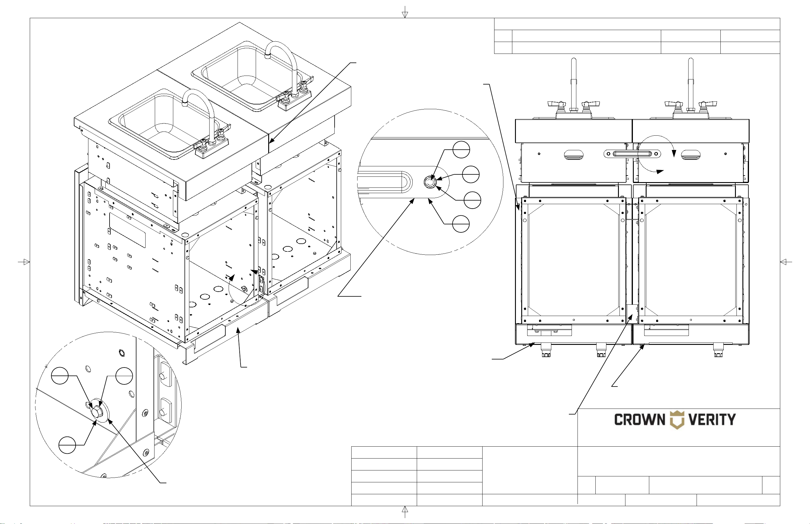
The mounting bracket of the adjacent
cabinet rest on this ledge. This
provides support for the cabinet and
eliminates the need for additional
levelling legs at the attachment point.
Note that this bracket is installed
in the opposite direction of the
bracket in Detail "B"
Note the difference in
bracket used for the
top two locations.
The brackets of the adjacent
cabinet align with these slotted
mounting holes 6 places.
1
4
Note the orientation of the
bracket when installing.
6
2
5
6
3
30
2
30

27
REVISION HISTORY
REV
DESCRIPTION
DATE
APPROVED
TITLE
SIZE
Customer
DWG NO
REV
SCALE SHEET
Finish
N/A
B
ICM-SK Cabinet to ICC90 Cabinet
00
Engineering Release
01/01/2021
Todd Stone
37 Adams Blvd., Brantford, Ontario, N3S 7V8
P: (519) 751-1800 www.crownverity.com
1:7.5
2 of 2
00
IB-ICMSK-ICC90
Crown Verity
K Factor
Weight (Kg)
Gauge
N/A
N/A
N/A
DRAWN BY:
Todd Stone
Material
SS 304
01/01/2021
Dimensions are in inches
Linear Tolerance: +/- .015
Bend Tolerance: +/- .020
Angular Tolerance: +/- 0.5
Radial Tolerance: +/-.005
Copyright 2021 Crown Verity Inc. All rights reserved. Unauthorized duplication is a violation of applicable laws.
D
Connection to attachment
bracket using hardware
provided. 6 places. Do not
tighten until cabinets are levelled
and aligned at the back.
Align the back of
the cabinet flush to
the front face of the
door (not shown).
Door removed
for clarity
In the assembly shown the base
cabinet (initial starting cabinet) would
be put in place and levelled on all four
legs prior to attaching the next cabinet.
The attaching cabinet, would be populated with the attachment brackets. The
bottom attachment bracket would rest on the edge of the base cabinet for
support while the hardware was installed. The hardware would not be
tightened until the attaching cabinet is levelled and flush with the base cabinet.
The attachment brackets provide
structural support for the side of the
cabinet that is attached. Legs are
therefore only required on the opposite
cabinet side.
Detail D
SCALE 1 : 1.88
The brackets are installed to the
cabinet at 4 mounting points
using the hardware provided.
2
30
3
30
4
24

28
REVISION HISTORY
REV
DESCRIPTION
DATE
APPROVED
TITLE
SIZE
Customer
DWG NO
REV
SCALE SHEET
Finish
N/A
B
ICM-SK Cabinet to ICM-SB Cabinet
00
Engineering Release
01/01/2021
Todd Stone
37 Adams Blvd., Brantford, Ontario, N3S 7V8
P: (519) 751-1800 www.crownverity.com
1:7.5
1 of 2
00
IB-ICMSK-ICMSB
Crown Verity
K Factor
Weight (Kg)
Gauge
N/A
N/A
N/A
DRAWN BY:
Todd Stone
Material
SS 304
01/01/2021
Dimensions are in inches
Linear Tolerance: +/- .015
Bend Tolerance: +/- .020
Angular Tolerance: +/- 0.5
Radial Tolerance: +/-.005
Copyright 2021 Crown Verity Inc. All rights reserved. Unauthorized duplication is a violation of applicable laws.
A
Item No. Part Number Qty Description
1 ZCV-EMC-CB-1000 4 Cabinet Connector Bracket Weld Asy
2 Screw : Hex - 0.25 x 0.5 22 Screw : Hex - 0.25 x 0.5
3 Washer : Internal Teeth - 0.25 x 0.025 23 Washer : Internal Teeth - 0.25 x 0.0255
4 Washer : Plain - 0.25 x 0.063 19 Washer : Plain - 0.25 x 0.063
5 Washer : Plain - 0.25 x 0.1 4 Washer : Plain - 0.25 x 0.1
6 ZCV-EMC-CP 1 Connector Plate
7 Screw : Round - 0.25 x 2.5 1 Screw : Round - 0.25 x 2.5
B
C
Detail B
SCALE 1 : 1.88
Note that this bracket is installed
in the opposite direction of the
bracket in Detail "B"
The brackets are installed to the
adjacent cabinet using the
hardware provided 4 places.
Detail C
SCALE 1 : 1.88
Detail A
SCALE 1 : 1.88
The brackets of the adjacent
cabinet align with these
slotted holes 4 places.
The mounting bracket of the adjacent cabinet
rests on this ledge. This provides support for the
cabinet and eliminates the need for additional
levelling legs at the attachment point.
Note the orientation of the
bracket when installing.
5
4
2
22
3
23
1
4
1
4

29
REVISION HISTORY
REV
DESCRIPTION
DATE
APPROVED
TITLE
SIZE
Customer
DWG NO
REV
SCALE SHEET
Finish
N/A
B
ICM-SK Cabinet to ICM-SB Cabinet
00
Engineering Release
01/01/2021
Todd Stone
37 Adams Blvd., Brantford, Ontario, N3S 7V8
P: (519) 751-1800 www.crownverity.com
1:7.5
2 of 2
00
IB-ICMSK-ICMSB
Crown Verity
K Factor
Weight (Kg)
Gauge
N/A
N/A
N/A
DRAWN BY:
Todd Stone
Material
SS 304
01/01/2021
Dimensions are in inches
Linear Tolerance: +/- .015
Bend Tolerance: +/- .020
Angular Tolerance: +/- 0.5
Radial Tolerance: +/-.005
Copyright 2021 Crown Verity Inc. All rights reserved. Unauthorized duplication is a violation of applicable laws.
Align cabinet
flush along the
back seam.
Back panels
removed for clarity
In the assembly shown the base
cabinet (initial starting cabinet)
would be put in place and
levelled on all four legs prior to
attaching the next cabinet.
The attaching cabinet, would be populated with the
attachment brackets. The bottom attachment
bracket would rest on the edge of the base cabinet
for support while the hardware was installed. The
hardware would not be tightened until the attaching
cabinet is levelled and flush with the base cabinet.
The attachment brackets provide
structural support for the side of
the cabinet that is attached. Legs
are therefore only required on the
opposite cabinet side.
D
E
Detail D
SCALE 1 : 1.88
With the side burner face
removed, the side burner is
attached to the adjacent
cabinet at this point with the
hardware provided.
7
1
3
23
4
19
Detail E
SCALE 1 : 1.88
The connector plate is attached to the
side burner at this location. There is a
corresponding mounting point on the
adjacent cabinet. Install the bracket but
do not tighten the hardware until the
cabinets have been aligned and levelled.
2
22
3
23
4
19
Side burner face has been
removed for clarity.

30
REVISION HISTORY
REV
DESCRIPTION
DATE
APPROVED
TITLE
SIZE
Customer
DWG NO
REV
SCALE SHEET
Finish
N/A
B
ICM-SK Cabinet to ICM-SK Cabinet
00
Engineering Release
01/01/2021
Todd Stone
37 Adams Blvd., Brantford, Ontario, N3S 7V8
P: (519) 751-1800 www.crownverity.com
1:7.5
1 of 2
00
IB-ICMSK-ICMSK
Crown Verity
K Factor
Weight (Kg)
Gauge
N/A
N/A
N/A
DRAWN BY:
Todd Stone
Material
SS 304
01/01/2021
Dimensions are in inches
Linear Tolerance: +/- .015
Bend Tolerance: +/- .020
Angular Tolerance: +/- 0.5
Radial Tolerance: +/-.005
Copyright 2021 Crown Verity Inc. All rights reserved. Unauthorized duplication is a violation of applicable laws.
A
Item No. Part Number Qty Description
1 ZCV-EMC-CB-1000 4 Cabinet Connector Bracket Weld Asy
2 Screw : Hex - 0.25 x 0.5 27 Screw : Hex - 0.25 x 0.5
3 Washer : Internal Teeth - 0.25 x 0.025 27 Washer : Internal Teeth - 0.25 x 0.0255
4 Washer : Plain - 0.25 x 0.063 23 Washer : Plain - 0.25 x 0.063
5 Washer : Plain - 0.25 x 0.1 4 Washer : Plain - 0.25 x 0.1
6 ZCV-EMC-CP 1 Connector Plate
7 ZCV-EMC-SM1-1001-1 1 Sink Module Connector Bracket Weld Asy
D
B
C
Detail D
SCALE 1 : 1.88
Note that this bracket is installed
in the opposite direction of the
bracket in Detail "D"
The brackets are installed to the
adjacent cabinet using the
hardware provided 4 places.
The back panel has been
removed for clarity
Detail B
SCALE 1 : 1.88
Detail C
SCALE 1 : 1.88
Detail A
SCALE 1 : 1.88
The brackets of the adjacent
cabinet align with these
slotted holes 4 places.
The mounting bracket of the adjacent cabinet rests on this
ledge. This provides support for the cabinet and eliminates the
need for additional levelling legs at the attachment point.
Note the orientation of the
bracket when installing.
5
4
2
27
3
27
1
4
1
4
7
1
2
27
4
23
3
27
This hardware is used to connect
the corresponding slotted hole in
the adjacent cabinet
31
REVISION HISTORY
REV
DESCRIPTION
DATE
APPROVED
TITLE
SIZE
Customer
DWG NO
REV
SCALE SHEET
Finish
N/A
B
ICM-SK Cabinet to ICM-SK Cabinet
00
Engineering Release
01/01/2021
Todd Stone
37 Adams Blvd., Brantford, Ontario, N3S 7V8
P: (519) 751-1800 www.crownverity.com
1:7.5
2 of 2
00
IB-ICMSK-ICMSK
Crown Verity
K Factor
Weight (Kg)
Gauge
N/A
N/A
N/A
DRAWN BY:
Todd Stone
Material
SS 304
01/01/2021
Dimensions are in inches
Linear Tolerance: +/- .015
Bend Tolerance: +/- .020
Angular Tolerance: +/- 0.5
Radial Tolerance: +/-.005
Copyright 2021 Crown Verity Inc. All rights reserved. Unauthorized duplication is a violation of applicable laws.
F
Connection to attachment bracket using
hardware provided. 4 places. Do not
tighten until cabinets are levelled and
aligned at the back.
Align cabinet
flush along the
back seam.
Back panel
removed for clarity
In the assembly shown the base
cabinet (initial starting cabinet)
would be put in place and
levelled on all four legs prior to
attaching the next cabinet.
The attaching cabinet, would be populated with the attachment
brackets. The bottom attachment bracket would rest on the
edge of the base cabinet for support while the hardware was
installed. The hardware would not be tightened until the
attaching cabinet is levelled and flush with the base cabinet.
The attachment brackets provide structural
support for the side of the cabinet that is
attached. Legs are therfore only required
on the opposite cabinet side.
E
Detail E
SCALE 1 : 1.88
5
4
2
27
3
27
Detail F
SCALE 1 : 1.88
Back panels
removed for clarity
6
1
4
23
3
27
2
27
The connector plate is attached to
the sink at this location. There is a
corresponding mounting point on
the adjacent cabinet. Install the
bracket but do not tighten the
hardware until the cabinets have
been aligned and levelled.

32
REVISION HISTORY
REV
DESCRIPTION
DATE
APPROVED
TITLE
SIZE
Customer
DWG NO
REV
SCALE SHEET
Finish
N/A
B
ICM-SK Cabinet to IFM Fridge
00
Engineering Release
01/01/2021
Todd Stone
37 Adams Blvd., Brantford, Ontario, N3S 7V8
P: (519) 751-1800 www.crownverity.com
1:7.5
1 of 2
00
IB-ICMSK-IFM24
Crown Verity
K Factor
Weight (Kg)
Gauge
N/A
N/A
N/A
DRAWN BY:
Todd Stone
Material
SS 304
01/01/2021
Dimensions are in inches
Linear Tolerance: +/- .015
Bend Tolerance: +/- .020
Angular Tolerance: +/- 0.5
Radial Tolerance: +/-.005
Copyright 2021 Crown Verity Inc. All rights reserved. Unauthorized duplication is a violation of applicable laws.
B
D
Item No. Part Number Qty Description
1 Washer : Internal Teeth - 0.25 x 0.025 18 Washer : Internal Teeth - 0.25 x 0.0255
2 Screw : Hex - 0.25 x 0.5 18 Screw : Hex - 0.25 x 0.5
3 Washer : Plain - 0.25 x 0.1 10 Washer : Plain - 0.25 x 0.1
4 Washer : Plain - 0.25 x 0.063 8 Washer : Plain - 0.25 x 0.063
A
C
Detail B
SCALE 1 : 1.88
Detail A
SCALE 1 : 1.88
The brackets of the fridge
align with these slotted
mounting holes 5 places.
The fridge attaches to the adjacent
cabinet at these threaded insert
locations 5 places.
Detail C
SCALE 1 : 1.88
Detail D
SCALE 1 : 1.88
The upper rear bracket of the fridge aligns
with this threaded mounting hole.
Mounting hardware for
upper rear bracket
2
18
1
18
3
10
1
18
4
8
2
18

33
REVISION HISTORY
REV
DESCRIPTION
DATE
APPROVED
TITLE
SIZE
Customer
DWG NO
REV
SCALE SHEET
Finish
N/A
B
ICM-SK Cabinet to IFM Fridge
00
Engineering Release
01/01/2021
Todd Stone
37 Adams Blvd., Brantford, Ontario, N3S 7V8
P: (519) 751-1800 www.crownverity.com
1:7.5
2 of 2
00
IB-ICMSK-IFM24
Crown Verity
K Factor
Weight (Kg)
Gauge
N/A
N/A
N/A
DRAWN BY:
Todd Stone
Material
SS 304
01/01/2021
Dimensions are in inches
Linear Tolerance: +/- .015
Bend Tolerance: +/- .020
Angular Tolerance: +/- 0.5
Radial Tolerance: +/-.005
Copyright 2021 Crown Verity Inc. All rights reserved. Unauthorized duplication is a violation of applicable laws.
F
Connection to the adjacent cabinet
using hardware provided. 5 places.
Do not tighten until cabinets are
levelled and aligned at the back.
Align the back of
the cabinets flush
along this seam.
Door removed
for clarity
Cabinets connecting to a fridge
require all four legs to be installed.
The fridge does not provide
support for the adjacent cabinet.
E
Detail E
SCALE 1 : 2
Detail F
SCALE 1 : 2
2
18
1
18
4
8
Attach the fridge to the
upper corner of the
adjacent cabinet using
the hardware provided.
Remove the drawer to
access the connection point
at this location
3
10
1
18
2
18

34
REVISION HISTORY
REV
DESCRIPTION
DATE
APPROVED
TITLE
SIZE
Customer
DWG NO
REV
SCALE SHEET
Finish
N/A
B
ICM-SK Sink Cabinet to IGM Grill
00
Engineering Release
01/01/2021
Todd Stone
37 Adams Blvd., Brantford, Ontario, N3S 7V8
P: (519) 751-1800 www.crownverity.com
1:7.5
1 of 2
00
IB-ICMSK-IGM
Crown Verity
K Factor
Weight (Kg)
Gauge
N/A
N/A
N/A
DRAWN BY:
Todd Stone
Material
SS 304
01/01/2021
Dimensions are in inches
Linear Tolerance: +/- .015
Bend Tolerance: +/- .020
Angular Tolerance: +/- 0.5
Radial Tolerance: +/-.005
Copyright 2021 Crown Verity Inc. All rights reserved. Unauthorized duplication is a violation of applicable laws.
A
C
Item No. Part Number Qty Description
1 ZCV-EMC-CB-1000 4 Cabinet Connector Bracket Weld Asy
2 Screw : Hex - 0.25 x 0.5 22 Screw : Hex - 0.25 x 0.5
3 Washer : Internal Teeth - 0.25 x 0.025 23 Washer : Internal Teeth - 0.25 x 0.0255
4 Washer : Plain - 0.25 x 0.063 19 Washer : Plain - 0.25 x 0.063
5 Washer : Plain - 0.25 x 0.1 4 Washer : Plain - 0.25 x 0.1
6 ZCV-EMC-CP 1 Connector Plate
7 Screw : Round - 0.25 x 2.5 1 Screw : Round - 0.25 x 2.5
B
Detail B
SCALE 1 : 1.88
Note that this bracket is installed
in the opposite direction of the
bracket in Detail "A"
The brackets are installed
to the adjacent cabinet
using the hardware
provided 4 places.
Detail A
SCALE 1 : 1.88
The brackets of the
adjacent cabinet align
with these slotted
holes 4 places.
The mounting bracket of the adjacent
cabinet rests on this ledge. This
provides support for the cabinet and
eliminates the need for additional
levelling legs at the attachment point.
Note the
orientation of the
bracket when
installing.
Detail C
SCALE 1 : 1.88
1
4
1
4
5
4
3
23
2
22
Dome has been removed
from grill for clarity

35
REVISION HISTORY
REV
DESCRIPTION
DATE
APPROVED
TITLE
SIZE
Customer
DWG NO
REV
SCALE SHEET
Finish
N/A
B
ICM-SK Sink Cabinet to IGM Grill
00
Engineering Release
01/01/2021
Todd Stone
37 Adams Blvd., Brantford, Ontario, N3S 7V8
P: (519) 751-1800 www.crownverity.com
1:8
2 of 2
00
IB-ICMSK-IGM
Crown Verity
K Factor
Weight (Kg)
Gauge
N/A
N/A
N/A
DRAWN BY:
Todd Stone
Material
SS 304
01/01/2021
Dimensions are in inches
Linear Tolerance: +/- .015
Bend Tolerance: +/- .020
Angular Tolerance: +/- 0.5
Radial Tolerance: +/-.005
Copyright 2021 Crown Verity Inc. All rights reserved. Unauthorized duplication is a violation of applicable laws.
Align cabinet
flush along the
back seam.
Back panels
removed for clarity
In the assembly shown the base
cabinet (initial starting cabinet)
would be put in place and
levelled on all four legs prior to
attaching the next cabinet.
The attaching cabinet, would be populated with the
attachment brackets. The bottom attachment
bracket would rest on the edge of the base cabinet
for support while the hardware was installed. The
hardware would not be tightened until the attaching
cabinet is levelled and flush with the base cabinet.
The attachment brackets
provide structural support for the
side of the cabinet that is
attached. Legs are therefore
only required on the opposite
cabinet side.
D
E
Detail D
SCALE 1 : 1.88
With the grill face removed, the
grill is attached to the adjacent
cabinet at this point with the
hardware provided.
Detail E
SCALE 1 : 1.88
The connector plate is attached to
the grill at this location. There is a
corresponding mounting point on
the adjacent cabinet. Install the
bracket but do not tighten the
hardware until the cabinets have
been aligned and levelled.
Grill face has been
removed for clarity.
7
1
3
23
4
19
4
19
3
23
2
22

36
STORAGE

37
REVISION HISTORY
REV
DESCRIPTION
DATE
APPROVED
TITLE
SIZE
Customer
DWG NO
REV
SCALE SHEET
Finish
N/A
B
ICM Cabinet to ICC45 Cabinet
00
Engineering Release
01/01/2021
Todd Stone
37 Adams Blvd., Brantford, Ontario, N3S 7V8
P: (519) 751-1800 www.crownverity.com
1:7.5
1 of 2
00
IB-ICM-ICC45
Crown Verity
K Factor
Weight (Kg)
Gauge
N/A
N/A
N/A
DRAWN BY:
Todd Stone
Material
SS 304
01/01/2021
Dimensions are in inches
Linear Tolerance: +/- .015
Bend Tolerance: +/- .020
Angular Tolerance: +/- 0.5
Radial Tolerance: +/-.005
Copyright 2021 Crown Verity Inc. All rights reserved. Unauthorized duplication is a violation of applicable laws.
B
Item No. Part Number Qty Description
1 Screw : Hex - 0.25 x 0.5 6 Screw : Hex - 0.25 x 0.5
2 Washer : Internal Teeth - 0.25 x 0.025 6 Washer : Internal Teeth - 0.25 x 0.0255
3 Washer : Plain - 0.25 x 0.1 6 Washer : Plain - 0.25 x 0.1
A
Detail B
SCALE 1 : 1.88
Detail A
SCALE 1 : 1.88
The threaded inserts of the corner
cabinet align with these slotted
mounting holes 6 places.
The cabinet attaches to the corner cabinet
at these threaded insert locations 6 places.
38
REVISION HISTORY
REV
DESCRIPTION
DATE
APPROVED
TITLE
SIZE
Customer
DWG NO
REV
SCALE SHEET
Finish
N/A
B
ICM Cabinet to ICC45 Cabinet
00
Engineering Release
01/01/2021
Todd Stone
37 Adams Blvd., Brantford, Ontario, N3S 7V8
P: (519) 751-1800 www.crownverity.com
1:7.5
2 of 2
00
IB-ICM-ICC45
Crown Verity
K Factor
Weight (Kg)
Gauge
N/A
N/A
N/A
DRAWN BY:
Todd Stone
Material
SS 304
01/01/2021
Dimensions are in inches
Linear Tolerance: +/- .015
Bend Tolerance: +/- .020
Angular Tolerance: +/- 0.5
Radial Tolerance: +/-.005
Copyright 2021 Crown Verity Inc. All rights reserved. Unauthorized duplication is a violation of applicable laws.
Connection to the corner cabinet
using hardware provided. 6 places.
Do not tighten until cabinets are
levelled and aligned at the back.
Align the back of
the cabinets flush
along this seam.
Door removed
for clarity
In the assembly shown the base
cabinet (initial starting cabinet)
would be put in place and
levelled on all four legs prior to
attaching the next cabinet.
The tops of the adjacent
cabinets should be at the same
height when levelled.
C
Detail C
SCALE 1 : 1.88
2
6
1
6
3
6
39
REVISION HISTORY
REV
DESCRIPTION
DATE
APPROVED
TITLE
SIZE
Customer
DWG NO
REV
SCALE SHEET
Finish
N/A
B
ICM Cabinet to ICC90 Cabinet
00
Engineering Release
01/01/2021
Todd Stone
37 Adams Blvd., Brantford, Ontario, N3S 7V8
P: (519) 751-1800 www.crownverity.com
1:7.5
1 of 2
00
IB-ICM-ICC90
Crown Verity
K Factor
Weight (Kg)
Gauge
N/A
N/A
N/A
DRAWN BY:
Todd Stone
Material
SS 304
01/01/2021
Dimensions are in inches
Linear Tolerance: +/- .015
Bend Tolerance: +/- .020
Angular Tolerance: +/- 0.5
Radial Tolerance: +/-.005
Copyright 2021 Crown Verity Inc. All rights reserved. Unauthorized duplication is a violation of applicable laws.
B
A
Item No. Part Number Qty Description
1 ZCV-EMC-CB-1000 6 Cabinet Connector Bracket Weld Asy
2 Screw : Hex - 0.25 x 0.5 30 Screw : Hex - 0.25 x 0.5
3 Washer : Internal Teeth - 0.25 x 0.025 30 Washer : Internal Teeth - 0.25 x 0.0255
4 Washer : Plain - 0.25 x 0.063 24 Washer : Plain - 0.25 x 0.063
5 Washer : Plain - 0.25 x 0.1 6 Washer : Plain - 0.25 x 0.1
C
Detail B
SCALE 1 : 1.88
Detail C
SCALE 1 : 1.88
Detail A
SCALE 1 : 1.88
The mounting bracket of the adjacent
cabinet rest on this ledge. This
provides support for the cabinet and
eliminates the need for additional
levelling legs at the attachment point.
Note that this bracket is installed
in the opposite direction of the
bracket in Detail "B"
Note the orientation
of the bracket, 4
places.
5
6
3
30
2
30
The brackets of the adjacent
cabinet align with these slotted
mounting holes 6 places.
1
6
Note the orientation of the
bracket when installing.
40
REVISION HISTORY
REV
DESCRIPTION
DATE
APPROVED
TITLE
SIZE
Customer
DWG NO
REV
SCALE SHEET
Finish
N/A
B
ICM Cabinet to ICC90 Cabinet
00
Engineering Release
01/01/2021
Todd Stone
37 Adams Blvd., Brantford, Ontario, N3S 7V8
P: (519) 751-1800 www.crownverity.com
1:7.5
2 of 2
00
IB-ICM-ICC90
Crown Verity
K Factor
Weight (Kg)
Gauge
N/A
N/A
N/A
DRAWN BY:
Todd Stone
Material
SS 304
01/01/2021
Dimensions are in inches
Linear Tolerance: +/- .015
Bend Tolerance: +/- .020
Angular Tolerance: +/- 0.5
Radial Tolerance: +/-.005
Copyright 2021 Crown Verity Inc. All rights reserved. Unauthorized duplication is a violation of applicable laws.
D
Connection to attachment
bracket using hardware
provided. 6 places. Do not
tighten until cabinets are levelled
and aligned at the back.
Align the back of
the cabinet flush to
the front face of the
door (not shown).
Door removed
for clarity
In the assembly shown the base
cabinet (initial starting cabinet)
would be put in place and
levelled on all four legs prior to
attaching the next cabinet.
The attaching cabinet, would be populated with the
attachment brackets. The bottom attachment
bracket would rest on the edge of the base cabinet
for support while the hardware was installed. The
hardware would not be tightened until the attaching
cabinet is levelled and flush with the base cabinet.
The attachment brackets provide
structural support for the side of the
cabinet that is attached. Legs are
therefore only required on the opposite
cabinet side.
The tops of the adjacent
cabinets should be at the same
height when levelled.
Detail D
SCALE 1 : 1.88
The brackets are installed to the
cabinet at 4 mounting points
using the hardware provided.
2
30
3
30
4
24

41
REVISION HISTORY
REV
DESCRIPTION
DATE
APPROVED
TITLE
SIZE
Customer
DWG NO
REV
SCALE SHEET
Finish
N/A
B
ICM Cabinet to ICM Cabinet
00
Engineering Release
01/01/2021
Todd Stone
37 Adams Blvd., Brantford, Ontario, N3S 7V8
P: (519) 751-1800 www.crownverity.com
1:7.5
1 of 2
00
IB-ICM-ICM
Crown Verity
K Factor
Weight (Kg)
Gauge
N/A
N/A
N/A
DRAWN BY:
Todd Stone
Material
SS 304
01/01/2021
Dimensions are in inches
Linear Tolerance: +/- .015
Bend Tolerance: +/- .020
Angular Tolerance: +/- 0.5
Radial Tolerance: +/-.005
Copyright 2021 Crown Verity Inc. All rights reserved. Unauthorized duplication is a violation of applicable laws.
B
A
Item No. Part Number Qty Description
1 ZCV-EMC-CB-1000 6 Cabinet Connector Bracket Weld Asy
2 Screw : Hex - 0.25 x 0.5 30 Screw : Hex - 0.25 x 0.5
3 Washer : Internal Teeth - 0.25 x 0.025 30 Washer : Internal Teeth - 0.25 x 0.0255
4 Washer : Plain - 0.25 x 0.063 24 Washer : Plain - 0.25 x 0.063
5 Washer : Plain - 0.25 x 0.1 6 Washer : Plain - 0.25 x 0.1
D
C
Detail B
SCALE 1 : 1.88
Detail D
SCALE 1 : 1.88
Detail A
SCALE 1 : 1.88
Detail C
SCALE 1 : 1.88
The mounting bracket of the adjacent
cabinet rest on this ledge. This
provides support for the cabinet and
eliminates the need for additional
levelling legs at the attachment point.
Note that this bracket is installed
in the opposite direction of the
bracket in Detail "B"
Note the orientation
of the bracket, 4
places.
5
6
3
30
2
30
4
24
3
30
2
30
The brackets are installed to the
cabinet at 4 mounting points
using the hardware provided.
The brackets of the adjacent
cabinet align with these slotted
mounting holes 6 places.
The back panel has
been removed for clarity
1
6
Note the orientation of the
bracket when installing.

42
REVISION HISTORY
REV
DESCRIPTION
DATE
APPROVED
TITLE
SIZE
Customer
DWG NO
REV
SCALE SHEET
Finish
N/A
B
ICM Cabinet to ICM Cabinet
00
Engineering Release
01/01/2021
Todd Stone
37 Adams Blvd., Brantford, Ontario, N3S 7V8
P: (519) 751-1800 www.crownverity.com
1:7.5
2 of 2
00
IB-ICM-ICM
Crown Verity
K Factor
Weight (Kg)
Gauge
N/A
N/A
N/A
DRAWN BY:
Todd Stone
Material
SS 304
01/01/2021
Dimensions are in inches
Linear Tolerance: +/- .015
Bend Tolerance: +/- .020
Angular Tolerance: +/- 0.5
Radial Tolerance: +/-.005
Copyright 2021 Crown Verity Inc. All rights reserved. Unauthorized duplication is a violation of applicable laws.
Connection to attachment
bracket using hardware
provided. 6 places. Do not
tighten until cabinets are levelled
and aligned at the back.
Align cabinet
flush along the
back seam and
top surface.
Back panel
removed for clarity
In the assembly shown the base
cabinet (initial starting cabinet)
would be put in place and
levelled on all four legs prior to
attaching the next cabinet.
The attaching cabinet, would be populated with the
attachment brackets. The bottom attachment
bracket would rest on the edge of the base cabinet
for support while the hardware was installed. The
hardware would not be tightened until the attaching
cabinet is levelled and flush with the base cabinet.
The attachment brackets provide
structural support for the side of the
cabinet that is attached. Legs are
therefore only required on the opposite
cabinet side.
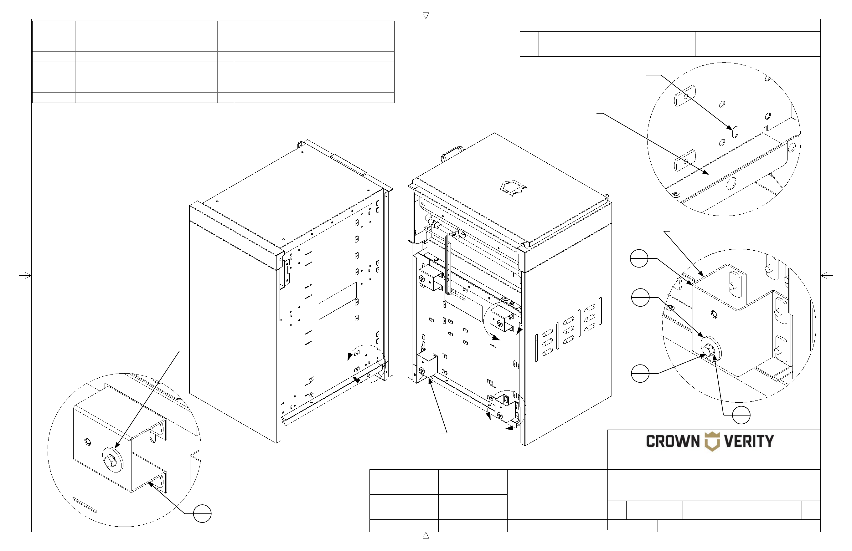
43
REVISION HISTORY
REV
DESCRIPTION
DATE
APPROVED
TITLE
SIZE
Customer
DWG NO
REV
SCALE SHEET
Finish
N/A
B
ICM Cabinet to ICM-SB Cabinet
00
Engineering Release
01/01/2021
Todd Stone
37 Adams Blvd., Brantford, Ontario, N3S 7V8
P: (519) 751-1800 www.crownverity.com
1:7.5
1 of 2
00
IB-ICM-ICM-SB
Crown Verity
K Factor
Weight (Kg)
Gauge
N/A
N/A
N/A
DRAWN BY:
Todd Stone
Material
SS 304
01/01/2021
Dimensions are in inches
Linear Tolerance: +/- .015
Bend Tolerance: +/- .020
Angular Tolerance: +/- 0.5
Radial Tolerance: +/-.005
Copyright 2021 Crown Verity Inc. All rights reserved. Unauthorized duplication is a violation of applicable laws.
A
Item No. Part Number Qty Description
1 ZCV-EMC-CB-1000 4 Cabinet Connector Bracket Weld Asy
2 Screw : Hex - 0.25 x 0.5 22 Screw : Hex - 0.25 x 0.5
3 Washer : Internal Teeth - 0.25 x 0.025 23 Washer : Internal Teeth - 0.25 x 0.0255
4 Washer : Plain - 0.25 x 0.063 19 Washer : Plain - 0.25 x 0.063
5 Washer : Plain - 0.25 x 0.1 4 Washer : Plain - 0.25 x 0.1
6 ZCV-EMC-CP 1 Connector Plate
7 Screw : Round - 0.25 x 2.5 1 Screw : Round - 0.25 x 2.5
B
C
Detail B
SCALE 1 : 1.88
Note that this bracket is installed
in the opposite direction of the
bracket in Detail "B"
The brackets are installed to the
adjacent cabinet using the
hardware provided 4 places.
Detail C
SCALE 1 : 1.88
Detail A
SCALE 1 : 1.88
The brackets of the adjacent
cabinet align with these
slotted holes 4 places.
The mounting bracket of the adjacent cabinet
rests on this ledge. This provides support for the
cabinet and eliminates the need for additional
levelling legs at the attachment point.
Note the orientation of the
bracket when installing.
5
4
2
22
3
23
1
4
1
4

44
REVISION HISTORY
REV
DESCRIPTION
DATE
APPROVED
TITLE
SIZE
Customer
DWG NO
REV
SCALE SHEET
Finish
N/A
B
ICM Cabinet to ICM-SB Cabinet
00
Engineering Release
01/01/2021
Todd Stone
37 Adams Blvd., Brantford, Ontario, N3S 7V8
P: (519) 751-1800 www.crownverity.com
1:7.5
2 of 2
00
IB-ICM-ICM-SB
Crown Verity
K Factor
Weight (Kg)
Gauge
N/A
N/A
N/A
DRAWN BY:
Todd Stone
Material
SS 304
01/01/2021
Dimensions are in inches
Linear Tolerance: +/- .015
Bend Tolerance: +/- .020
Angular Tolerance: +/- 0.5
Radial Tolerance: +/-.005
Copyright 2021 Crown Verity Inc. All rights reserved. Unauthorized duplication is a violation of applicable laws.
Align cabinet
flush along the
back seam.
Back panels
removed for clarity
In the assembly shown the base
cabinet (initial starting cabinet)
would be put in place and
levelled on all four legs prior to
attaching the next cabinet.
The attaching cabinet, would be populated with the
attachment brackets. The bottom attachment
bracket would rest on the edge of the base cabinet
for support while the hardware was installed. The
hardware would not be tightened until the attaching
cabinet is levelled and flush with the base cabinet.
The attachment brackets
provide structural support for the
side of the cabinet that is
attached. Legs are therefore
only required on the opposite
cabinet side.
D
E
Detail D
SCALE 1 : 1.88
With the side burner face
removed, the side burner is
attached to the adjacent
cabinet at this point with the
hardware provided.
7
1
3
23
4
19
Detail E
SCALE 1 : 1.88
The connector plate is attached to the
side burner at this location. There is a
corresponding mounting point on the
adjacent cabinet. Install the bracket but
do not tighten the hardware until the
cabinets have been aligned and levelled.
2
22
3
23
4
19
Side burner face and cabinet door
have been removed for clarity.
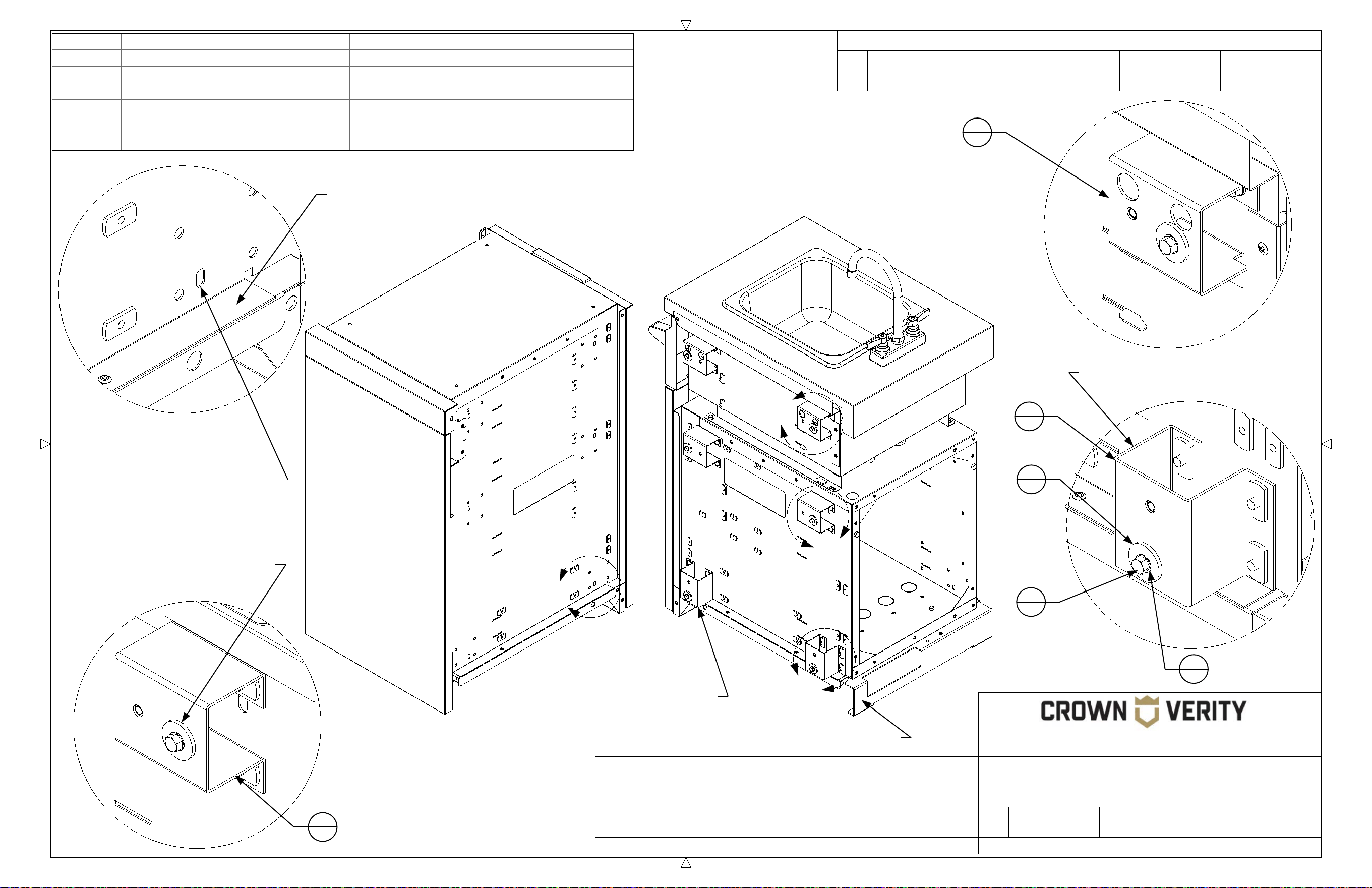
45
REVISION HISTORY
REV
DESCRIPTION
DATE
APPROVED
TITLE
SIZE
Customer
DWG NO
REV
SCALE SHEET
Finish
N/A
B
ICM Cabinet to ICM-SK Cabinet
00
Engineering Release
01/01/2021
Todd Stone
37 Adams Blvd., Brantford, Ontario, N3S 7V8
P: (519) 751-1800 www.crownverity.com
1:7.5
1 of 2
00
IB-ICM-ICM-SK
Crown Verity
K Factor
Weight (Kg)
Gauge
N/A
N/A
N/A
DRAWN BY:
Todd Stone
Material
SS 304
01/01/2021
Dimensions are in inches
Linear Tolerance: +/- .015
Bend Tolerance: +/- .020
Angular Tolerance: +/- 0.5
Radial Tolerance: +/-.005
Copyright 2021 Crown Verity Inc. All rights reserved. Unauthorized duplication is a violation of applicable laws.
A
Item No. Part Number Qty Description
1 ZCV-EMC-CB-1000 4 Cabinet Connector Bracket Weld Asy
2 Screw : Hex - 0.25 x 0.5 30 Screw : Hex - 0.25 x 0.5
3 Washer : Internal Teeth - 0.25 x 0.025 30 Washer : Internal Teeth - 0.25 x 0.0255
4 Washer : Plain - 0.25 x 0.063 24 Washer : Plain - 0.25 x 0.063
5 Washer : Plain - 0.25 x 0.1 6 Washer : Plain - 0.25 x 0.1
6 ZCV-EMC-SM1-1001-1 2 Sink Module Connector Bracket Weld Asy
D
B
C
Detail D
SCALE 1 : 1.88
Note that this bracket is installed
in the opposite direction of the
bracket in Detail "D"
The brackets are installed to the
adjacent cabinet using the
hardware provided 6 places.
The back panel has been
removed for clarity
Detail B
SCALE 1 : 1.88
Detail C
SCALE 1 : 1.88
Detail A
SCALE 1 : 1.88
The brackets of the adjacent
cabinet align with these
slotted holes 6 places.
The mounting bracket of the adjacent cabinet rests on this
ledge. This provides support for the cabinet and eliminates the
need for additional levelling legs at the attachment point.
Note the orientation of the
bracket when installing.
6
2
5
6
2
30
3
30
1
4
1
4

46
REVISION HISTORY
REV
DESCRIPTION
DATE
APPROVED
TITLE
SIZE
Customer
DWG NO
REV
SCALE SHEET
Finish
N/A
B
ICM Cabinet to ICM-SK Cabinet
00
Engineering Release
01/01/2021
Todd Stone
37 Adams Blvd., Brantford, Ontario, N3S 7V8
P: (519) 751-1800 www.crownverity.com
1:7.5
2 of 2
00
IB-ICM-ICM-SK
Crown Verity
K Factor
Weight (Kg)
Gauge
N/A
N/A
N/A
DRAWN BY:
Todd Stone
Material
SS 304
01/01/2021
Dimensions are in inches
Linear Tolerance: +/- .015
Bend Tolerance: +/- .020
Angular Tolerance: +/- 0.5
Radial Tolerance: +/-.005
Copyright 2021 Crown Verity Inc. All rights reserved. Unauthorized duplication is a violation of applicable laws.
Connection to attachment bracket using
hardware provided. 6 places. Do not
tighten until cabinets are levelled and
aligned at the back.
Align cabinet
flush along the
back seam.
Back panel
removed for clarity
In the assembly shown the base
cabinet (initial starting cabinet)
would be put in place and
levelled on all four legs prior to
attaching the next cabinet.
The attaching cabinet, would be populated with the attachment
brackets. The bottom attachment bracket would rest on the
edge of the base cabinet for support while the hardware was
installed. The hardware would not be tightened until the
attaching cabinet is levelled and flush with the base cabinet.
The attachment brackets provide structural
support for the side of the cabinet that is
attached. Legs are therfore only required
on the opposite cabinet side.
E
Detail E
SCALE 1 : 1.88
5
6
2
30
3
30

47
REVISION HISTORY
REV
DESCRIPTION
DATE
APPROVED
TITLE
SIZE
Customer
DWG NO
REV
SCALE SHEET
Finish
N/A
B
ICM Cabinet to IFM Fridge
00
Engineering Release
01/01/2021
Todd Stone
37 Adams Blvd., Brantford, Ontario, N3S 7V8
P: (519) 751-1800 www.crownverity.com
1:7.5
1 of 2
00
IB-ICM-IFM24
Crown Verity
K Factor
Weight (Kg)
Gauge
N/A
N/A
N/A
DRAWN BY:
Todd Stone
Material
SS 304
01/01/2021
Dimensions are in inches
Linear Tolerance: +/- .015
Bend Tolerance: +/- .020
Angular Tolerance: +/- 0.5
Radial Tolerance: +/-.005
Copyright 2021 Crown Verity Inc. All rights reserved. Unauthorized duplication is a violation of applicable laws.
B
D
Item No. Part Number Qty Description
1 Washer : Internal Teeth - 0.25 x 0.025 18 Washer : Internal Teeth - 0.25 x 0.0255
2 Screw : Hex - 0.25 x 0.5 18 Screw : Hex - 0.25 x 0.5
3 Washer : Plain - 0.25 x 0.1 10 Washer : Plain - 0.25 x 0.1
4 Washer : Plain - 0.25 x 0.063 8 Washer : Plain - 0.25 x 0.063
A
C
Detail B
SCALE 1 : 1.88
Detail A
SCALE 1 : 1.88
The brackets of the fridge
align with these slotted
mounting holes 5 places.
The fridge attaches to the adjacent
cabinet at these threaded insert
locations 5 places.
Detail C
SCALE 1 : 1.88
Detail D
SCALE 1 : 1.88
The upper rear bracket of the fridge aligns
with these mounting holes 3 places.
Mounting hardware for
upper rear bracket
2
18
1
18
3
10
2
18
1
18
4
8

48
REVISION HISTORY
REV
DESCRIPTION
DATE
APPROVED
TITLE
SIZE
Customer
DWG NO
REV
SCALE SHEET
Finish
N/A
B
ICM Cabinet to IFM Fridge
00
Engineering Release
01/01/2021
Todd Stone
37 Adams Blvd., Brantford, Ontario, N3S 7V8
P: (519) 751-1800 www.crownverity.com
1:7.5
2 of 2
00
IB-ICM-IFM24
Crown Verity
K Factor
Weight (Kg)
Gauge
N/A
N/A
N/A
DRAWN BY:
Todd Stone
Material
SS 304
01/01/2021
Dimensions are in inches
Linear Tolerance: +/- .015
Bend Tolerance: +/- .020
Angular Tolerance: +/- 0.5
Radial Tolerance: +/-.005
Copyright 2021 Crown Verity Inc. All rights reserved. Unauthorized duplication is a violation of applicable laws.
F
Connection to the adjacent cabinet
using hardware provided. 5 places.
Do not tighten until cabinets are
levelled and aligned at the back.
Align the back of
the cabinets flush
along this seam.
Door removed
for clarity
Cabinets connecting to a fridge
require all four legs to be installed.
The fridge does not provide
support for the adjacent cabinet.
The top of the adjacent
cabinet should be at
the same height as the
horizontal channels
when levelled.
E
Detail E
SCALE 1 : 2
3
10
1
18
2
18
Detail F
SCALE 1 : 2
2
18
1
18
4
8
Attach the fridge to the
upper corner of the
adjacent cabinet using
the hardware provided.

49
REVISION HISTORY
REV
DESCRIPTION
DATE
APPROVED
TITLE
SIZE
Customer
DWG NO
REV
SCALE SHEET
Finish
N/A
B
ICM Cabinet to IGM Grill
00
Engineering Release
01/01/2021
Todd Stone
37 Adams Blvd., Brantford, Ontario, N3S 7V8
P: (519) 751-1800 www.crownverity.com
1:7.5
1 of 2
00
IB-ICM-IGM
Crown Verity
K Factor
Weight (Kg)
Gauge
N/A
N/A
N/A
DRAWN BY:
Todd Stone
Material
SS 304
01/01/2021
Dimensions are in inches
Linear Tolerance: +/- .015
Bend Tolerance: +/- .020
Angular Tolerance: +/- 0.5
Radial Tolerance: +/-.005
Copyright 2021 Crown Verity Inc. All rights reserved. Unauthorized duplication is a violation of applicable laws.
A
C
Item No. Part Number Qty Description
1 ZCV-EMC-CB-1000 4 Cabinet Connector Bracket Weld Asy
2 Screw : Hex - 0.25 x 0.5 22 Screw : Hex - 0.25 x 0.5
3 Washer : Internal Teeth - 0.25 x 0.025 23 Washer : Internal Teeth - 0.25 x 0.0255
4 Washer : Plain - 0.25 x 0.063 19 Washer : Plain - 0.25 x 0.063
5 Washer : Plain - 0.25 x 0.1 4 Washer : Plain - 0.25 x 0.1
6 ZCV-EMC-CP 1 Connector Plate
7 Screw : Round - 0.25 x 2.5 1 Screw : Round - 0.25 x 2.5
B
Detail B
SCALE 1 : 1.88
Note that this bracket is installed
in the opposite direction of the
bracket in Detail "A"
The brackets are installed
to the adjacent cabinet
using the hardware
provided 4 places.
Detail A
SCALE 1 : 1.88
The brackets of the
adjacent cabinet align
with these slotted
holes 4 places.
The mounting bracket of the adjacent
cabinet rests on this ledge. This
provides support for the cabinet and
eliminates the need for additional
levelling legs at the attachment point.
Note the
orientation of the
bracket when
installing.
Detail C
SCALE 1 : 1.88
1
4
1
4
5
4
3
23
2
22
Dome has been removed
from grill for clarity
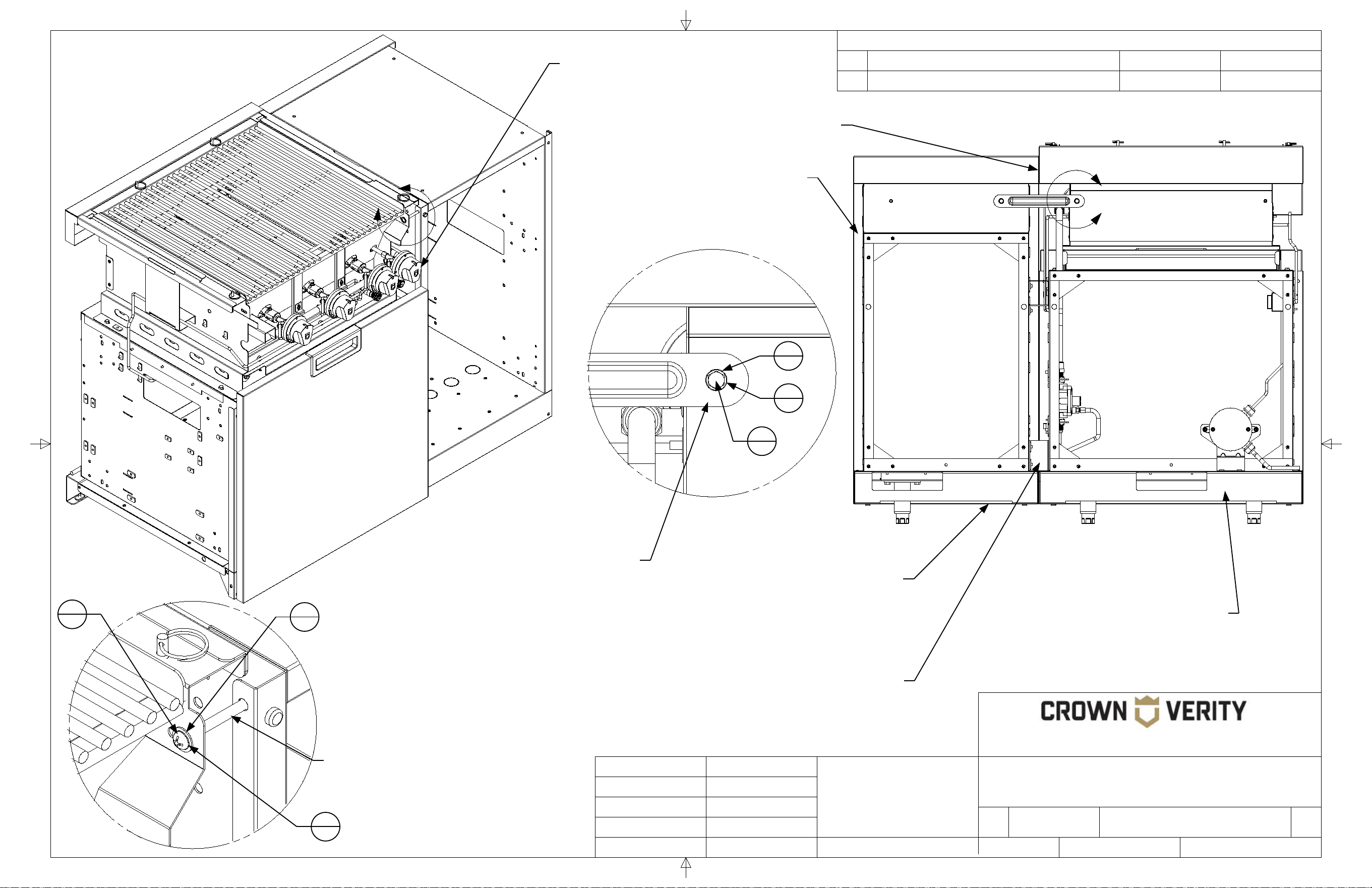
50
REVISION HISTORY
REV
DESCRIPTION
DATE
APPROVED
TITLE
SIZE
Customer
DWG NO
REV
SCALE SHEET
Finish
N/A
B
ICM Cabinet to IGM Grill
00
Engineering Release
01/01/2021
Todd Stone
37 Adams Blvd., Brantford, Ontario, N3S 7V8
P: (519) 751-1800 www.crownverity.com
1:8
2 of 2
00
IB-ICM-IGM
Crown Verity
K Factor
Weight (Kg)
Gauge
N/A
N/A
N/A
DRAWN BY:
Todd Stone
Material
SS 304
01/01/2021
Dimensions are in inches
Linear Tolerance: +/- .015
Bend Tolerance: +/- .020
Angular Tolerance: +/- 0.5
Radial Tolerance: +/-.005
Copyright 2021 Crown Verity Inc. All rights reserved. Unauthorized duplication is a violation of applicable laws.
Align cabinet
flush along the
back seam.
Back panels
removed for clarity
In the assembly shown the base
cabinet (initial starting cabinet)
would be put in place and
levelled on all four legs prior to
attaching the next cabinet.
The attaching cabinet, would be populated with the
attachment brackets. The bottom attachment
bracket would rest on the edge of the base cabinet
for support while the hardware was installed. The
hardware would not be tightened until the attaching
cabinet is levelled and flush with the base cabinet.
The attachment brackets
provide structural support for the
side of the cabinet that is
attached. Legs are therefore
only required on the opposite
cabinet side.
D
E
Detail D
SCALE 1 : 1.88
With the grill face removed, the
grill is attached to the adjacent
cabinet at this point with the
hardware provided.
Detail E
SCALE 1 : 1.88
The connector plate is attached to
the grill at this location. There is a
corresponding mounting point on
the adjacent cabinet. Install the
bracket but do not tighten the
hardware until the cabinets have
been aligned and levelled.
Grill face and cabinet door have
been removed for clarity.
7
1
3
23
4
19
4
19
3
23
2
22

51
END PANELS
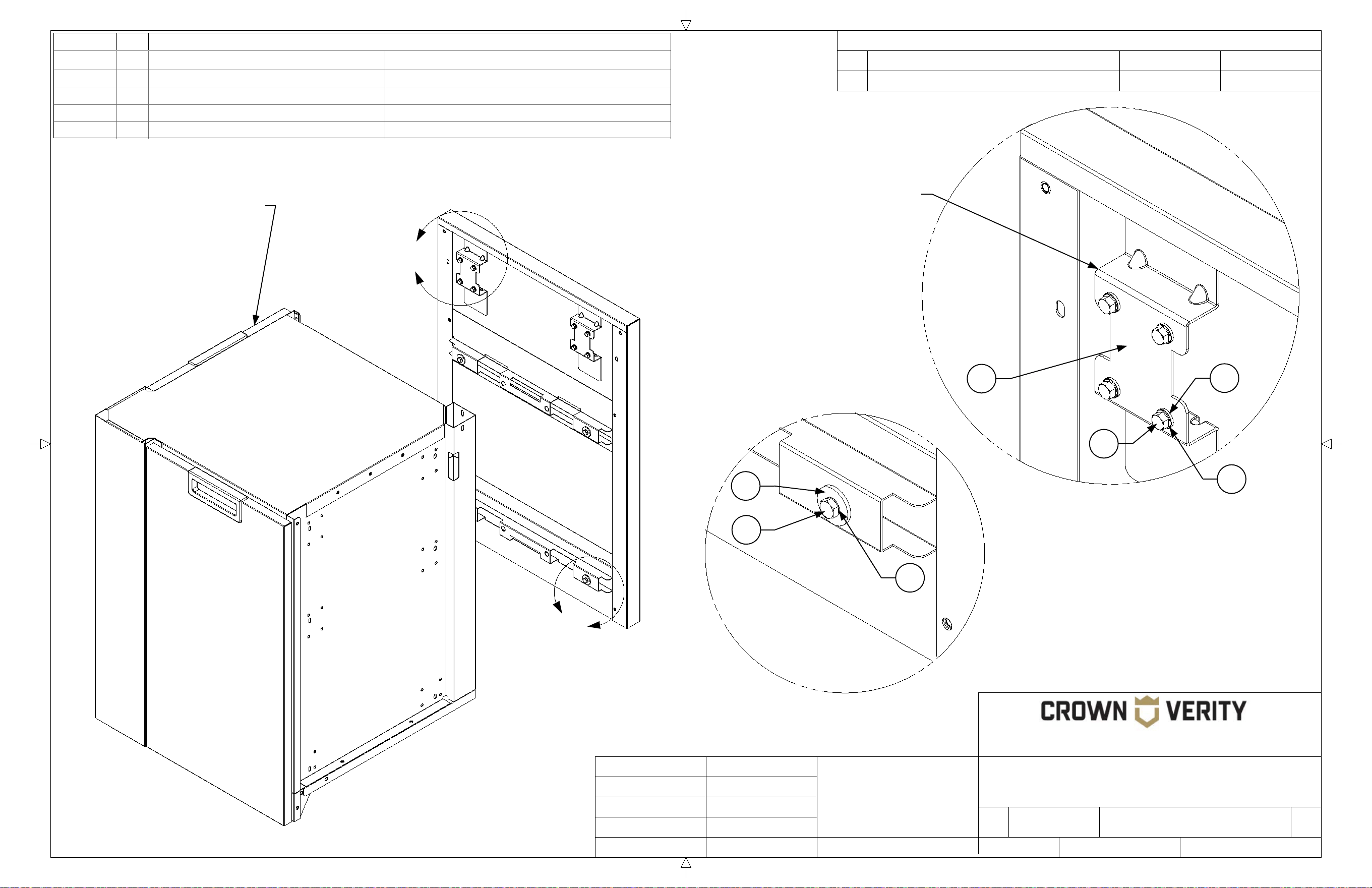
52
REVISION HISTORY
REV
DESCRIPTION
DATE
APPROVED
TITLE
SIZE
Customer
DWG NO
REV
SCALE SHEET
Finish
N/A
B
End Panel to 90 Degree Corner
Bracket Package
-
Engineering Release
01/01/2020
Todd Stone
37 Adams Blvd., Brantford, Ontario, N3S 7V8
P: (519) 751-1800 www.crownverity.com
1:7.5
1 of 1
-
IB-EP-90
Crown Verity
K Factor
Weight (Kg)
Gauge
N/A
N/A
N/A
DRAWN BY:
Todd Stone
Material
SS 304
01/01/2020
Dimensions are in inches
Linear Tolerance: +/- .015
Bend Tolerance: +/- .020
Angular Tolerance: +/- 0.5
Radial Tolerance: +/-.005
Copyright 2020 Crown Verity Inc. All rights reserved. Unauthorized duplication is a violation of applicable laws.
A
B
Detail A
SCALE 1 : 1.88
Detail B
SCALE 1 : 1.88
TYPICAL 4 PLACES
Item No. Qty Part Number Description
1 12 Bolt : Hex - 0.25 x 0.5 Bolt : Hex - 0.25 x 0.5
2 4 Washer : Plain - 0.25 x 0.1 Washer : Plain - 0.25 x 0.1
3 12 Washer : Internal Teeth - 0.25 x 0.0255 Washer : Internal Teeth - 0.25 x 0.0255
4 2 ZCV-EMC-EPB-1000 Universal End Panel Bracket Weld Asy
5 8 Washer : Plain - 0.25 x 0.063 Washer : Plain - 0.25 x 0.063
1
3
2
For proper alignment with the
end panel, the end panel
should be flush to the face of
the door at this position
TYPICAL 2 PLACES
4
5
1
3
The ICC90 corner cabinet requires the shorter
end panel IEP-SH. The Universal End Panel
Bracket will need to be oriented with the
shorter blade facing up in this application.

53
REVISION HISTORY
REV
DESCRIPTION
DATE
APPROVED
TITLE
SIZE
Customer
DWG NO
REV
SCALE SHEET
Finish
N/A
B
-
Engineering Release
01/01/2020
Todd Stone
37 Adams Blvd., Brantford, Ontario, N3S 7V8
P: (519) 751-1800 www.crownverity.com
1:7.5
2 of 2
-
Crown Verity
K Factor
Weight (Kg)
Gauge
N/A
N/A
N/A
DRAWN BY:
Todd Stone
Material
SS 304
01/01/2020
Dimensions are in inches
Linear Tolerance: +/- .015
Bend Tolerance: +/- .020
Angular Tolerance: +/- 0.5
Radial Tolerance: +/-.005
Copyright 2020 Crown Verity Inc. All rights reserved. Unauthorized duplication is a violation of applicable laws.
TYPICAL 4 PLACES
End Panel to 90 Degree Corner
Bracket Package
IB-EP-90
C
D
Detail C
SCALE 1 : 1.88
Detail D
SCALE 1 : 1.88
E
Detail E
SCALE 1 : 1.88
The end panel is attached to the
corner cabinet four places.
Position the hardware but do not
tighten it until the end panel is
aligned with the corner cabinet.
The end panel bracket connects to the
corner cabinet at this position. The
shorter blade of the bracket hooks
behind the end panel to hold it in place.
See detail "E" for more details.
TYPICAL 2 PLACES
TYPICAL 2 PLACES
A portion of the end
panel has been
removed for clarity
The end panel bracket is oriented
with the shorter blade pointing up.
The blade "sandwiches" the formed
inner flange of the end panel
against the top edge of the corner
cabinet to hold it in place.

54
REVISION HISTORY
REV
DESCRIPTION
DATE
APPROVED
TITLE
SIZE
Customer
DWG NO
REV
SCALE SHEET
Finish
N/A
B
End Panel to Storage Cabinet
-
Engineering Release
01/01/2020
Todd Stone
37 Adams Blvd., Brantford, Ontario, N3S 7V8
P: (519) 751-1800 www.crownverity.com
1:7.5
1 of 2
-
IB-EP-ICM
Crown Verity
K Factor
Weight (Kg)
Gauge
N/A
N/A
N/A
DRAWN BY:
Todd Stone
Material
SS 304
01/01/2020
Dimensions are in inches
Linear Tolerance: +/- .015
Bend Tolerance: +/- .020
Angular Tolerance: +/- 0.5
Radial Tolerance: +/-.005
Copyright 2020 Crown Verity Inc. All rights reserved. Unauthorized duplication is a violation of applicable laws.
A
C
B
Detail A
SCALE 1 : 1.88
Detail C
SCALE 1 : 1.88
Detail B
SCALE 1 : 1.88
TYPICAL 4 PLACES
Item No. Qty Part Number Description
1 1 ZCV-EMC-CPEP-1 Connector Plate for End Panel Weld Asy
2 5 Washer : Plain - 0.25 x 0.1 Washer : Plain - 0.25 x 0.1
3 10 Bolt : Hex - 0.25 x 0.5 Bolt : Hex - 0.25 x 0.5
4 10 Washer : Internal Teeth - 0.25 x 0.0255 Washer : Internal Teeth - 0.25 x 0.0255
5 5 Washer : Plain - 0.25 x 0.063 Washer : Plain - 0.25 x 0.063
6 1 ZCV-EMC-EPB-1000 Universal End Panel Bracket Weld Asy
3
4
2
3
4
5
3
4
2
For proper alignment with the end panel,
the end panel should be flush to the rear of
the storage cabinet at this position
The ICM storage cabinet without the cutting
board option requires the shorter end panel
IEP-SH. The Universal End Panel Bracket
will be oriented with the shorter blade facing
up in this application. When installed. the
bracket hooks behind the formed flange of
the end panel and "sandwiches" the end
panel to the top edge of the storage cabinet.
6
5
4
3
1
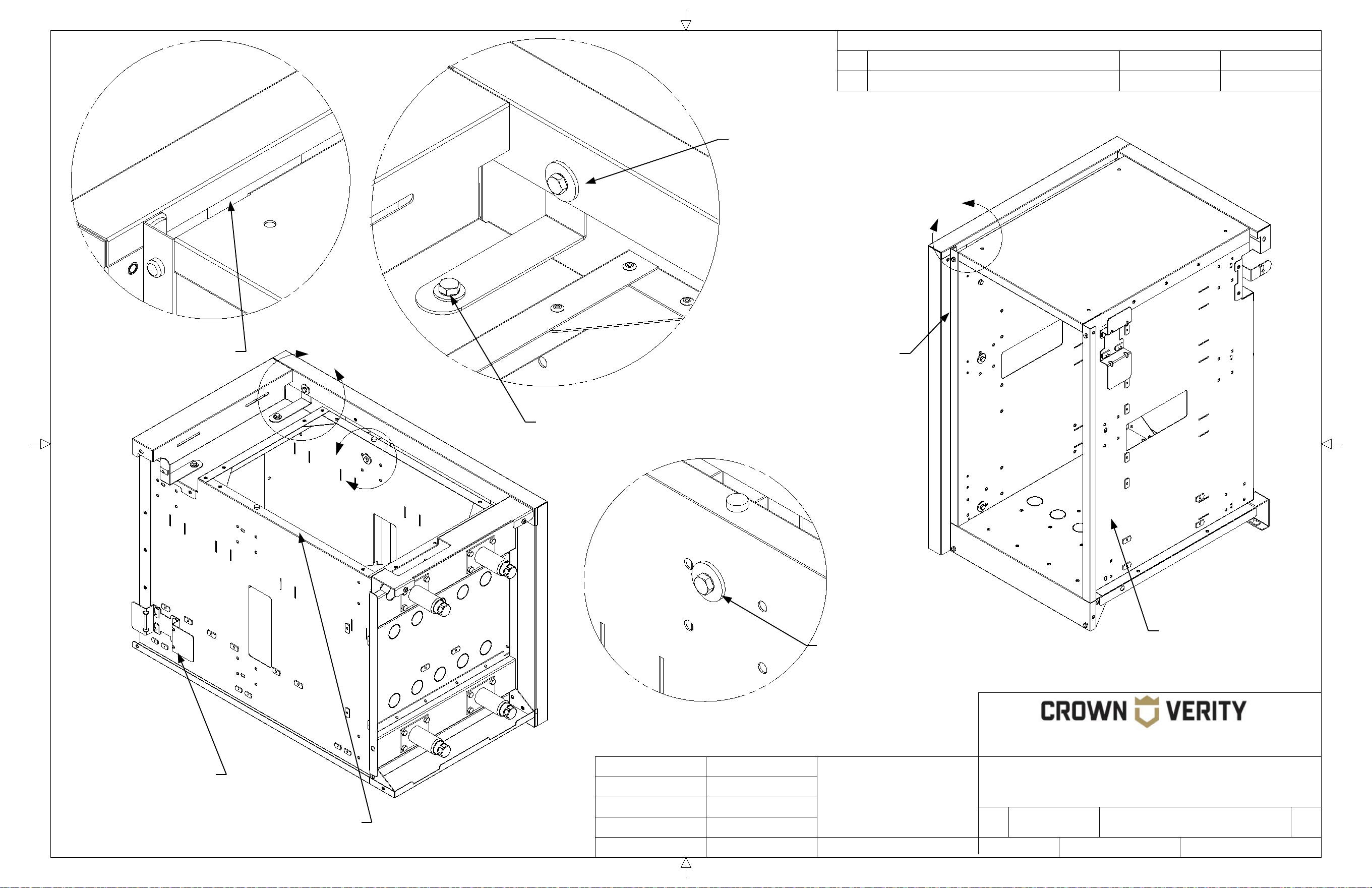
55
REVISION HISTORY
REV
DESCRIPTION
DATE
APPROVED
TITLE
SIZE
Customer
DWG NO
REV
SCALE SHEET
Finish
N/A
B
-
Engineering Release
01/01/2020
Todd Stone
37 Adams Blvd., Brantford, Ontario, N3S 7V8
P: (519) 751-1800 www.crownverity.com
1:7.5
2 of 2
-
Crown Verity
K Factor
Weight (Kg)
Gauge
N/A
N/A
N/A
DRAWN BY:
Todd Stone
Material
SS 304
01/01/2020
Dimensions are in inches
Linear Tolerance: +/- .015
Bend Tolerance: +/- .020
Angular Tolerance: +/- 0.5
Radial Tolerance: +/-.005
Copyright 2020 Crown Verity Inc. All rights reserved. Unauthorized duplication is a violation of applicable laws.
D
E
F
Detail D
SCALE 1 : 1.88
Detail E
SCALE 1 : 1.88
Detail F
SCALE 1 : 1.88
TYPICAL 4 PLACES
Storage cabinet
shown with front door
removed for clarity
Storage Cabinet
shown with back panel
removed for clarity
The end panel bracket
shown is positioned behind
the formed flange of the end
panel when installed.
The end panel bracket connects the
rear of the storage cabinet to the
end panel at this position. The
bracket hooks behind the panel and
is bolted in place from the front.
The end panel bracket is attached to the back
of the storage cabinet at this position. Ensure
the end panel is pushed tight against the side
of the cabinet before tightening the bolt.
The end panel is attached to the
storage cabinet at four locations.
Position the hardware but do night
tighten it until the end panel is aligned
with the cabinet
End Panel to Storage Cabinet
IB-EP-ICM
Storage cabinet
shown with end panel
removed for clarity.
End panel bracket is
installed with hardware
provided from the inside
of the cabinet as shown
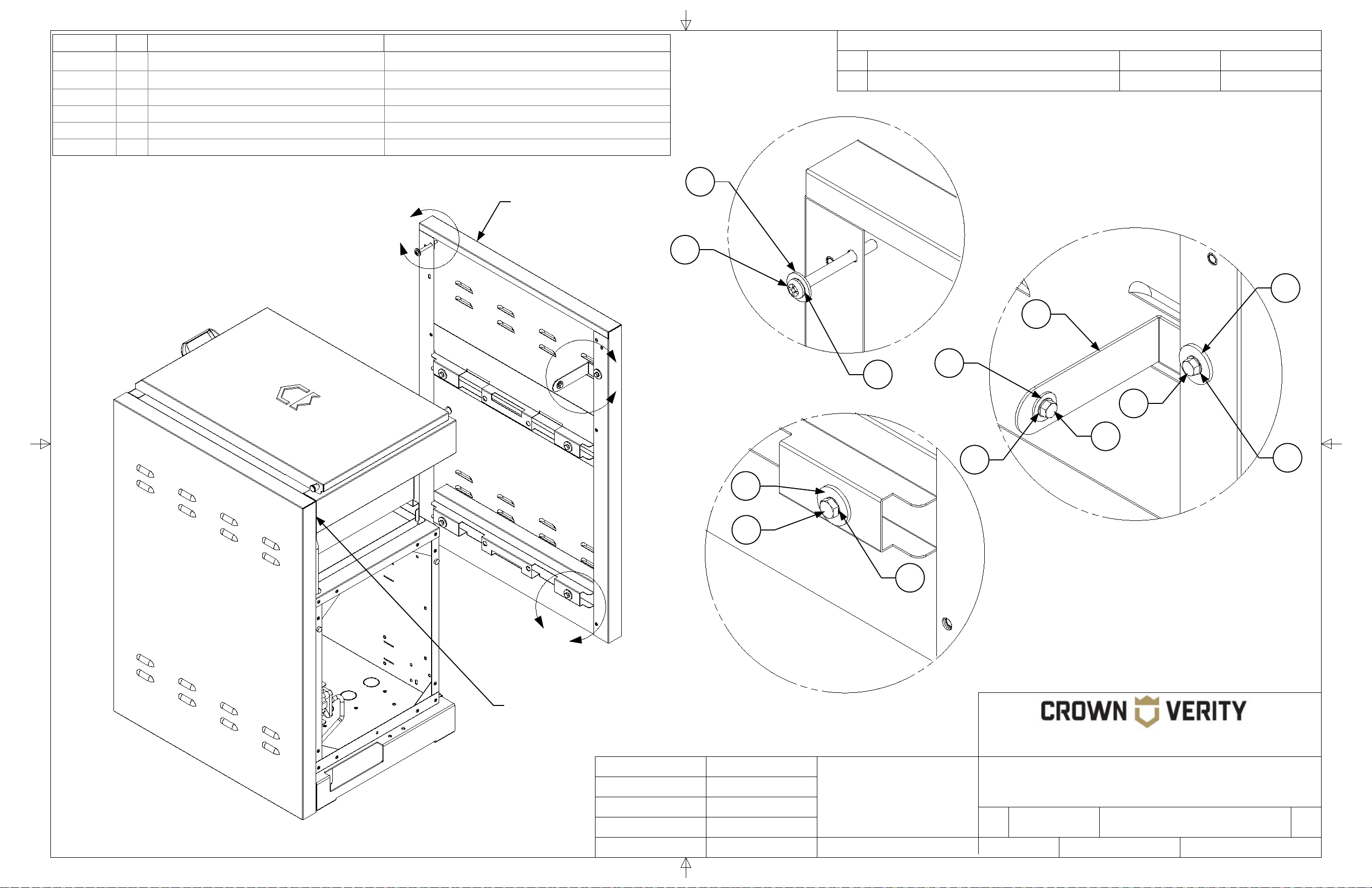
56
REVISION HISTORY
REV
DESCRIPTION
DATE
APPROVED
TITLE
SIZE
Customer
DWG NO
REV
SCALE SHEET
Finish
N/A
B
End Panel to Side Burner
Bracket Package
-
Engineering Release
01/01/2020
Todd Stone
37 Adams Blvd., Brantford, Ontario, N3S 7V8
P: (519) 751-1800 www.crownverity.com
1:7.5
1 of 2
-
IB-EP-ICMSB
Crown Verity
K Factor
Weight (Kg)
Gauge
N/A
N/A
N/A
DRAWN BY:
Todd Stone
Material
SS 304
01/01/2020
Dimensions are in inches
Linear Tolerance: +/- .015
Bend Tolerance: +/- .020
Angular Tolerance: +/- 0.5
Radial Tolerance: +/-.005
Copyright 2020 Crown Verity Inc. All rights reserved. Unauthorized duplication is a violation of applicable laws.
A
C
B
Detail A
SCALE 1 : 1.88
Detail C
SCALE 1 : 1.88
Detail B
SCALE 1 : 1.88
TYPICAL 4 PLACES
Item No. Qty Part Number Description
1 5 Washer : Plain - 0.25 x 0.1 Washer : Plain - 0.25 x 0.1
2 6 Bolt : Hex - 0.25 x 0.5 Bolt : Hex - 0.25 x 0.5
3 8 Washer : Internal Teeth - 0.25 x 0.0255 Washer : Internal Teeth - 0.25 x 0.0255
4 1 ZCV-EMC-CPEP-1 Connector Plate for End Panel Weld Asy
5 2 Washer : Plain - 0.25 x 0.063 Washer : Plain - 0.25 x 0.063
6 1 Screw : Pan - 0.25 x 2.5 Screw : Pan - 0.25 x 2.5
2
3
1
For proper alignment with the end panel,
the end panel should be flush to the rear of
the side burner at the position
3
1
3
2
5
3
2
4
6
5
The ICM-SB Side
Burner requires the
longer end panel IEP-FH

57
REVISION HISTORY
REV
DESCRIPTION
DATE
APPROVED
TITLE
SIZE
Customer
DWG NO
REV
SCALE SHEET
Finish
N/A
B
-
Engineering Release
01/01/2020
Todd Stone
37 Adams Blvd., Brantford, Ontario, N3S 7V8
P: (519) 751-1800 www.crownverity.com
1:7.5
2 of 2
-
Crown Verity
K Factor
Weight (Kg)
Gauge
N/A
N/A
N/A
DRAWN BY:
Todd Stone
Material
SS 304
01/01/2020
Dimensions are in inches
Linear Tolerance: +/- .015
Bend Tolerance: +/- .020
Angular Tolerance: +/- 0.5
Radial Tolerance: +/-.005
Copyright 2020 Crown Verity Inc. All rights reserved. Unauthorized duplication is a violation of applicable laws.
D
E
F
Detail D
SCALE 1 : 1.88
Detail E
SCALE 1 : 1.88
Detail F
SCALE 1 : 1.88
TYPICAL 4 PLACES
Side Burner shown
with front face
removed for clarity
Side Burner shown
with back panel
removed for clarity
The end panel is connected
to the top front of the side
burner at this position. Do
not overtighten the screw.
The end panel bracket connects the
rear of the side burner to the end
panel at this position. The bracket
hooks behind the panel and is
bolted in place from the front.
The end panel bracket is attached to the back
of the side burner at this position. Ensure the
end panel is pushed tight against the side of
the side burner before tightening the bolt.
The end panel is attached to the side
burner cabinet four places. Position the
hardware but do not tighten it until the
end panel is aligned with the side burner
End Panel to Side Burner
Bracket Package
IB-EP-ICMSB

58
REVISION HISTORY
REV
DESCRIPTION
DATE
APPROVED
TITLE
SIZE
Customer
DWG NO
REV
SCALE SHEET
Finish
N/A
B
End Panel to Sink
Bracket Package
-
Engineering Release
01/01/2020
Todd Stone
37 Adams Blvd., Brantford, Ontario, N3S 7V8
P: (519) 751-1800 www.crownverity.com
1:7.5
1 of 1
-
IB-EP-ICMSK
Crown Verity
K Factor
Weight (Kg)
Gauge
N/A
N/A
N/A
DRAWN BY:
Todd Stone
Material
SS 304
01/01/2020
Dimensions are in inches
Linear Tolerance: +/- .015
Bend Tolerance: +/- .020
Angular Tolerance: +/- 0.5
Radial Tolerance: +/-.005
Copyright 2020 Crown Verity Inc. All rights reserved. Unauthorized duplication is a violation of applicable laws.
A
C
B
Detail A
SCALE 1 : 1.88
Detail C
SCALE 1 : 1.88
Detail B
SCALE 1 : 1.88
TYPICAL 4 PLACES
Item No. Qty Part Number Description
1 1 ZCV-EMC-CPEP-1 Connector Plate for End Panel Weld Asy
2 10 Bolt : Hex - 0.25 x 0.5 Bolt : Hex - 0.25 x 0.5
3 5 Washer : Plain - 0.25 x 0.1 Washer : Plain - 0.25 x 0.1
4 10 Washer : Internal Teeth - 0.25 x 0.0255 Washer : Internal Teeth - 0.25 x 0.0255
5 5 Washer : Plain - 0.25 x 0.063 Washer : Plain - 0.25 x 0.063
6 1 ZCV-EMC-EPSB-1000 End Panel Sink Bracket
2
4
3
2
4
5
2
4
3
For proper alignment with the end panel,
the end panel should be flush to the rear of
the sink at this position
6
2
The ICM-SK Sink
Cabinet requires
the longer end
panel IEP-FH.

59
REVISION HISTORY
REV
DESCRIPTION
DATE
APPROVED
TITLE
SIZE
Customer
DWG NO
REV
SCALE SHEET
Finish
N/A
B
-
Engineering Release
01/01/2020
Todd Stone
37 Adams Blvd., Brantford, Ontario, N3S 7V8
P: (519) 751-1800 www.crownverity.com
1:7.5
2 of 2
-
Crown Verity
K Factor
Weight (Kg)
Gauge
N/A
N/A
N/A
DRAWN BY:
Todd Stone
Material
SS 304
01/01/2020
Dimensions are in inches
Linear Tolerance: +/- .015
Bend Tolerance: +/- .020
Angular Tolerance: +/- 0.5
Radial Tolerance: +/-.005
Copyright 2020 Crown Verity Inc. All rights reserved. Unauthorized duplication is a violation of applicable laws.
D
E
F
Detail D
SCALE 1 : 1.88
Detail E
SCALE 1 : 1.88
Detail F
SCALE 1 : 1.88
TYPICAL 4 PLACES
Sink shown with the end
panel removed for clarity
Sink shown with back
panel removed for clarity
The end panel sink bracket
is attached to the front of the
upper sink cabinet 4 places
as shown.
The end panel bracket connects
the rear of the sink to the end
panel at this position. The bracket
hooks behind the panel and is
bolted in place from the front.
The end panel bracket is attached to the back
of the sink at this position. Ensure the end
panel is pushed tight against the side of the
sink before tightening the bolt.
The end panel is attached to the sink
cabinet four places. Position the
hardware but do night tighten it until
the end panel is aligned with the sink
End Panel to Sink
Bracket Package
IB-EP-ICMSK

60
REVISION HISTORY
REV
DESCRIPTION
DATE
APPROVED
TITLE
SIZE
Customer
DWG NO
REV
SCALE SHEET
Finish
N/A
B
End Panel to Fridge Module Package
-
Engineering Release
01/01/2020
Todd Stone
37 Adams Blvd., Brantford, Ontario, N3S 7V8
P: (519) 751-1800 www.crownverity.com
1:9
1 of 1
-
IB-EP-RF
Crown Verity
K Factor
Weight (Kg)
Gauge
N/A
N/A
N/A
DRAWN BY:
Todd Stone
Material
SS 304
01/01/2020
Dimensions are in inches
Linear Tolerance: +/- .015
Bend Tolerance: +/- .020
Angular Tolerance: +/- 0.5
Radial Tolerance: +/-.005
Copyright 2020 Crown Verity Inc. All rights reserved. Unauthorized duplication is a violation of applicable laws.
A
B
Detail A
SCALE 1 : 1.88
Detail B
SCALE 1 : 1.88
For proper alignment with the
end panel, the end panel should
be flush to the rear of the fridge
module at this position
The ICM-FM requires
the Shorter end panel
IEP-SH.
Item No. Qty Part Number Description
1 1 ICM-FM-3 Fridge Module for LH End Panel
2 3 Washer : Plain - 0.25 x 0.063 Washer : Plain - 0.25 x 0.063
3 3 Washer : Internal Teeth - 0.25 x 0.0255 Washer : Internal Teeth - 0.25 x 0.0255
4 3 Screw : Hex - 0.25 x 0.5 Screw : Hex - 0.25 x 0.5
The back panel has
been removed from
the fridge module
for clarity
The end panel rests on the four hook details
shown. Once in place and aligned with the back
of the fridge module, the screws can be tightened
The end panel brackets for the
fridge module are shown on both
sides for clarity. The standard
configuration would have cabinet
mounting brackets opposite the
end panel brackets.
4
3
2
4
3
2
1
Connect the fridge module bracket
to the end panel two places. Do not
tighten in place until the end panel
has been aligned with the back of
the fridge module
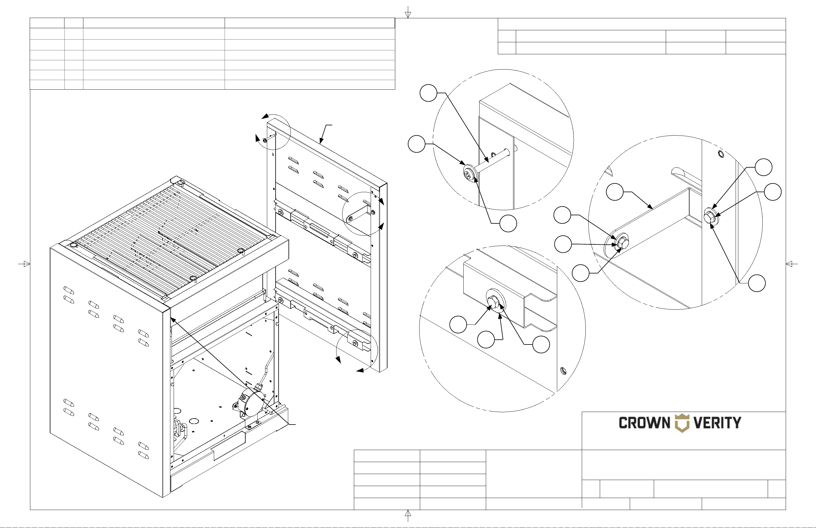
61
REVISION HISTORY
REV
DESCRIPTION
DATE
APPROVED
TITLE
SIZE
Customer
DWG NO
REV
SCALE SHEET
Finish
N/A
B
End Panel to Grill Bracket Package
-
Engineering Release
01/01/2020
Todd Stone
37 Adams Blvd., Brantford, Ontario, N3S 7V8
P: (519) 751-1800 www.crownverity.com
1:7.5
1 of 2
-
IB-EP-IGM
Crown Verity
K Factor
Weight (Kg)
Gauge
N/A
N/A
N/A
DRAWN BY:
Todd Stone
Material
SS 304
01/01/2020
Dimensions are in inches
Linear Tolerance: +/- .015
Bend Tolerance: +/- .020
Angular Tolerance: +/- 0.5
Radial Tolerance: +/-.005
Copyright 2020 Crown Verity Inc. All rights reserved. Unauthorized duplication is a violation of applicable laws.
A
C
B
Detail A
SCALE 1 : 1.88
Detail C
SCALE 1 : 1.88
Detail B
SCALE 1 : 1.88
TYPICAL 4 PLACES
For proper alignment with the end panel,
the end panel should be flush to the rear of
the grill at the position
The IGM Grill Cabinets
require the longer end
panel IEP-FH.
Item No. Qty Part Number Description
1 4 Washer : Plain - 0.25 x 0.1 Washer : Plain - 0.25 x 0.1
2 1 Screw : Pan - 0.25 x 2.5 Screw : Pan - 0.25 x 2.5
3 2 ZCV-EMC-CPEP-1 Connector Plate for End Panel Weld Asy
4 7 Bolt : Hex - 0.25 x 0.5 Bolt : Hex - 0.25 x 0.5
5 8 Washer : Internal Teeth - 0.25 x 0.0255 Washer : Internal Teeth - 0.25 x 0.0255
6 4 Washer : Plain - 0.25 x 0.063 Washer : Plain - 0.25 x 0.063
4
2
5
1
3
6
5
6
5
4
6
5
4
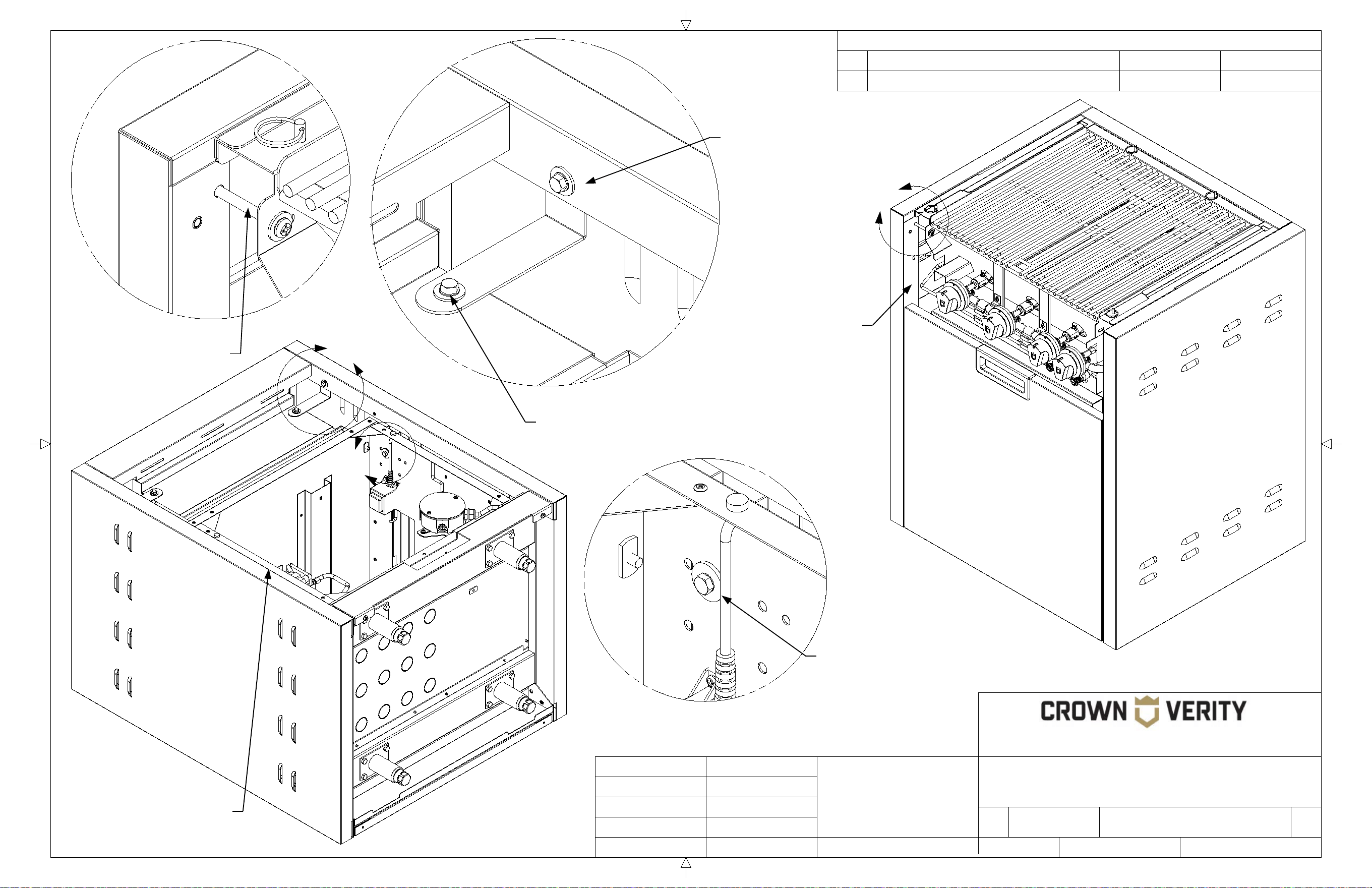
62
REVISION HISTORY
REV
DESCRIPTION
DATE
APPROVED
TITLE
SIZE
Customer
DWG NO
REV
SCALE SHEET
Finish
N/A
B
End Panel to Grill Bracket Package
-
Engineering Release
01/01/2020
Todd Stone
37 Adams Blvd., Brantford, Ontario, N3S 7V8
P: (519) 751-1800 www.crownverity.com
1:7.5
2 of 2
-
IB-EP-IGM
Crown Verity
K Factor
Weight (Kg)
Gauge
N/A
N/A
N/A
DRAWN BY:
Todd Stone
Material
SS 304
01/01/2020
Dimensions are in inches
Linear Tolerance: +/- .015
Bend Tolerance: +/- .020
Angular Tolerance: +/- 0.5
Radial Tolerance: +/-.005
Copyright 2020 Crown Verity Inc. All rights reserved. Unauthorized duplication is a violation of applicable laws.
D
E
F
Detail D
SCALE 1 : 1.88
Detail E
SCALE 1 : 1.88
Detail F
SCALE 1 : 1.88
TYPICAL 4 PLACES
Grill shown with front
face removed for
clarity
Grill shown with back
panel removed for
clarity
The end panel is connected
to the top front of the grill at
this position. Do not
overtighten the screw.
The end panel bracket connects
the rear of the grill to the end panel
at this position. The bracket hooks
behind the panel and is bolted in
place from the front.
The end panel bracket is attached to the back
of the grill at this position. Ensure the end
panel is pushed tight against the side of the
grill before tightening the bolt.
The end panel is attached to the grill
cabinet four places. Position the
hardware but do night tighten it until
the end panel is aligned with the grill

63
REVISION HISTORY
REV
DESCRIPTION
DATE
APPROVED
TITLE
SIZE
Customer
DWG NO
REV
SCALE SHEET
Finish
N/A
B
End Panel to Storage Cabinet
with Cutting Board Option
-
Engineering Release
01/01/2020
Todd Stone
37 Adams Blvd., Brantford, Ontario, N3S 7V8
P: (519) 751-1800 www.crownverity.com
1:7.5
1 of 1
-
IB-EP-ICM
Crown Verity
K Factor
Weight (Kg)
Gauge
N/A
N/A
N/A
DRAWN BY:
Todd Stone
Material
SS 304
01/01/2020
Dimensions are in inches
Linear Tolerance: +/- .015
Bend Tolerance: +/- .020
Angular Tolerance: +/- 0.5
Radial Tolerance: +/-.005
Copyright 2020 Crown Verity Inc. All rights reserved. Unauthorized duplication is a violation of applicable laws.
A
C
B
Detail A
SCALE 1 : 1.88
Detail C
SCALE 1 : 1.88
Detail B
SCALE 1 : 1.88
TYPICAL 4 PLACES
Item No. Qty Part Number Description
1 1 ZCV-EMC-CPEP-1 Connector Plate for End Panel Weld Asy
2 10 Bolt : Hex - 0.25 x 0.5 Bolt : Hex - 0.25 x 0.5
3 5 Washer : Plain - 0.25 x 0.1 Washer : Plain - 0.25 x 0.1
4 10 Washer : Internal Teeth - 0.25 x 0.0255 Washer : Internal Teeth - 0.25 x 0.0255
5 5 Washer : Plain - 0.25 x 0.063 Washer : Plain - 0.25 x 0.063
6 1 ZCV-EMC-EPB-1000 Universal End Panel Bracket Weld Asy
2
4
3
2
4
5
2
4
3
For proper alignment with the end panel,
the end panel should be flush to the rear of
the storage cabinet at this position
ICM-CUTBOARD Option
The ICM storage cabinet with the
cutting board option requires the
longer end panel IEP-FH. The
Universal End Panel Bracket will be
oriented with the longer blade facing
up in this application.
6
5
4
2
1
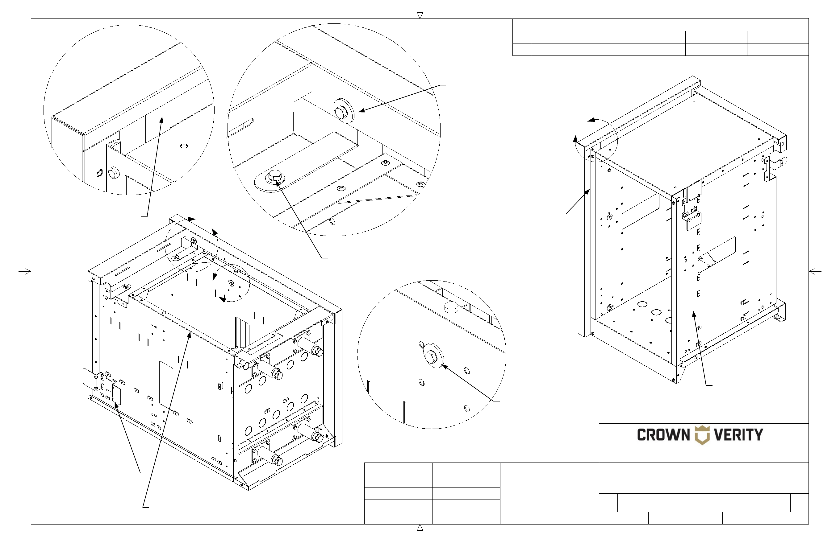
64
REVISION HISTORY
REV
DESCRIPTION
DATE
APPROVED
TITLE
SIZE
Customer
DWG NO
REV
SCALE SHEET
Finish
N/A
B
-
Engineering Release
01/01/2020
Todd Stone
37 Adams Blvd., Brantford, Ontario, N3S 7V8
P: (519) 751-1800 www.crownverity.com
1:7.5
2 of 2
-
Crown Verity
K Factor
Weight (Kg)
Gauge
N/A
N/A
N/A
DRAWN BY:
Todd Stone
Material
SS 304
01/01/2020
Dimensions are in inches
Linear Tolerance: +/- .015
Bend Tolerance: +/- .020
Angular Tolerance: +/- 0.5
Radial Tolerance: +/-.005
Copyright 2020 Crown Verity Inc. All rights reserved. Unauthorized duplication is a violation of applicable laws.
D
E
F
Detail D
SCALE 1 : 1.88
Detail E
SCALE 1 : 1.88
Detail F
SCALE 1 : 1.88
TYPICAL 4 PLACES
Storage cabinet
shown with front door
and cutting board
removed for clarity
Storage cabinet shown
with back panel
removed for clarity
The end panel bracket
shown is positioned behind
the formed flange of the end
panel when installed.
The end panel bracket connects the
rear of the storage cabinet to the
end panel at this position. The
bracket hooks behind the panel
and is bolted in place from the front.
The end panel bracket is attached to the back
of the storage cabinet at this position. Ensure
the end panel is pushed tight against the side of
the storage cabinet before tightening the bolt.
The end panel is attached to the storage
cabinet four places. Position the
hardware but do night tighten it until the
end panel is aligned with the cabinet.
End Panel to Storage Cabinet
with Cutting Board Option
IB-EP-ICM
End panel bracket is
installed with hardware
provided from the inside
of the cabinet as shown
Storage cabinet
shown with end panel
removed for clarity