

© 2018 GeoVision, Inc. All rights reserved.
Under the copyright laws, this manual may not be copied, in whole or in
part, without the written consent of GeoVision.
Every effort has been made to ensure that the information in this manual is
accurate. GeoVision, Inc. makes no expressed or implied warranty of any
kind and assumes no responsibility for errors or omissions. No liability is
assumed for incidental or consequential damages arising from the use of
the information or products contained herein. Features and specifications
are subject to change without notice.
Note: no memory card slot or local
storage function for Argentina.
GeoVision, Inc.
9F, No. 246, Sec. 1, Neihu Rd.,
Neihu District, Taipei, Taiwan
Tel: +886-2-8797-8377
Fax: +886-2-8797-8335
http://www.geovision.com.tw
Trademarks used in this manual: GeoVision, the GeoVision logo and GV
series products are trademarks of GeoVision, Inc. Windows is the
registered trademark of Microsoft Corporation.
July 2018

i
Caution
Risk of explosion if battery is replaced by an incorrect type.
Dispose of used batteries according to the instructions.
Safety Notice
The GV-IPCAM uses a Lithium battery as the power supply for its internal
real-time clock (RTC). The battery should not be replaced unless required!
If the battery does need replacing, please observe the following:
Danger of Explosion if battery is incorrectly replaced
Replace only with the same or equivalent battery, as recommended by
the manufacturer
Dispose of used batteries according to the manufacturer's instructions

ii
Contents
Caution.................................................................................i
Safety Notice .......................................................................i
Options ............................................................................. vi
Creating GV-IP Camera’s Login Credentials................ vii
Note for Adjusting Focus and Zoom............................ viii
Note for Installing Camera Outdoor................................ix
Note for Closing the Bullet Camera Cover ......................x
Note for Silica Gel Bags ....................................................x
Note for Waterproofing Failures......................................xi
Chapter 1 Bullet Camera (Part I)......................................1
1.1 Packing List..............................................................................3
1.2 Overview ..................................................................................4
1.3 Installation ................................................................................5
1.3.1 Connecting the Camera ...............................................7
1.3.2 Adjusting the Angles ..................................................11
1.3.3 Adjusting Lens and Inserting a Memory Card.............15
1.3.4 Installing the Sun-Shield Cover ..................................18
1.4 Loading Factory Default..........................................................19
1.4.1 Using the Web Interface.............................................19
1.4.2 Directly on the Camera ..............................................20
Chapter 2 Bullet Camera (Part II)...................................21
2.1 Packing List............................................................................24
2.2 Overview ................................................................................26

iii
2.3 Installation ..............................................................................29
2.4 Connecting the Camera..........................................................36
Chapter 3 Bullet Camera (Part III)..................................39
3.1 Packing List............................................................................40
3.2 Overview ................................................................................41
3.3 Installation ..............................................................................42
3.3.1 Adjusting the Angles ..................................................46
3.3.2 Adjusting Lens ...........................................................48
3.4 Connecting the Camera..........................................................49
3.4.1 Wire Definition ...........................................................49
3.4.2. Power Connection.....................................................51
3.5 Loading Factory Default..........................................................53
3.5.1. Using the Web Interface............................................53
3.5.2. Directly on the Camera .............................................53
Chapter 4 Ultra Bullet Camera.......................................54
4.1 Packing List............................................................................56
4.2 Overview ................................................................................57
4.3 Installation ..............................................................................59
4.3.1 Waterproofing the Cable ............................................64
4.3.2 Connecting the Camera .............................................66
4.4 Loading Factory Default..........................................................69
4.4.1 Using the Web Interface.............................................69
4.4.2 Directly on the Camera ..............................................69
Chapter 5 Target Bullet Camera (Part I)........................70
5.1 Packing List............................................................................71
5.2 Overview ................................................................................72
5.3 Installation ..............................................................................73
5.4 Connecting the Camera..........................................................77
5.4.1 Wire Definition ...........................................................77
5.4.2 Power Connection......................................................78

iv
5.5 Loading Factory Default..........................................................79
5.5.1 Using the Web Interface.............................................79
5.5.2 Directly on the Camera ..............................................80
Chapter 6 Target Bullet Camera (Part II).......................81
6.1 Packing List............................................................................82
6.2 Overview ................................................................................83
6.3 Installation ..............................................................................84
6.3.1 Adjusting the Angles ..................................................89
6.3.2 Adjusting Lens ...........................................................90
6.4 Connecting the Camera..........................................................91
6.4.1 Wire Definition ...........................................................91
6.4.2 Power Connection......................................................92
6.5 Loading Factory Default..........................................................93
6.5.1 Using the Web Interface.............................................93
6.5.2 Directly on the Camera ..............................................93
Chapter 7 Target Bullet Camera (Part III)......................94
7.1 Packing List............................................................................95
7.2 Overview ................................................................................96
7.3 Installation ..............................................................................97
7.4 Connecting the Camera..........................................................98
7.4.1 Wire Definition ...........................................................98
7.4.2 Power Connection......................................................98
7.5 Loading Factory Default..........................................................99
7.5.1 Using the Web Interface.............................................99
7.5.2 Directly on the Camera ..............................................99
Chapter 8 Accessing the Camera................................100
8.1 System Requirement ............................................................100
8.2 Accessing the Live View.......................................................101
8.2.1 Checking the Dynamic IP Address...........................102
8.2.2 Configuring the IP Address ......................................104

vi
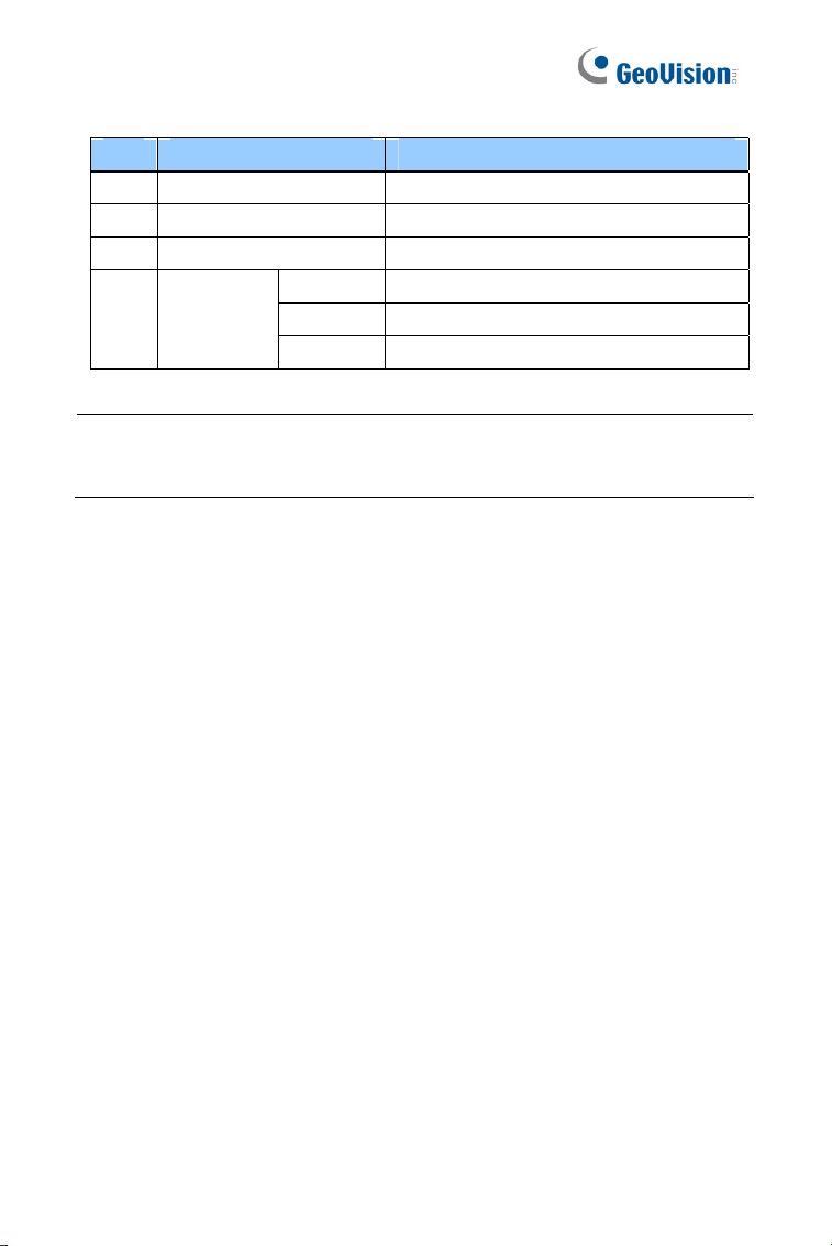
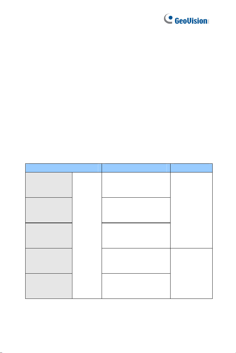
Options
Optional devices can expand your camera’s capabilities and versatility.
Contact your dealer for more information.
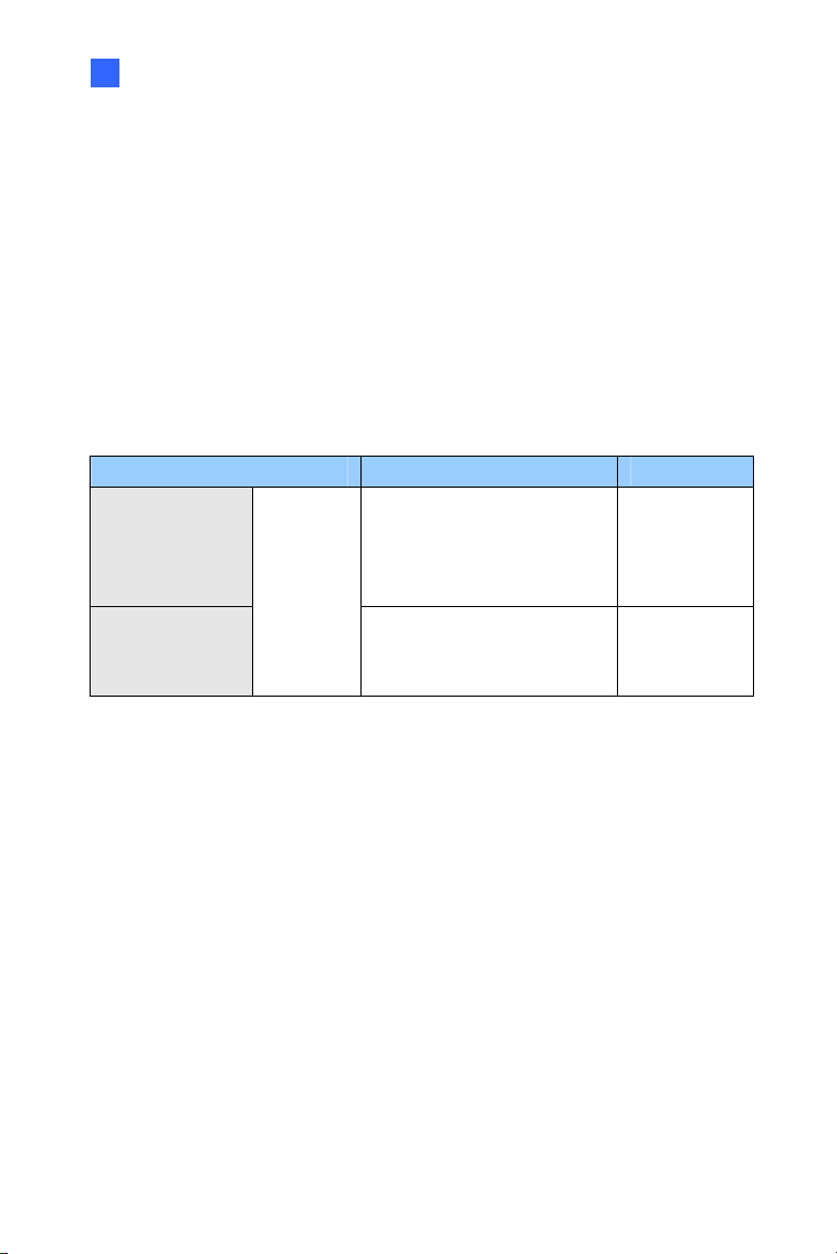
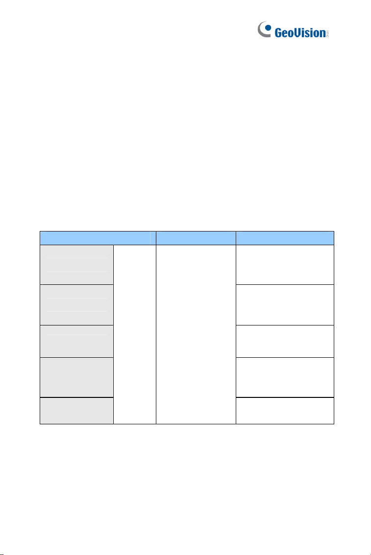
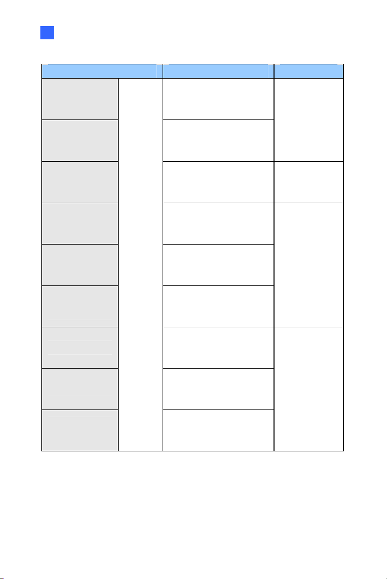
Device Description
I/O Cable
The I/O cable is a multi-connector providing I/O,
DC 12V power, and audio connectivity for the
camera.
Length: 106.8 cm (3.5 ft)
GV-Mount
Accessories
The GV-Mount Accessories provide a
comprehensive lineup of accessories for
installation on ceiling, wall corner and pole. For
details, see GV-Mount Accessories Installation
Guide.
GV-PA191 PoE
Adapter
The GV-PA191 PoE adapter is designed to
provide power and network connection to the
cameras over a single Ethernet cable.
GV-POE
The GV-POE is designed to provide power along
with network connection for IP devices. The GV-
POE is available in various models with different
numbers and types of ports.
Power Adapter
The power adapter is available for all Bullet
Camera, Ultra Bullet Camera (except GV-
BL2511-E / 5311-E), and Target Bullet Camera.
Contact our sales representatives for the
countries and areas supported.
GV-Relay V2
The GV-Relay V2 is designed to expand the
voltage load of GV IP devices. It provides 4 relay
outputs, and each can be set as normally open
(NO) or normally closed (NC) independently as
per your requirement.
vii
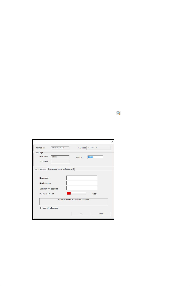
Creating GV-IP Camera’s Login
Credentials
The default Administrator and Guest accounts are no longer supported by
GV-IPCam H.265 series firmware V1.14 or later. When purchasing a new
camera or performing factory resetting, you need to set up a login
username and password for the camera.
1. Download and install GV-IP Device Utility from the company
website.
2.
On the GV-IP Device Utility window, click
to search for your GV-
IP camera.
3. Double-click your GV-IP camera in the GV-IP Device Utility list. This
dialog box appears.
4. Click the Change Username and Password tab to type a new
username and password. Note that the new password must meet
the password strength requirements.
5. Optionally click Upgrade all devices to use the same username
and password on all other devices.
viii
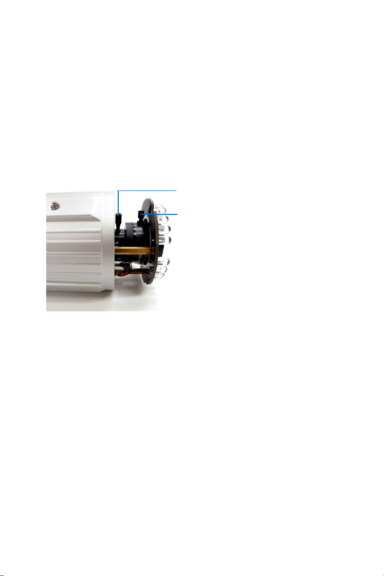
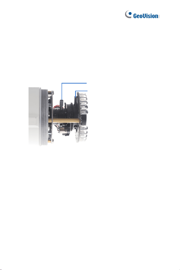
Note for Adjusting Focus and Zoom
When adjusting the Focus and Zoom Screws on Bullet Camera, do not
over tighten the Focus and Zoom screws. The screws only need to be as
tight as your finger can do it. It is not necessary to use any tools to get
them tighter. Doing so can damage the structure of lens.
For example,
Zoom Screw
Focus Screw
The maximum torque value for all the zoom and focus screws is 0.049 N.m
ix
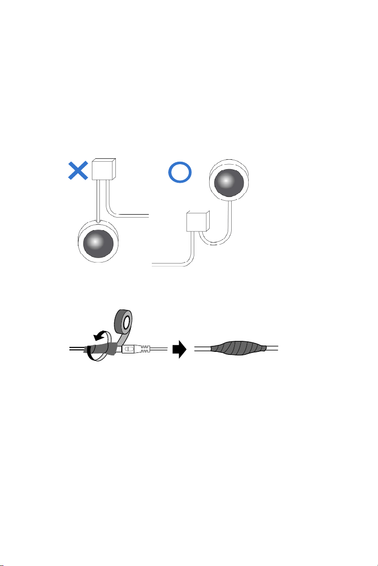
Note for Installing Camera Outdoor
When installing the cameras outdoor, be sure that:
1. The camera is set up above the junction box to prevent water from
entering the camera along the cables.
2. Any PoE, power, audio and I/O cables are waterproofed using
waterproof silicon rubber or the like.
x
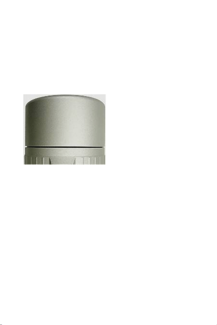
Note for Closing the Bullet Camera
Cover
To ensure that the camera performs its full capacity against water and dust,
tightly close and lock the camera cover as indicated below.
Note for Silica Gel Bags
1. The silica gel bag loses its effectiveness when the dry camera is
opened. To prevent the lens from fogging up, replace the silica gel
bag every time you open the camera, and conceal the gel bag in
camera within 2 minutes of exposing to open air.
2. When the camera is shipped, a silica gel bag will be included inside
the camera. For the first-time user, replace the silica gel bag prior to
the installation to avoid foggy live view.
xi
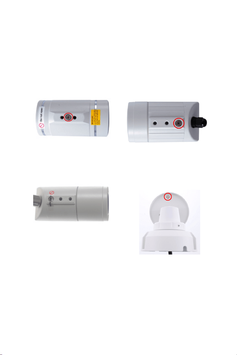
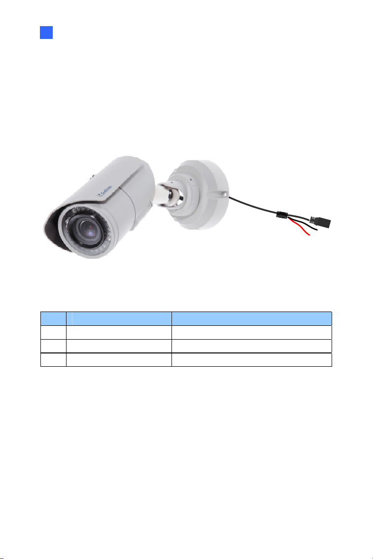
Note for Waterproofing Failures
To avoid waterproofing failures, do not open the screw on the camera body.
The screw on Ultra Bullet
Camera
The screw on Target Bullet
Camera
The screw on GV-EBL2101 /
2111 / 3101 / 5101
The screw on GV-BL3700 /
5700

1
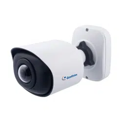
Chapter 1 Bullet Camera (Part I)
The Bullet Cameras are specifically designed for outdoors and are
weatherproof (IP66 or IP67). They are equipped with IR LEDs for infrared
illumination in night vision applications. The models described in this
chapter use auto iris, which allows for automatic control of exposure.
The WDR Pro models enhance the image by processing contrasting
intensity of light. The super low lux models can produce color live view in
near darkness. The motorized varifocal lens models allow the user to
adjust the focus and zoom through the Web interface.
2
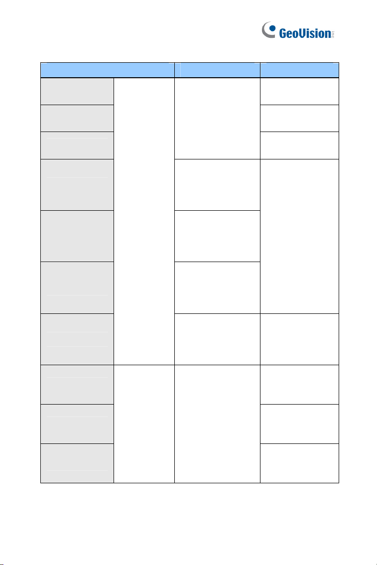
Model No. Specifications Description
GV-BL120D 1.3 MP, H.264, Low Lux
GV-BL130D 1.3 MP, H.264
GV-BL220D 2 MP, H.264
GV-BL320D 3 MP, H.264
GV-BL1500
1.3 MP, H.264, Super
Low Lux
GV-BL2400 2 MP, H.264, WDR Pro
GV-BL2500
2 MP, H.264, Super Low
Lux
GV-BL3400
Varifocal
lens
Auto Iris, f: 3 ~ 9
mm, F/1.2, 1/2.7’’
ø 14 mm Lens
Mount
3 MP, H.264, WDR Pro
GV-BL1210
1.3 MP, H.264, Low Lux,
3X Optical Zoom
GV-BL2410
2 MP, H.264, WDR Pro,
3X Optical Zoom
GV-BL3410
Auto Iris,
f: 3 ~ 9 mm,
F/1.2, 1/2.7’’
ø 14 mm Lens
Mount
3 MP, H.264, WDR Pro,
3X Optical Zoom
GV-BL5310
Motorized
varifocal
lens
Auto Iris,
f: 4.5 ~ 9 mm,
F/1.2, 1/2.7’’
ø 14 mm Lens
Mount
5 MP, H.264, 2X Optical
Zoom

Bullet Camera (Part I)
3
1
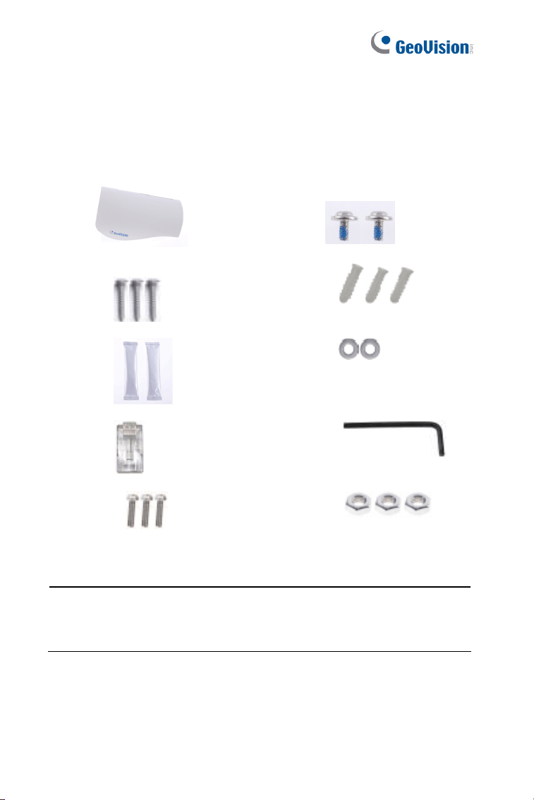
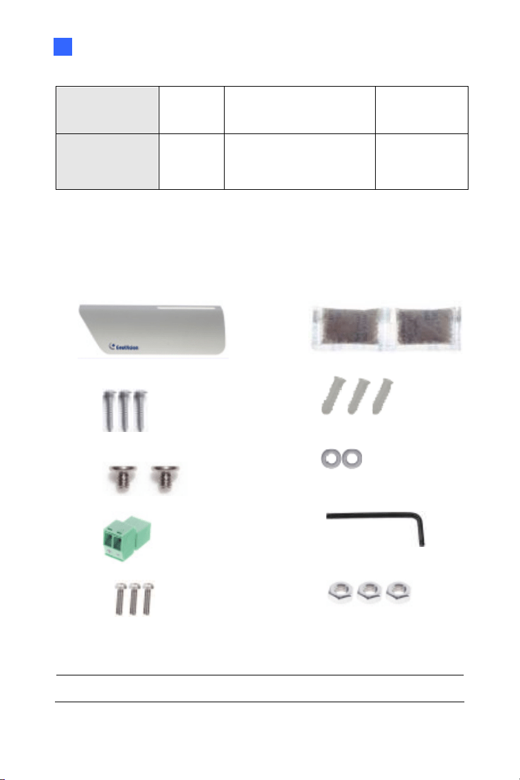
1.1 Packing List
Bullet Camera
Self Tapping Screw x 3
Plastic Screw Anchor x 3
Torx Wrench x 2
Sun-Shield Cover Kit (Sun-Shield Cover, Philips Head Screw x 2,
Plastic Screw Spacer x 2 and Hexagon Screw x 2)
Silica Gel Bag x 2
2-Pin Terminal Block
Power Adapter
Download Guide
Warranty Card
Note: The power adapter can be excluded upon request.
4
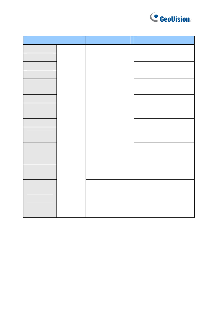
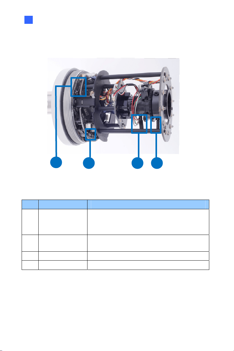
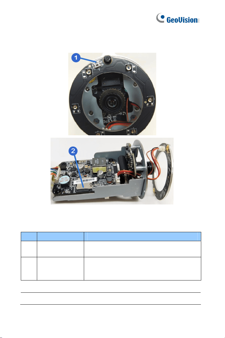
1.2 Overview
1
2 3 4
Figure 1-1
No. Name Description
1 Memory Card Slot
Receives a micro SD card (SD/SDHC,
version 2.0 only, Class 10).
2 Zoom Screw Holds the zoom lens in place.
3 Focus Screw Holds the focus lens in place
4 Default Button
Resets all configurations to factory default.
For details, see 1.4 Loading Factory Default.
Bullet Camera (Part I)
5
1
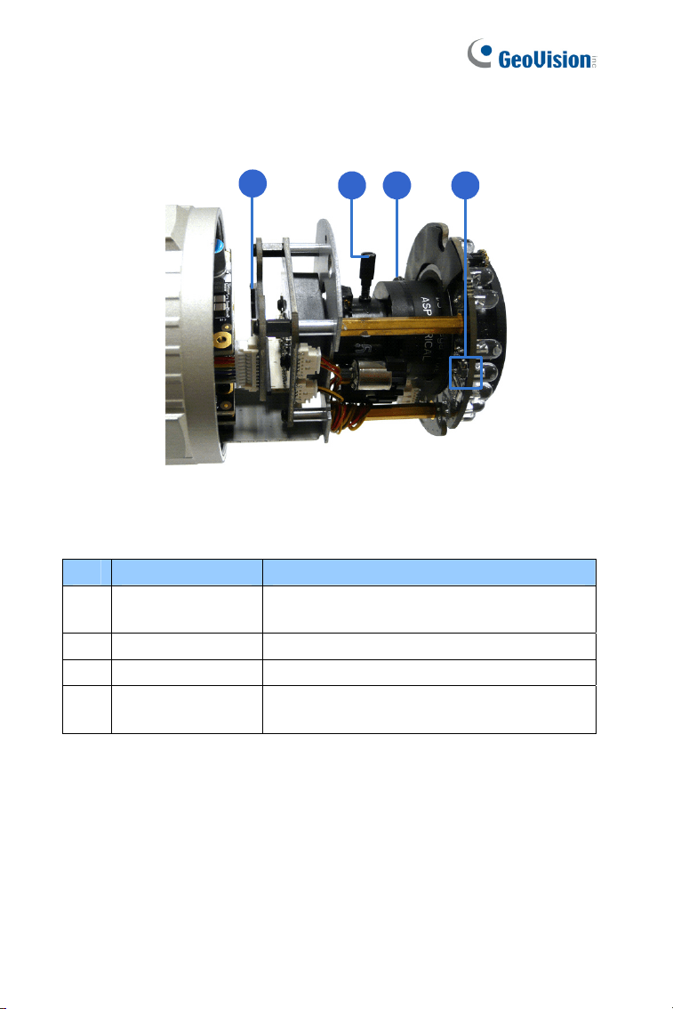
1.3 Installation
These instructions describe the basic installation of the Bullet Camera.
1. Slide the cable clamp to the camera base.
Cable Clamp
Figure 1-2
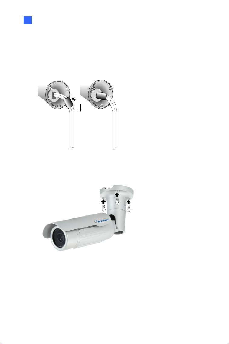
2. Install the Bullet Camera to the wall.
Figure 1-3
3. Remove the protection sticker from the camera’s cover.
4. Connect the power, network and other wires to the Bullet Camera.
See 1.3.1 Connecting the Camera.

6
5. Access the live view. For details, see 8.2 Accessing the Live View.
6. Adjust angles of the camera body based on the live view. Three
shafts can be adjusted. See 1.3.2 Adjusting the Angles.
7. Loosen the camera’s cover, adjust the focus of the camera and
optionally insert a micro SD card (SD/SDHC, version 2.0, Class 10)
into the SD card slot. See 1.3.3 Adjusting Lens and Inserting a
Memory Card.
8. Fasten the camera’s cover.
9. Install the sun-shield cover to the Bullet Camera. For details, see
1.3.4 Installing the Sun-Shield Cover.
Bullet Camera (Part I)
7
1
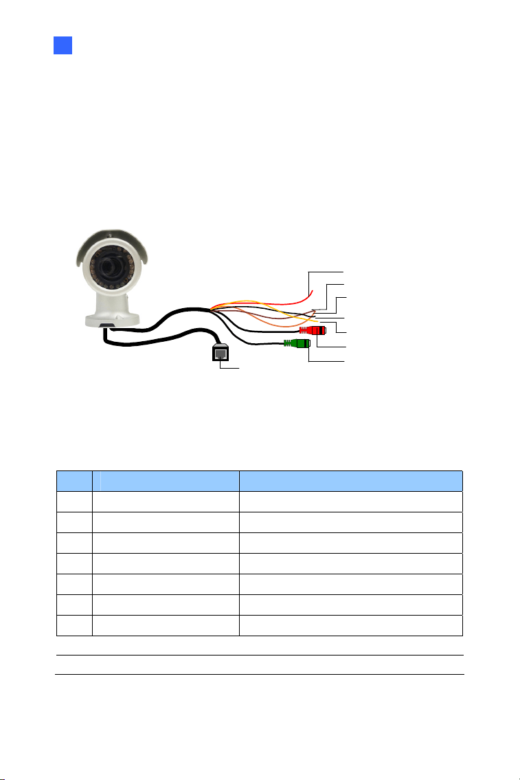
1.3.1 Connecting the Camera
Wire Definition for Auto Iris Models
The 7-Pin Data Cable provides connections for power, ground, 1 sensor
input, 1 alarm output, audio input and audio output. The wires are
illustrated and defined below:
Ethernet (PoE)
Digital In (Red)
DC 12V+ / AC 24V + (Brown)
Digital Out (Orange)
DC 12V- / AC 24V - (Black)
GND (Yellow)
Audio In (Red)
Audio Out (Green)
Figure 1-4
No. Wire Color Definition
1 Red Digital In
2 Brown DC 12V+ / AC 24V+
3 Orange Digital Out
4 Black DC 12V- / AC 24V-
5 Yellow Ground
6 Red RCA Audio in
7 Green RCA Audio out
Note: Audio In and Out connectors may also come as terminal blocks.
8
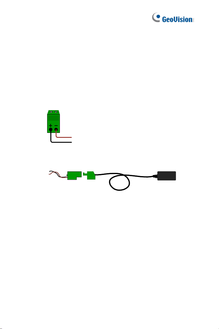
Power Connection
Use one of the following methods to supply power to the camera.
Use a Power over Ethernet (PoE) adapter to connect the camera to
the network, and the power will be provided at the same time.
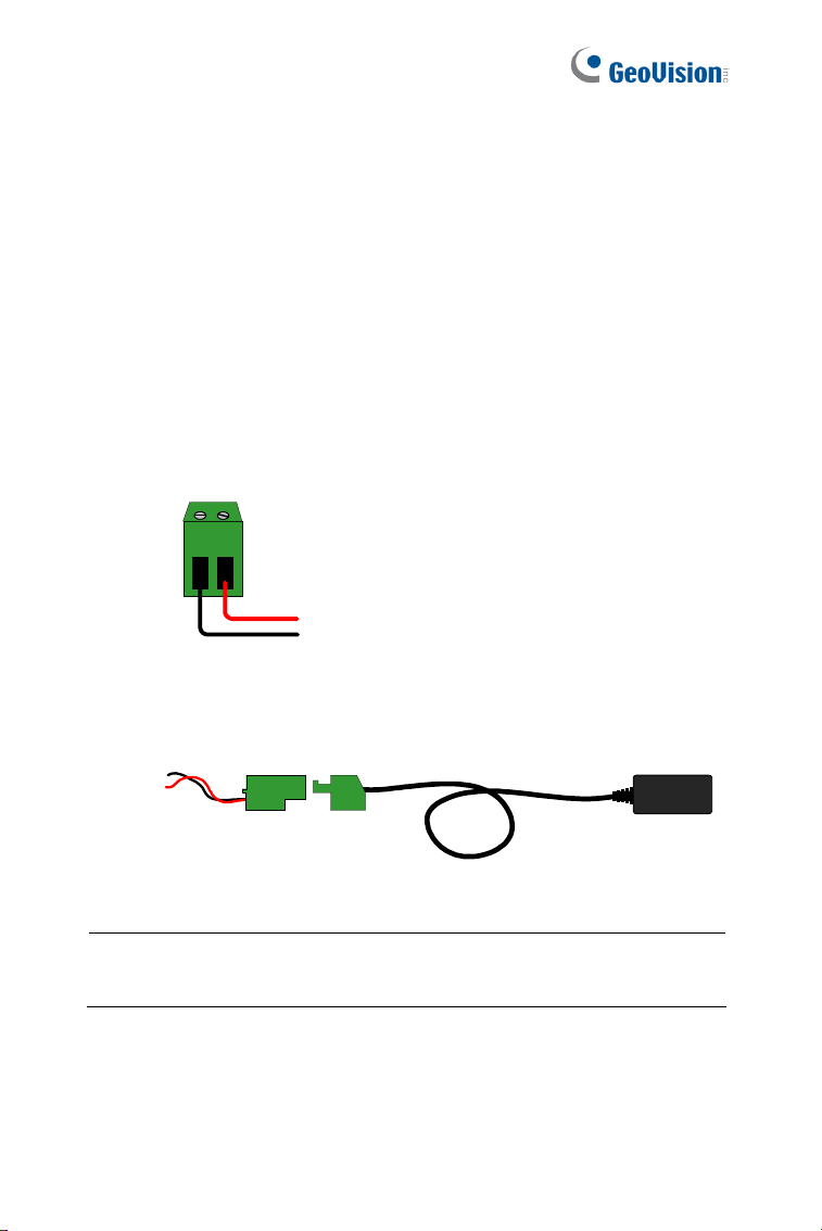
Plug the power adaptor to the terminal block as shown below.
Insert the black wire of the Bullet Camera to the left pin (+) and
the brown wire to the right pin (-).
Figure 1-5
Connect the DC 12V Power Adapter to the Terminal Block.
DC 12V Power Adaptor
Terminal Block
Figure 1-6
Bullet Camera (Part I)
9
1
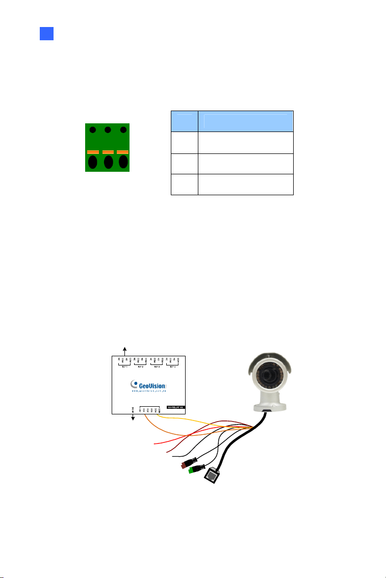
I/O Device Connection
The camera supports one digital input and one digital output of dry contact.
Pin Function
1 Digital Output
2 GND
I/O
1
2
3
Figure 1-7
3 Digital Input
For details on how to enable an installed I/O device, see 4.2 I/O Settings,
GV-IPCam Firmware Manual.
Voltage Load Expansion (Optional)
The camera can only drive a maximum load of 200mA 5V DC. To expand
the maximum voltage load to 10A 250V AC, 10A 125V AC or 5A 100V DC,
connect the camera to a GV-Relay V2 module (optional product). Refer to
the figure and table below.
Output Devices
Connect to Power
Figure 1-8
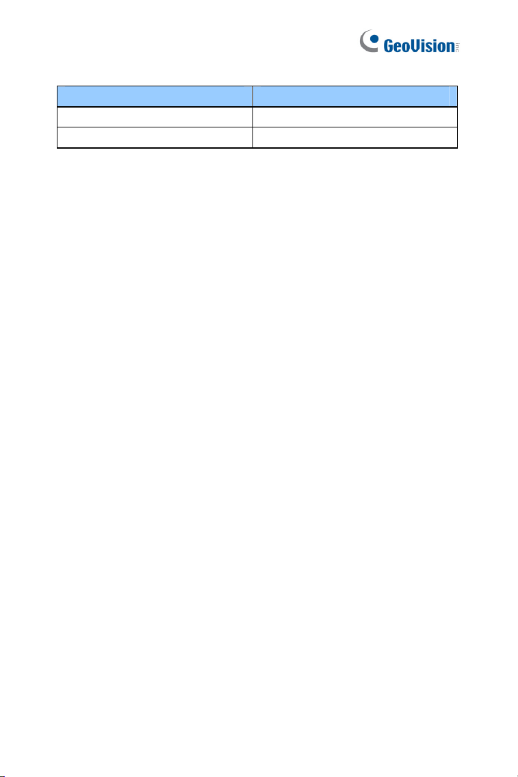
10
GV-Relay V2 Bullet Camera
COM Ground (Yellow)
DO1 Digital Out (Orange)
Bullet Camera (Part I)
11
1
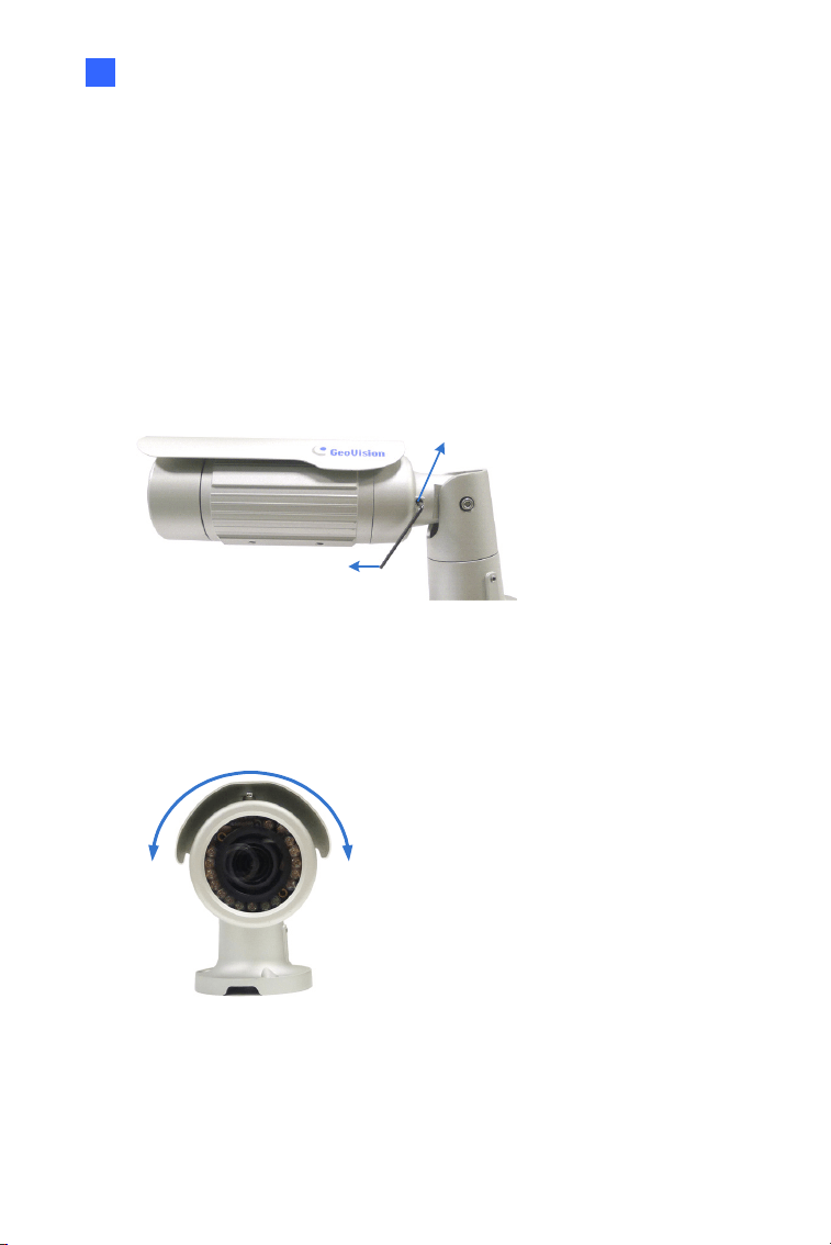
1.3.2 Adjusting the Angles
The Bullet Camera is designed to be adjustable in three shafts for easy
and flexible installation.
First Shaft
You can adjust the camera body by 360 degrees to the right or the left.
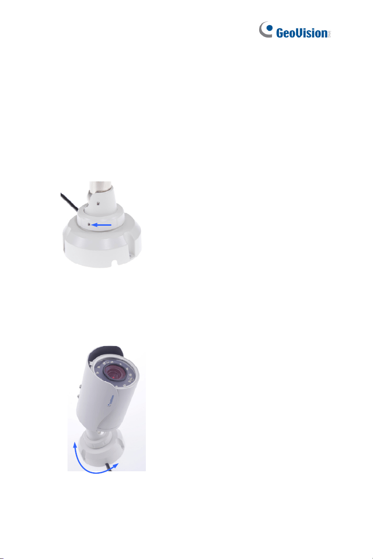
1. Unscrew the panning lock screw with the torx wrench.
Torx Wrench
Panning Lock Screw
Figure 1-9
2. Adjust the angle of camera body to the right or the left, and fasten
the panning lock screw.
0 ~ 360°
Figure 1-10
12
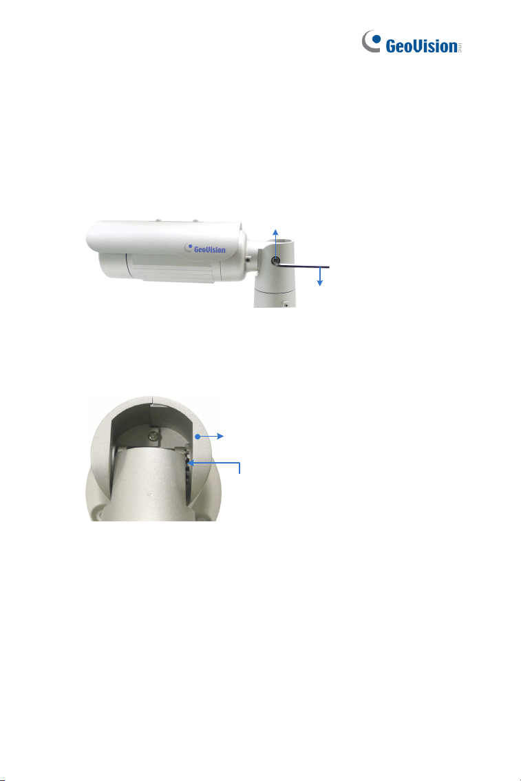
Second Shaft
You can adjust the camera body up and down by 90, 112.5, 135, 157.5 or
180 degrees by using the gears inside the camera body and the camera
base.
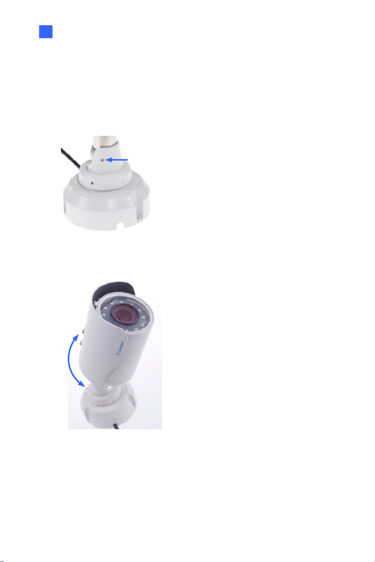
1. Unscrew the tilting lock screw with the torx wrench.
Torx Wrench
Tilting Lock Screw
Figure 1-11
2. Hold the camera body, and move the camera base to the right to
separate the camera gears.
Camera Body
Camera Gears
Move the Camera
Base to the Right
Figure 1-12
Bullet Camera (Part I)
13
1
3. Adjust the angle of camera body to 90°, 112.5°, 135°, 157.5° or 180°.
Then move the camera base to the left to combine the gears.
90°
112.5°
180 °
157.5°
135 °
Figure 1-13
4. Fasten the tilting lock screw.
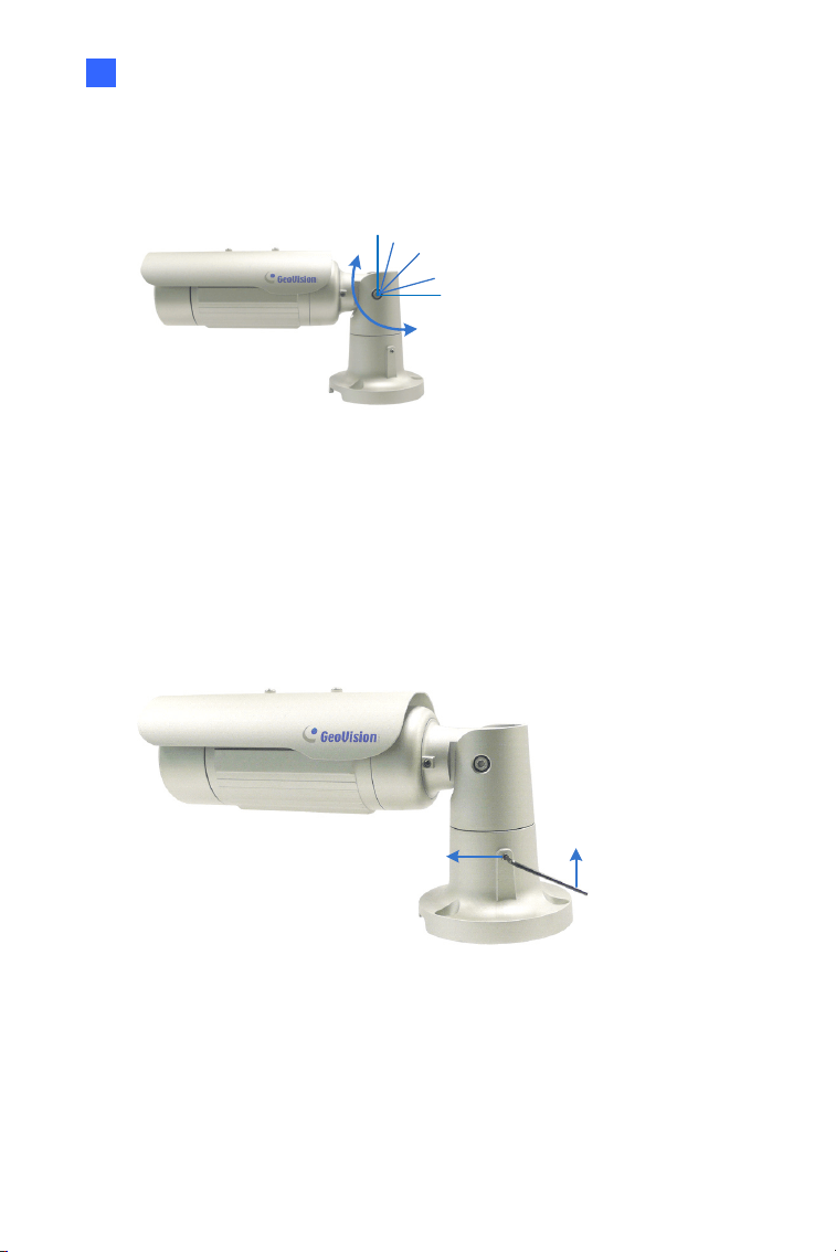
Third Shaft
You can adjust the camera base by 360°.
1. Unscrew the base fixing screw with the torx wrench.
Torx Wrench
Base Fixing Screw
Figure 1-14
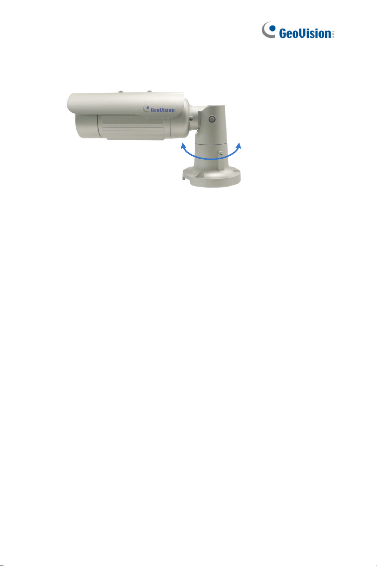
14
2. Adjust the angle of camera base, and fasten the base fixing screw.
0~360°
Figure 1-15
Bullet Camera (Part I)
15
1
1.3.3 Adjusting Lens and Inserting a Memory Card
To adjust the camera’s zoom and focus or to insert a micro SD card
(SD/SDHC, version 2.0 only, Class 10), follow the steps below.
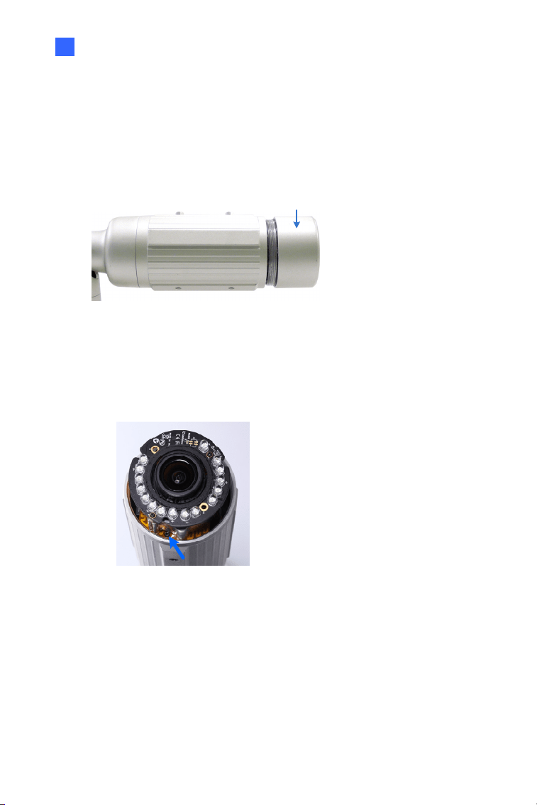
1. Loosen the camera’s cover.
Camera’s Cover
Figure 1-16
For GV-BL2511-E / 5311-E, loosen the camera’s cover and the screw
as indicated below.
Figure 1-17
16
2. To adjust for image clarity, follow the steps below.
For models with zoom and focus screws, pull out the camera
and remove the silica gel bag to access its focus and zoom
screws. Use GV-IP Device Utility to help you. For details, see 8.3
Adjusting Image Clarity.
Silica Gel Bag
Zoom Screw
Focus Screw
Figure 1-18
For motorized varifocal lens models, adjust for image clarity
through the Web interface. For details, see Zoom, Focus Change,
and Focus Mode settings in 3.2.2 The Control Panel of the Live
View Window, GV-IPCam Firmware Manual.
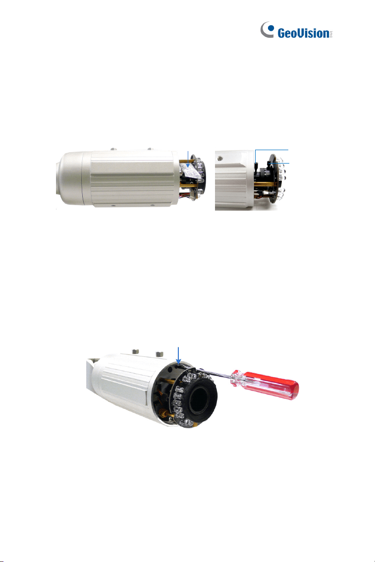
3. To insert a micro SD card, follow the steps below.
4. Loosen the fixing screw.
Fixing Screw
Figure 1-19
5. Slightly pull out the camera module.
Bullet Camera (Part I)
17
1
6. Insert a micro SD card into the memory card slot.
Memory Card Slot
Figure 1-20
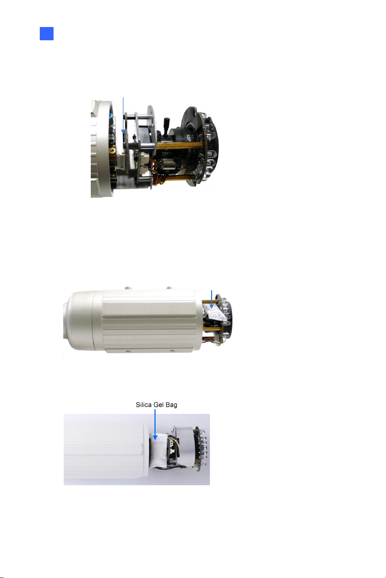
7. Push the camera back and fasten the fixing screw.
8. Insert a new silica gel bag to the camera module and fasten the
camera’s cover.
Silica Gel Bag
Figure 1-21
Figure 1-22 (GV-BL2511-E/5311-E)
18
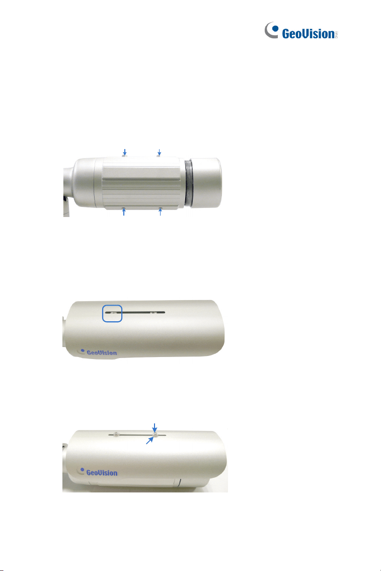
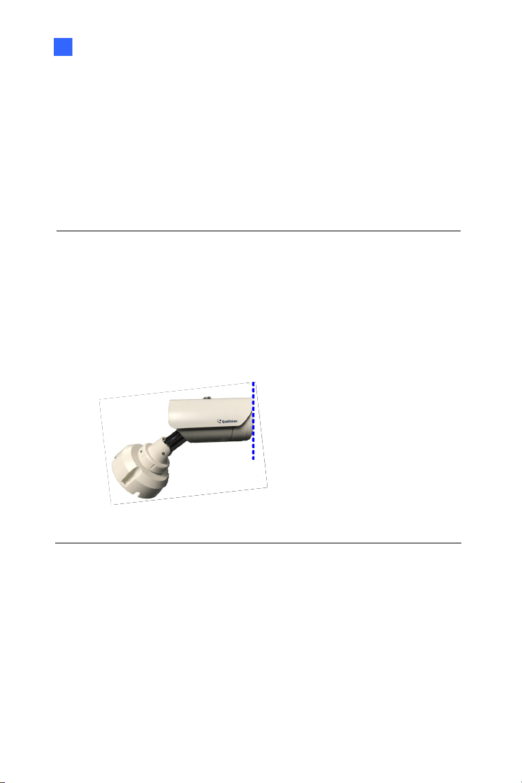
1.3.4 Installing the Sun-Shield Cover
After setting up the Bullet Camera, now you can install the sun-shield cover
to the camera.
1. Fasten the hexagon screws either on top or below the camera.
Hexagon Screws
Figure 1-23
2. Put the sun-shield cover on top of hexagon screws. Make sure to
aim the rear hexagon screw at the edge of the sun-shield cover’s
aperture for optimal sun-shield performance.
Sun-Shield Cover
Figure 1-24
3. Fasten the Philips head screws with the plastic screw spacers.
Philips Head Screw
Plastic Screw Spacer
Figure 1-25
Bullet Camera (Part I)
19
1
1.4 Loading Factory Default
You can restore factory default settings through the Web interface or
directly on the camera.
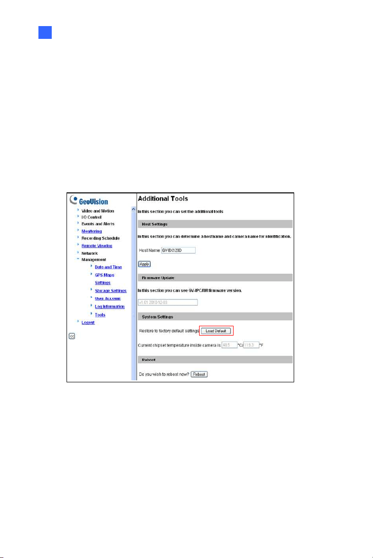
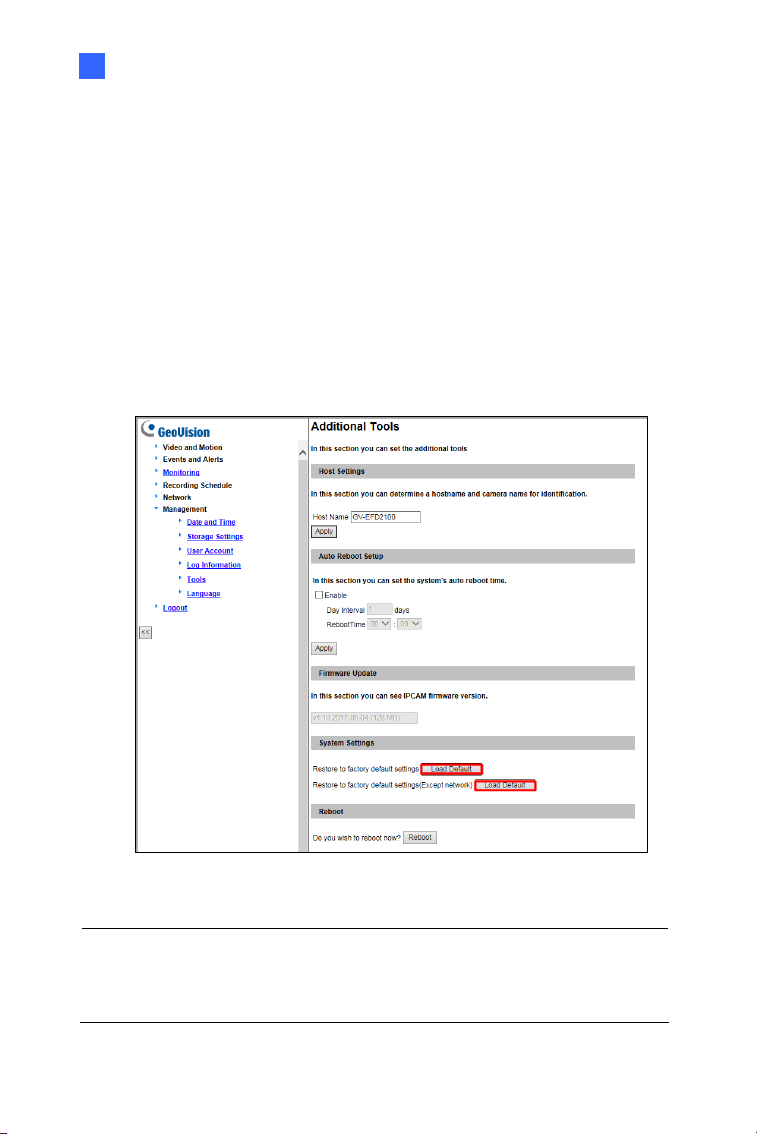
1.4.1 Using the Web Interface
1. On the left menu of Web interface, select Management and select
Tools. The Additional Tools dialog box appears.
2. Click the Load Default button in the System Settings section.
Figure 1-26
20
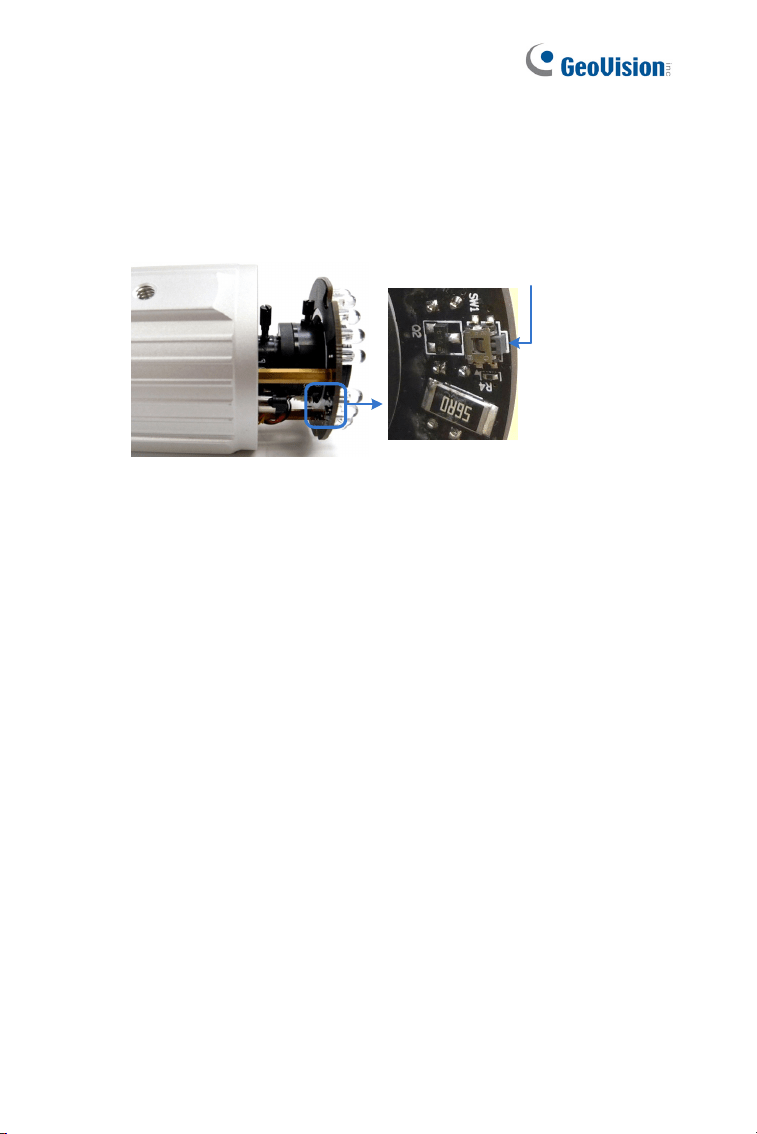
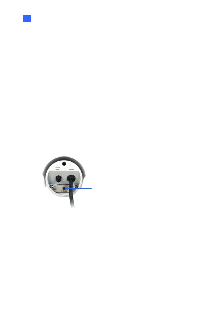
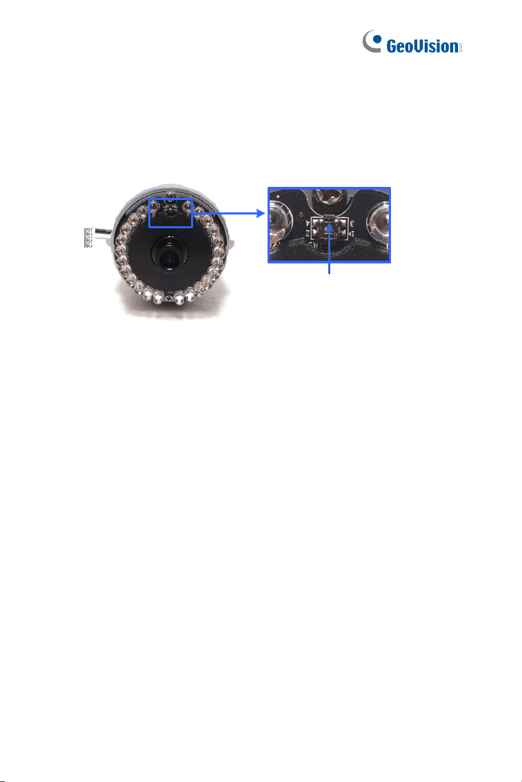
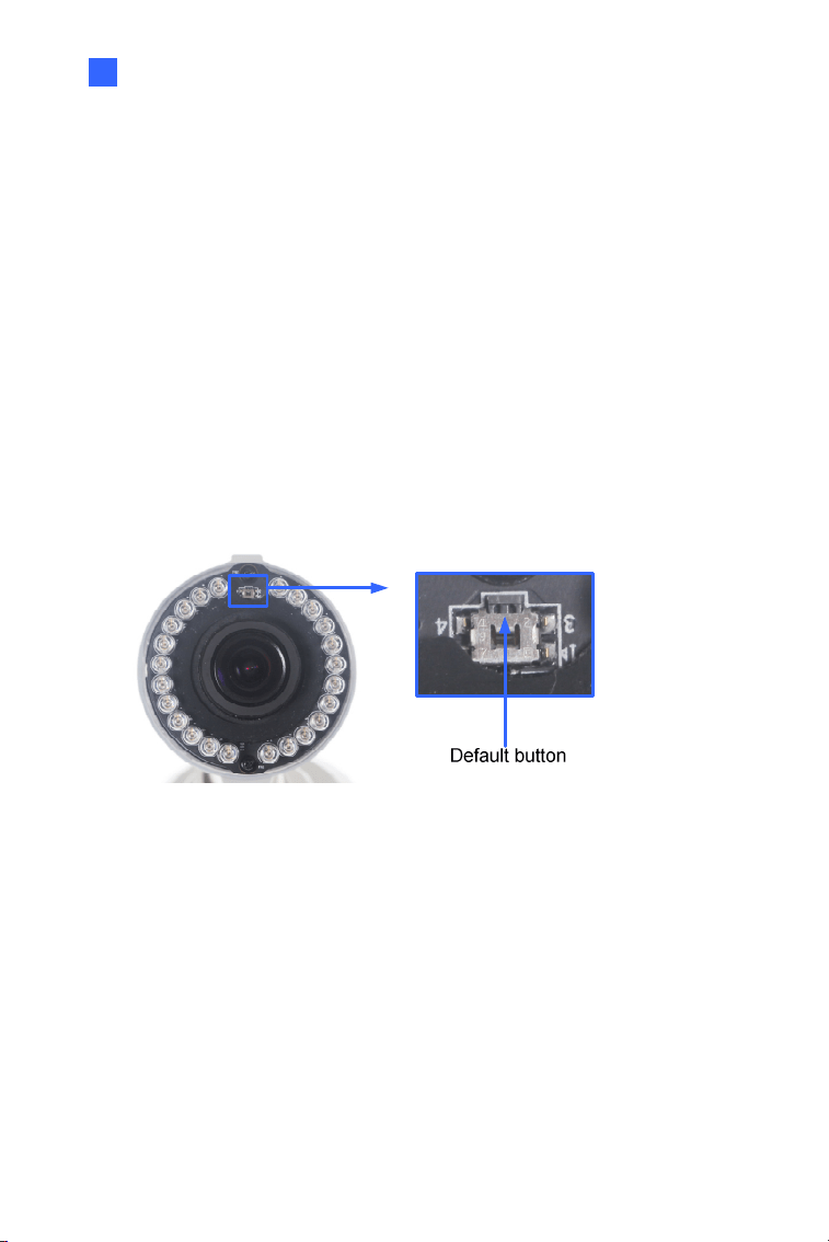
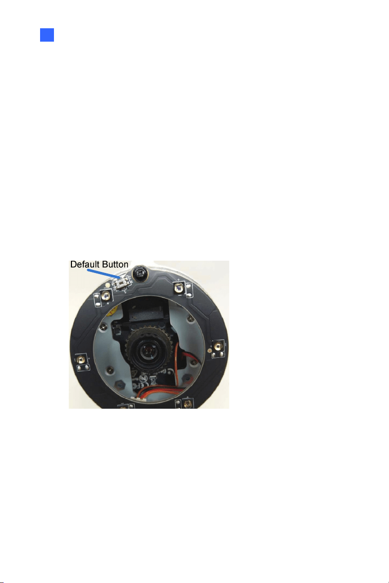
1.4.2 Directly on the Camera
1. Keep the power and network cables connected to the camera.
2. Loosen the camera’s cover.
3. Press and hold the default button for 8 seconds.
Default Button
Figure 1-27
4. Release the default button. When the process of loading default
settings is completed, the camera reboots automatically.
5. Replace the Silica Gel Bag and fasten the camera’s cover
immediately.

Bullet Camera (Part II)
21
2
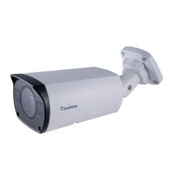
Chapter 2 Bullet Camera (Part II)
The Bullet Cameras are specifically designed for outdoors. They are
weatherproof (IP67) and equipped with IR LEDs for infrared illumination in
night vision applications. The models described in this chapter use P-Iris,
which allows for precise control of exposure, producing images with better
clarity and contrast.
The WDR Pro models enhance the image by processing contrasting
intensity of light. The super low lux models can produce color live view in
near darkness. The motorized varifocal lens models allow the user to
adjust the focus and zoom through the Web interface. The arctic models
can withstand extreme temperatures (-40°C ~ 50°C / -40°F ~ 122°F).
22
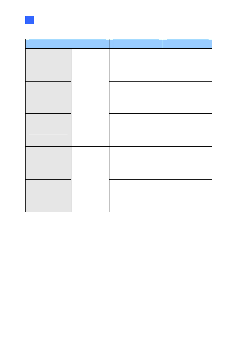
Model No. Specifications Description
GV-BL1501
1.3 MP, H.264,
Super Low Lux
GV-BL2501
2 MP, H.264,
Super Low Lux
GV-BL3401
P-Iris, f: 3 ~ 9 mm,
F/1.2, 1/2.7’’
ø 14 mm Lens
Mount
3 MP, H.264,
WDR Pro
GV-BL2702-3V
P-Iris, f: 2.8 ~ 12
mm, F/1.7, 1/2.7”,
ø 14 mm Lens
Mount
GV-BL2702-4V
P-Iris, f: 6 ~ 50
mm, F/1.6, 1/2.7”,
ø 14 mm Lens
Mount
GV-BL2702-5V
P-Iris, f: 9 ~ 22
mm, F/2.0, 1/2.7”,
ø 14 mm Lens
Mount
2 MP, H.265,
Super Low Lux,
WDR Pro
GV-BL4702
Varifocal
lens
P-Iris, f: 2.8 ~ 12
mm, F/1.7, 1/2.7”,
ø 14 mm Lens
Mount
4 MP, H.265,
Super Low Lux,
WDR Pro
GV-BL1511
1.3 MP, H.264,
Super Low Lux,
3X Optical Zoom
GV-BL2511
2 MP, H.264,
Super Low Lux,
3X Optical Zoom
GV-BL3411
Motorized
varifocal
lens
P-Iris, f: 3 ~ 9 mm,
F/1.2, 1/2.7’’
ø 14 mm Lens
Mount
3 MP, H.264,
WDR Pro, 3X
Optical Zoom
Bullet Camera (Part II)
23
2
Model No. Specifications Description
GV-BL5311
P-Iris, f: 4.5 ~ 9
mm, F/1.2, 1/2.7’’
ø 14 mm Lens
Mount
5 MP, H.264, 2X
Optical Zoom
GV-BL4713
P-Iris, f: 2.8 ~ 12
mm, F/1.7, 1/2.7”,
ø 14 mm Lens
Mount
4 MP, H.265,
Super Low Lux,
WDR Pro
GV-BL5713
Motorized
varifocal lens
P-Iris, f: 4 ~ 8 mm,
F/1.63, 1/1.8”,
ø 14 mm Lens
Mount
5 MP, H.265,
Low Lux, WDR
GV-BL2511-E
P-Iris, f: 3 ~ 9 mm,
F/1.2, 1/2.7’’
ø 14 mm Lens
Mount
2 MP, H.264,
Super Low Lux,
3X Optical Zoom
GV-BL5311-E
Motorized
varifocal
lens,
Extreme
temperature
tolerance
P-Iris, f: 4.5 ~ 9
mm, F/1.2, 1/2.7’’
ø 14 mm Lens
Mount
5 MP, H.264, 2X
Optical Zoom

24
2.1 Packing List
For GV-BL1501 / 2501 / 3401 / 1511 / 2511 / 3411 / 5311 / 2511-E /
5311-E, refer to the following packing list:
Bullet Camera
Self Tapping Screw x 3
Plastic Screw Anchor x 3
Torx Wrench x 3
Sun-Shield Cover Kit (Sun-Shield Cover, Philips Head Screw x 2,
Plastic Screw Spacer x 2, and Hexagon Screw x 2)
Silica Gel Bag x 2
2-Pin Terminal Block
3-Pin Terminal Block
Power Adapter
Installation Sticker
Ruler
Stand Kit (Conduit Converter, PG21 Conduit Connector, RJ-45
Connector, M3 Screw x 2, Cable Tie)
Mounting Kit (M4 Screw x 3, Nut x 3, Plate x 3)
Download Guide
Warranty Card
Note:
1. The power adapter can be excluded upon request.
2. The Mounting Kit is used for wall corner and pole installations using
GV-Mount300 / 310 / 400 / 410 (optional). For details, see GV-Mount
Accessories Installation Guide.

Bullet Camera (Part II)
25
2
For GV-BL2702 / 4702 / 4713 / 5713, refer to the following packing list:
H.265 Bullet Camera
Stand Kit (Conduit Converter, PG21 Conduit Connector, RJ-45
Connector, M3 Screw x 2, Cable Tie)
Sun-Shield Cover Kit (Sun-Shield Cover, Philips Head Screws x 2,
Plastic Screw Spacers x 2, Hexagon Screws x 2)
Mounting Kit (M4 Screw x 3, Nut x 3, Plate x 3)
Screw Anchor x 3
Screw for Mounting Kit x 3
Hex Wrench
4 mm Wrench
2.5 mm Wrench
Silica Gel Bag x 2
Ruler
Installation Sticker
Download Guide
Warranty Card
Note:
1. GV-BL4713 / 5713 does not include the Sun-Shield Cover Kit in the
packing list since the sun-shield cover is installed to the camera
upon delivery.
2. The Mounting Kit is used for wall corner and pole installations using
GV-Mount300 / 310 / 400 / 410 (optional). For details, see GV-
Mount Accessories Installation Guide.
26
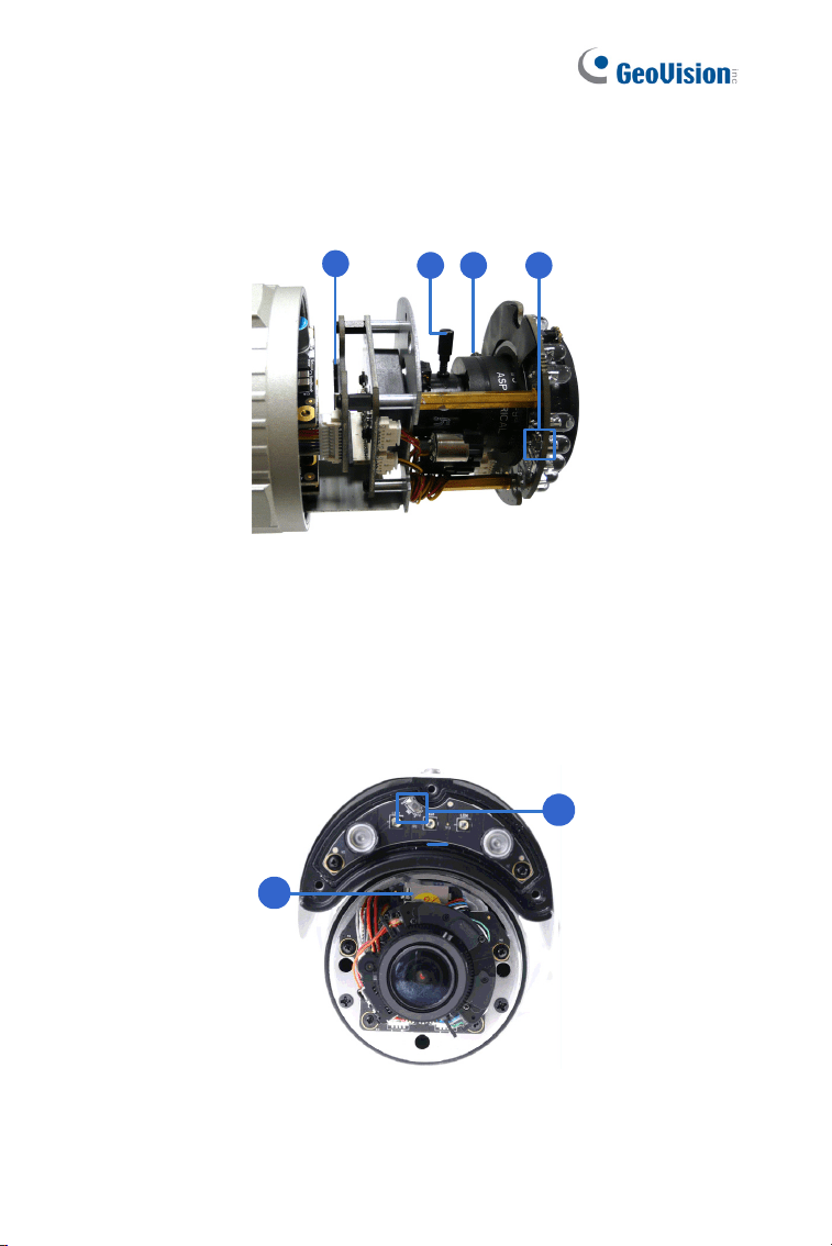
2.2 Overview
Twist off the camera cover to access the following:
1
2 3 4
Figure 2-1
GV-BL4713 / 5713
For GV-BL4713 / 5713, twist off the camera cover and loosen the three
screws on the front lid of the sun-shield cover to access the following:
1
4
Figure 2-2
Bullet Camera (Part II)
27
2
No. Name Description
1 Memory Card Slot
Receives a micro SD card (SD/SDHC,
version 2.0 only, Class 10).
2 Zoom Screw Holds the zoom lens in place.
3 Focus Screw Holds the focus lens in place
4 Default Button
Resets all configurations to factory default.
For details, see 1.4 Loading Factory Default.
Note:
1. The memory card slot of GV-BL2702 / 4702 / 4713 / 5713 supports
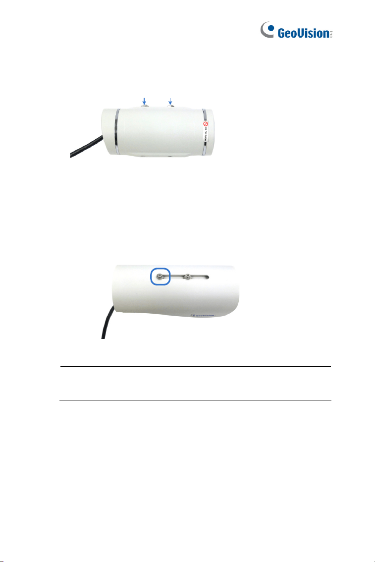
micro SD card (SD/SDHC/SDXC/UHS-I, Class 10).
2. To insert an SD card into GV-BL4713 / 5713, loosen the screw
indicated in the following left picture, and then open the sun-shield
cover to access the SD card slot.
Figure 2-3
28
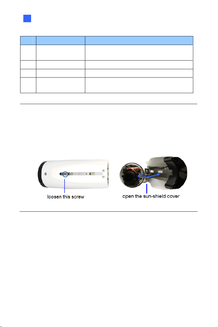
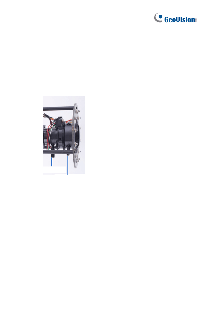
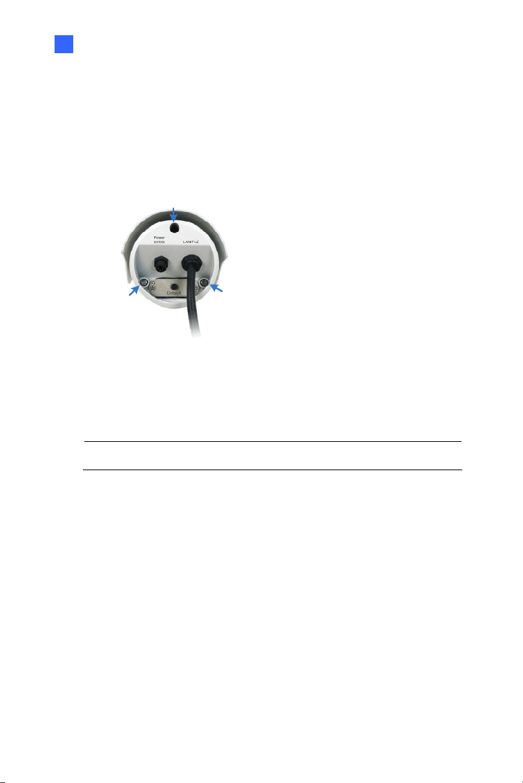
To access the following interface, remove the camera base using the
supplied torx wrench.
1
2 3 4 5
Figure 2-4
No. Name Description
1 LAN / PoE Connects to a 10/100 Ethernet or PoE.
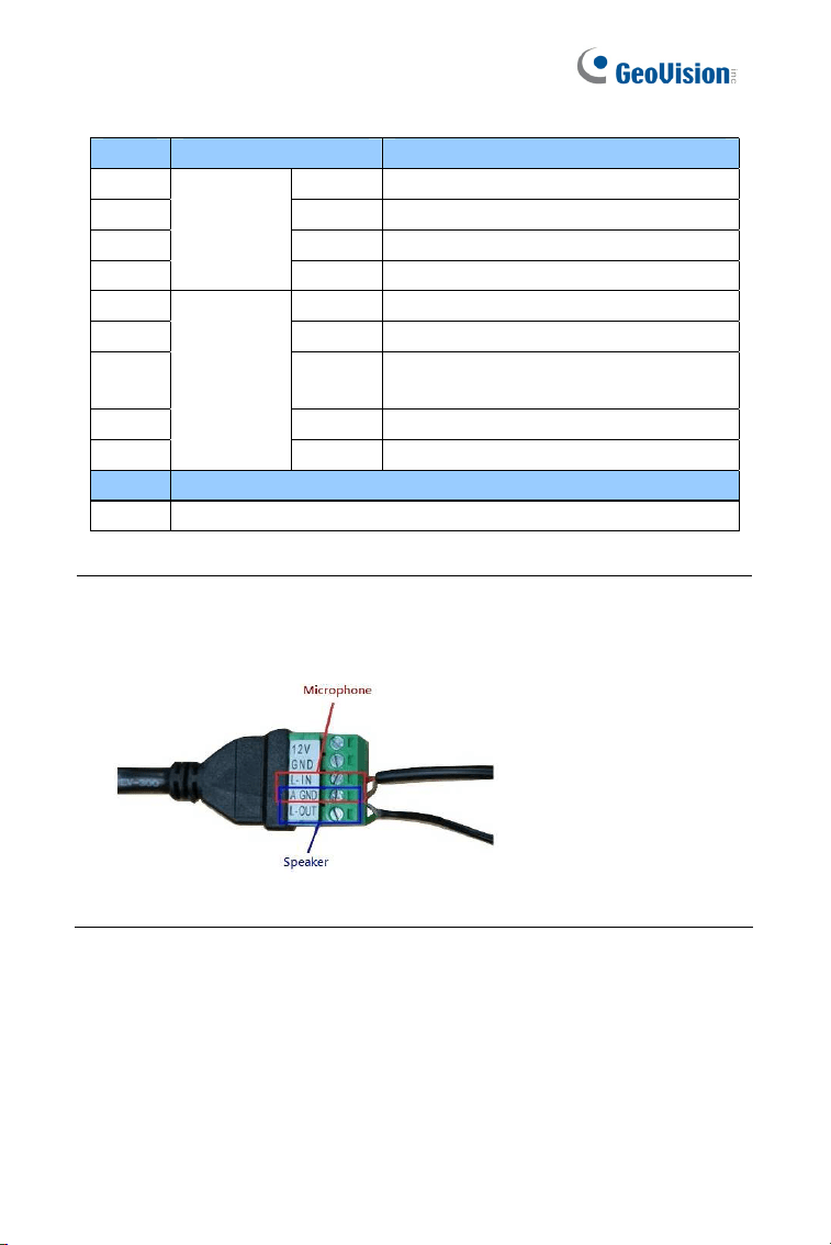
2 Audio In Connects a microphone for audio input.
3 Audio Out Connects a speaker for audio output.
4 I/O Terminal Block
Connects to I/O devices. For details, see
I/O Terminal, 2.4 Connecting the Camera.
5 DC 12V Port Connects to power.
Bullet Camera (Part II)
29
2
2.3 Installation
Follow the steps below to install the Bullet Camera.
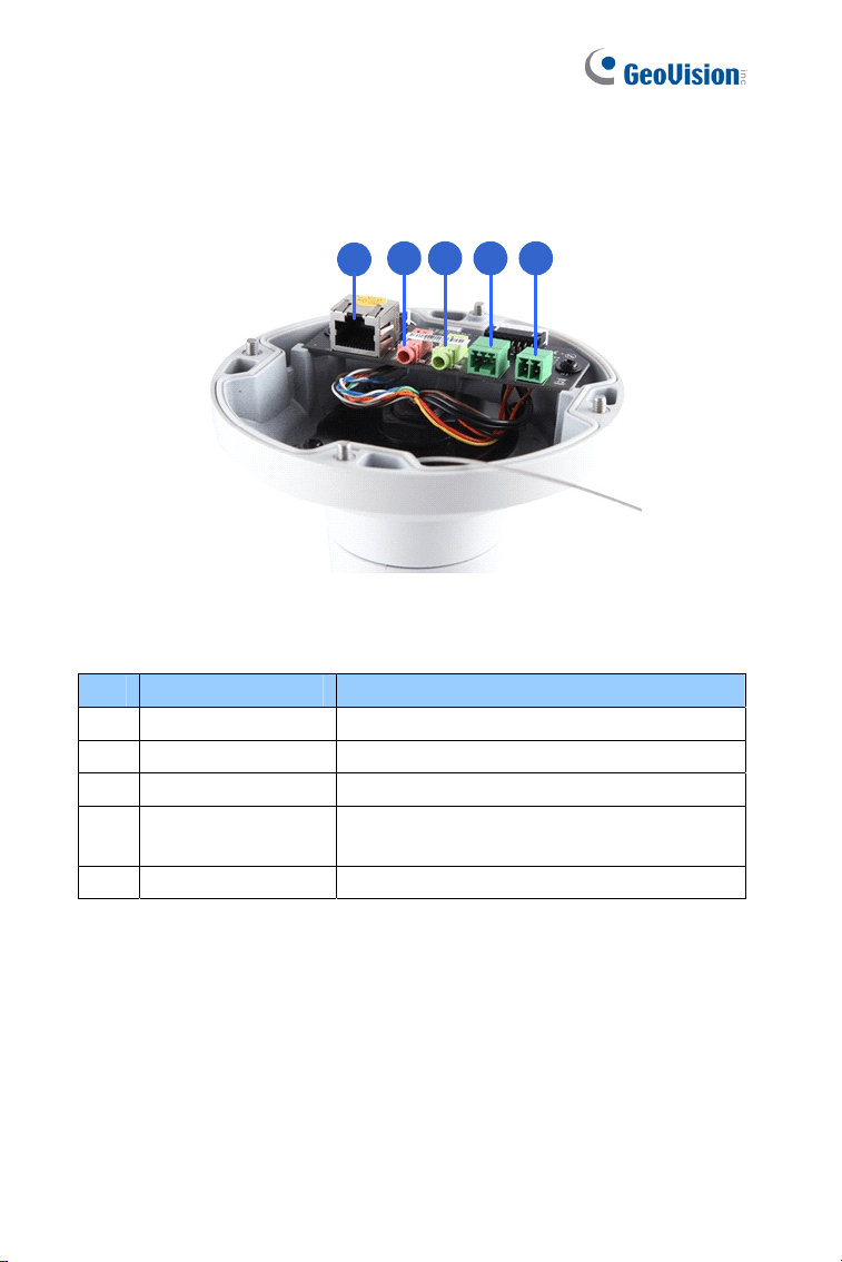
1. Paste the supplied sticker to the ceiling/wall. For wall installations,
make sure the arrow on the sticker points toward the ceiling.
Mount template
Figure 2-5
2. Drill the shaded area, and insert the screw anchor into the three
holes.
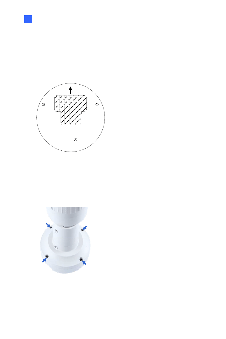
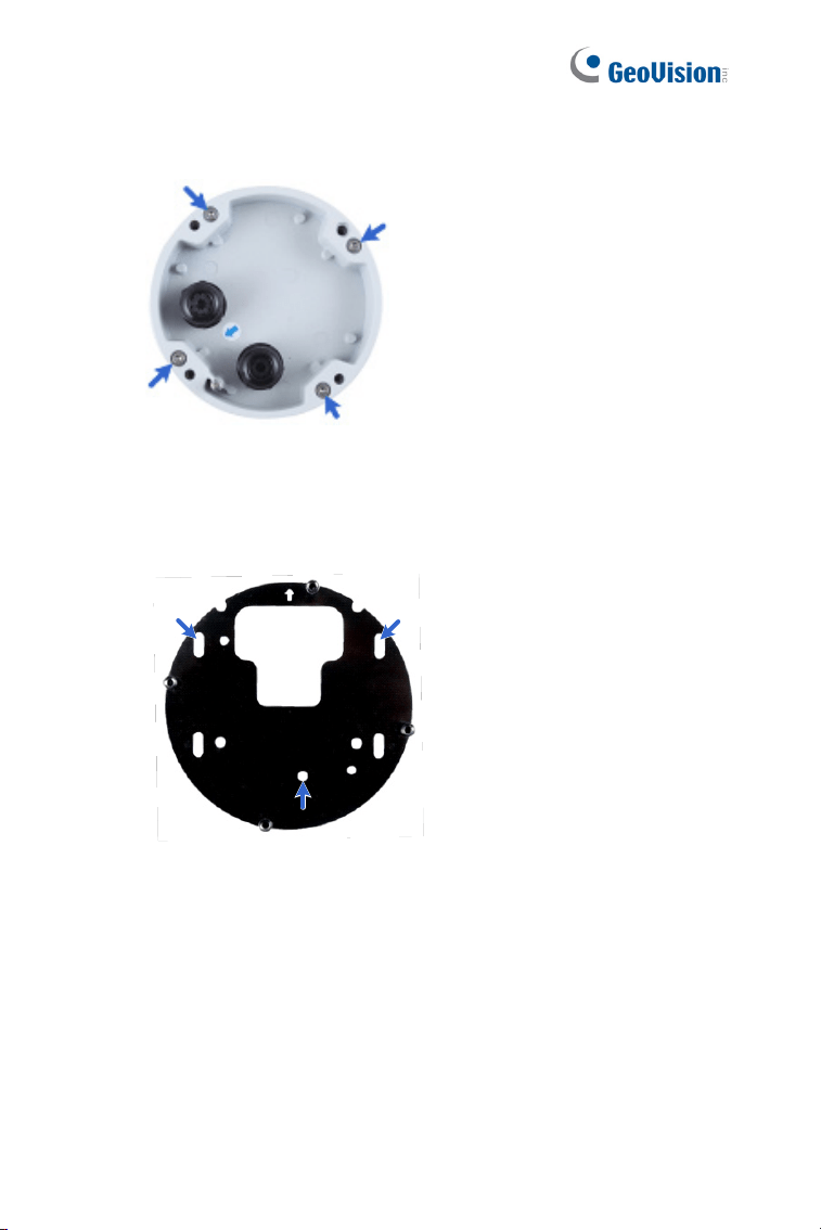
3. Loosen the indicated screws with the supplied torx wrench to
remove the base.
Figure 2-6
30
4. Loosen the indicated screws and remove the back plate.
Figure 2-7
5. Align and secure the back plate to the wall/ceiling with the supplied
self-tapping screws.
Figure 2-8
Bullet Camera (Part II)
31
2
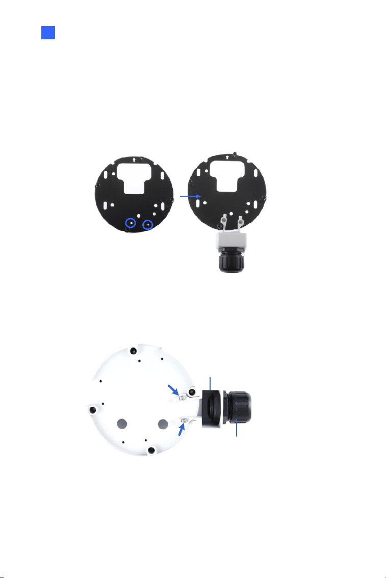
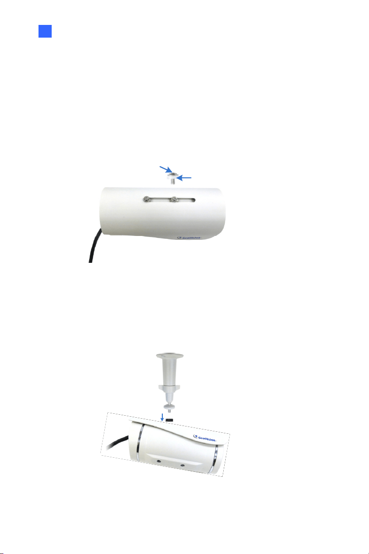
6. To optionally install a pipe, use one of the two methods illustrated
below depending on the type of the back plate that comes with your
camera:
A. If your plate comes with two knobs (as in Figure 2-9) Install the
supplied conduit converter to the back plate.
Figure 2-9
B. If your plate comes without knobs, install the conduit converter to
the camera.
Conduit Converter
PG21 Conduit Connector
Figure 2-10
32
7. Install the Ethernet cable.
A. Twist off and remove the cable seal and the conduit connector.
Cable Seal
Conduit Connector
Figure 2-11
B. Thread an Ethernet cable (with no RJ-45 connector on one end)
from the back panel through the cable seal and then through the
conduit converter (optionally installed at Step 6A).
Figure 2-12
IMPORTANT: Use the supplied ruler and leave about 10 cm of the
Ethernet cable between the connector and the cable seal.
Bullet Camera (Part II)
33
2
C. Re-install the cable seal. Make sure it is installed tightly to
waterproof the camera.
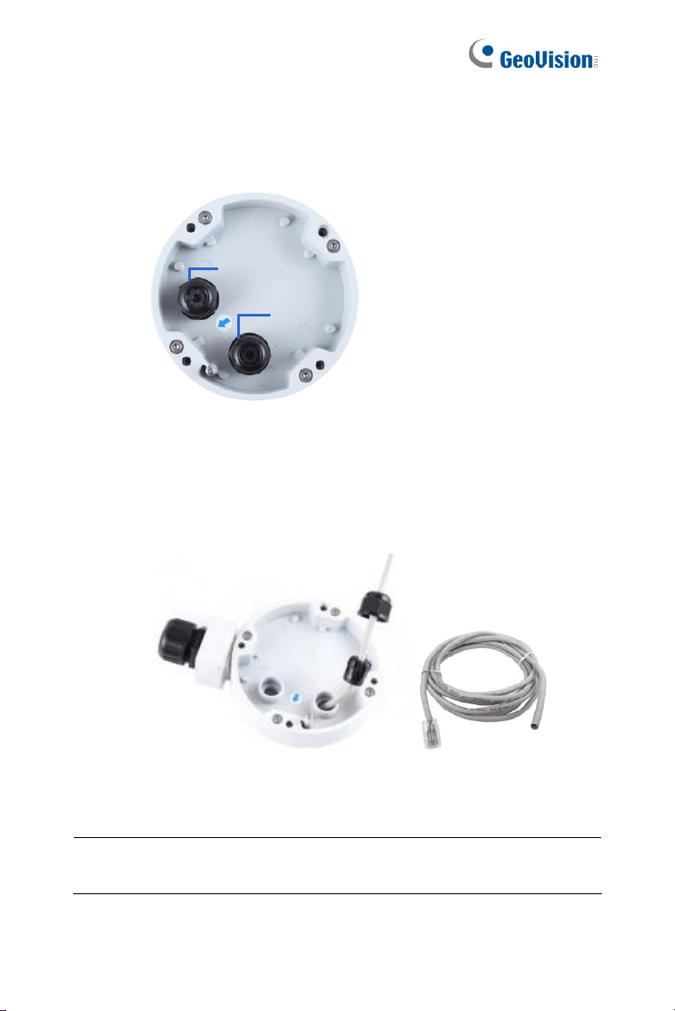
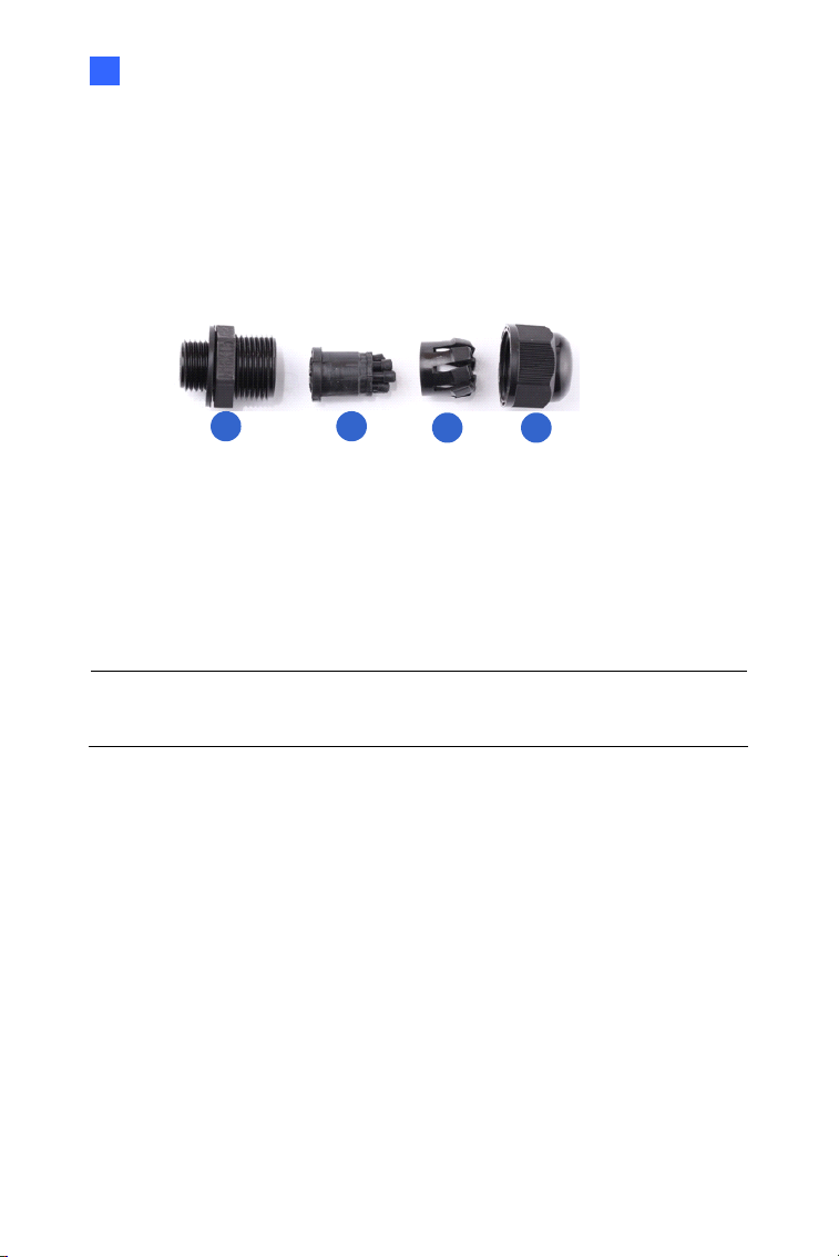
8. Thread wires into the camera.
A. Disintegrate the removed conduit connector. You should have 4
parts:
1 2
3 4
Figure 2-13
B. Remove the terminal block from the supplied power adapter.
C. Optionally thread audio wires, adapter wires, and I/O wires
through the conduit converter and then through part 1, 2, 3, and
4 of the conduit connector.
Tip: To make the threading easier, it is advised to thread the wires in the
order described here.
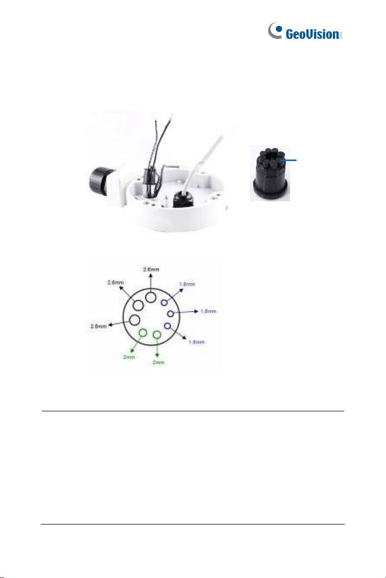
34
For part 2, there are 8 holes each labeled with its diameter.
Remove the plugs and push the wires to the corresponding hole
listed below:
Plug
Figure 2-14
2.6 mm: Audio
2 mm: DC12V / AC24V
1.8 mm: DIDO
Figure 2-15
IMPORTANT:
Use the supplied ruler and leave about 10 cm of audio, power, and
I/O wires between their connectors and the cable seal.
The plugs are used to prevent water from entering the camera
housing. Keep the unused holes plugged and save the removed
plugs for future use.
Only thread the wires through their designated holes on the conduit
connector to make sure the wires are properly sealed.
Bullet Camera (Part II)
35
2
9. Install the base to the back plate on the wall.
10. Connect the wires to the camera.
A. Install the terminal blocks to the power adapter and I/O devices.
See Power Connection and I/O Device Connections in 2.4
Connecting the Camera.
B. Install the supplied RJ-45 connector to the Ethernet cable.
C. Plug all the connectors to the camera panel.
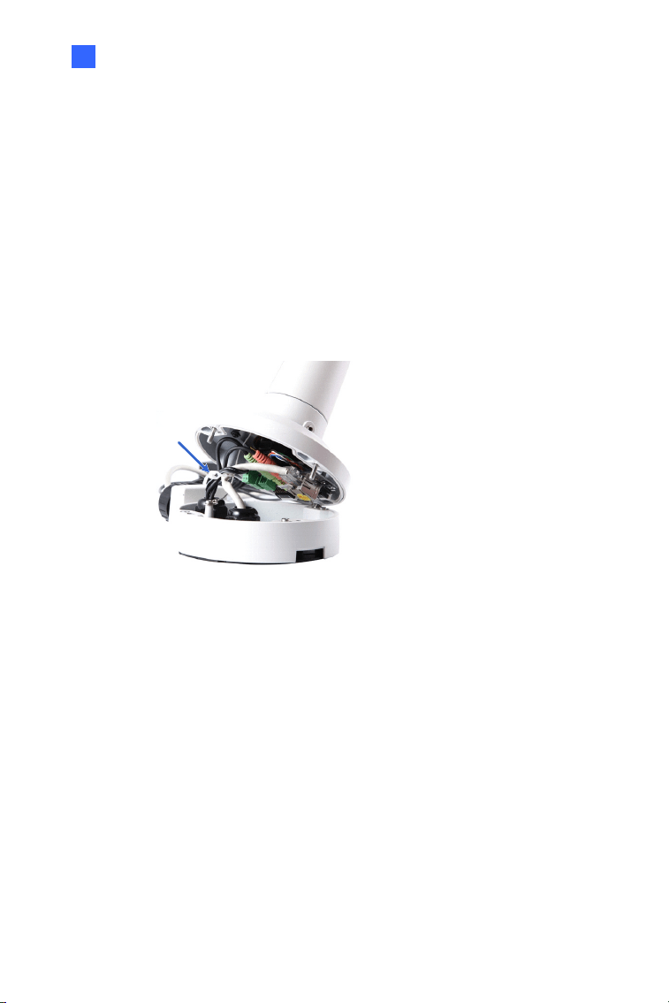
11. Tie the wires with the supplied cable tie and re-install the base to the
camera. You may need to rotate the base for the wires to fit.
Cable Tie
Figure 2-16
12. Access the live view. For details, see 8.2 Accessing the Live View.
13. Adjust the angles of the camera based on the live view. Three shafts
can be adjusted. See 1.3.2 Adjusting the Angles.
14. To adjust the focus and insert a micro SD card, see 1.3.3 Adjusting
Lens and Inserting a Memory Card.
15. Install the sun-shield cover. For details, see 1.3.4 Installing the Sun-
Shield Cover.
36
2.4 Connecting the Camera
Power Connection
Use one of the following methods to supply power to the camera. Note that
GV-BL2511-E / 5311-E do not support PoE.
Use a Power over Ethernet (PoE) adapter to connect the camera to
the network, and the power will be provided at the same time.
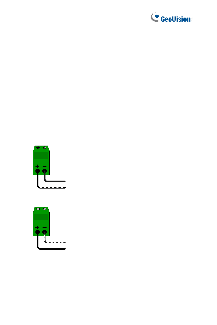
Plug the power adaptor to the terminal block as shown below. For all
models (except GV-BL2511-E / 5311-E), insert the striped wire to the
left pin (+); for GV-BL2511-E / 5311-E, insert the striped wire to the
right pin (-).
Figure 2-18 (All Models except GV-BL2511-E / 5311-E)
Figure 2-19 (GV-BL2511-E / 5311-E)
Bullet Camera (Part II)
37
2
I/O Device Connection
The camera supports one digital input and one digital output of dry contact.
Pin Function
1 Digital Output
2 GND
I/O
1
2
3
Figure 2-18
3 Digital Input
For details on how to enable an installed I/O device, see 4.2 I/O Settings,
GV-IPCam Firmware Manual.
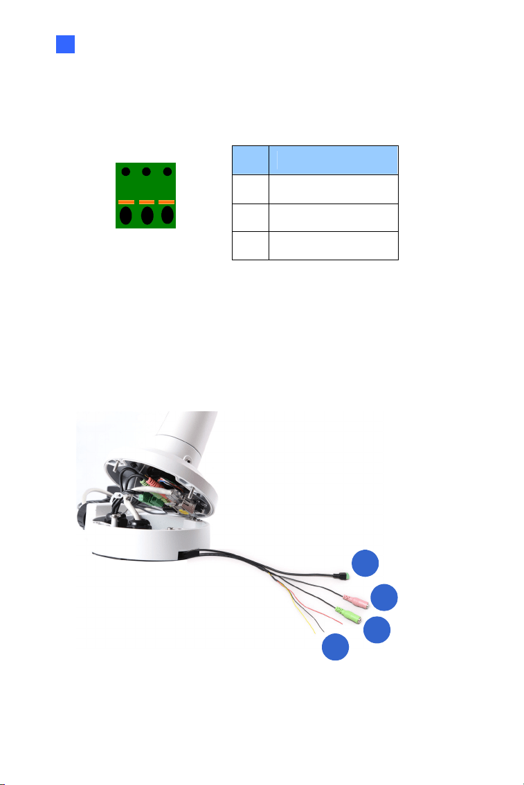
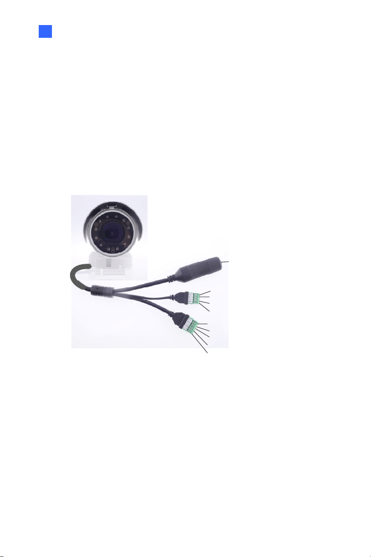
I/O Cable (Optional)
For GV-BL2702 / 4702 / 4713 / 5713, you can optionally purchase an I/O
cable for convenient connection.
1
2
3
4
Figure 2-17
38
No. Wire Definition
1 2-pin Terminal Block DC 12V
2 Pink RCA Audio Input
3 Green RCA Audio Output
Red Digital Output
Black GND
4 Digital I/O
Yellow Digital Input
Note: To connect a power adapter to the I/O cable, take off the 2-pin
terminal block on the adapter and connect the wires to the one on the I/O
cable.
39
Chapter 3 Bullet Camera (Part III)
The Bullet Cameras are specifically designed for outdoors. They are
weatherproof (IP67) and equipped with IR LEDs for infrared illumination in
night vision applications. They support H.265 video codec to achieve better
video compression while maintaining high quality picture. The cameras use
P-Iris, which allows for precise control of exposure, producing images with
better clarity and contrast
Model No. Specifications Description
GV-BL3700
P-Iris, f: 2.8 ~ 12 mm,
F/1.7, 1/2.7”, ø 14 mm
Lens Mount
3 MP, H.265,
Super Low
Lux, WDR
pro
GV-BL5700
Varifocal
Lens
P-Iris, f: 4 ~ 8 mm, F/1.65,
1/1.8”, ø 14 mm Lens
Mount
5 MP, H.265,
Low Lux,
WDR
Bullet Camera (Part III)
3
40
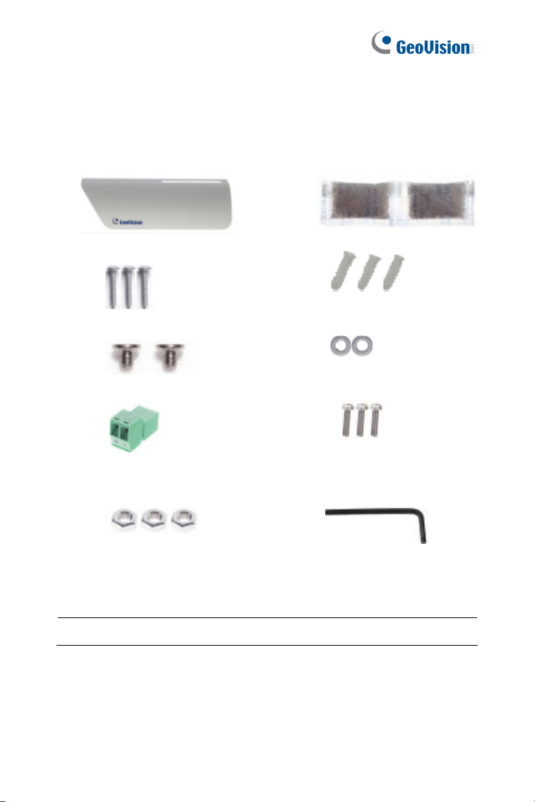
3.1 Packing List
H.265 Bullet Camera
Sun-shield Cover Screw for Sunshield
Cover x 2
Screw for Supporting Rack
x 3
Screw Anchor x 3
Silica Gel Bag x 2 Washer x 2
RJ-45 Connector x 2 Hex Wrench
Screw for Mounting Kit x 3 Nut for Mounting Kit x 3
Download Guide Warranty Card
Note: The Mounting Kit is used for wall corner and pole installations
using GV-Mount300 / 310 / 400 / 410 (optional). For details, see GV-
Mount Accessories Installation Guide.
Bullet Camera (Part III)
41
3
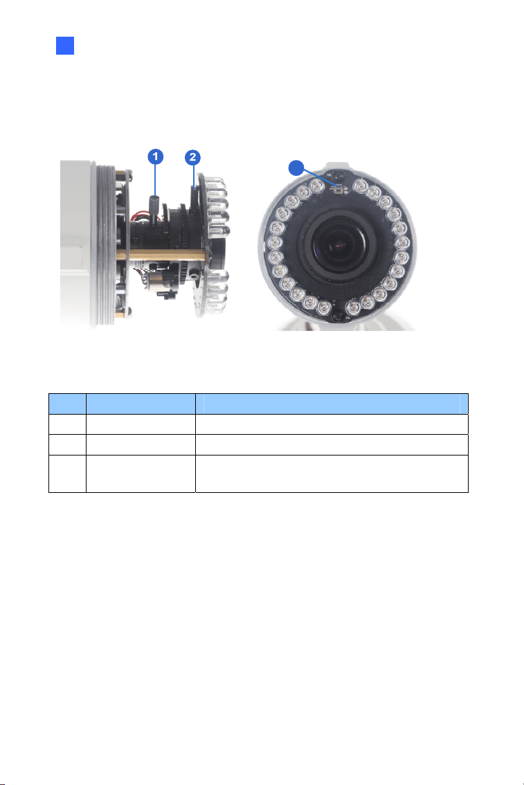
3.2 Overview
1
432
Figure 3-1
No. Name Description
1.
Memory Card
Slot
Receives a micro SD card (SD/SDHC/SDXC/
UHS-I, Class 10).
* UHS-II card type is not supported.
2. Default Button
Resets all configurations to factory default. For
details, see 3.5 Loading Factory Default.
3. Focus Screw Holds the focus lens in place
4. Zoom Screw Holds the zoom lens in place.
42
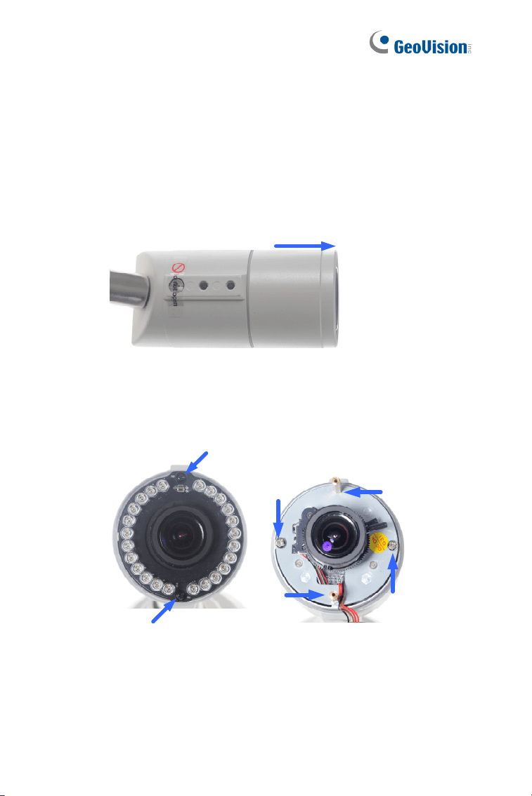
3.3 Installation
You can install the camera to the ceiling or wall. Follow the steps below.
1. Unscrew the camera body, remove the sun-shield mount, and
loosen the camera cover from the camera.
Screws
Sun-Shield Mount
Camera Cover
Figure 3-2
2. Insert a micro SD card (SD/SDHC/SDXC/UHS-I, Class 10) into the
card slot.
3. Tape two silica gel bags to the camera module.
Silica Gel Bag
Micro SD Card
Figure 3-3
Bullet Camera (Part III)
43
3
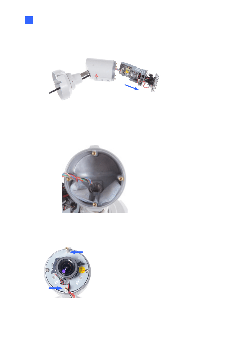
4. Secure the camera cover, fasten the sun-shield mount, and screw
the camera body.
Figure 3-4
5. Slide the sun-shield cover onto the top of the camera. Adjust the
position of the cover before fully securing the cover with the washer
and the screw.
Figure 3-5
Sun-Shield Mount
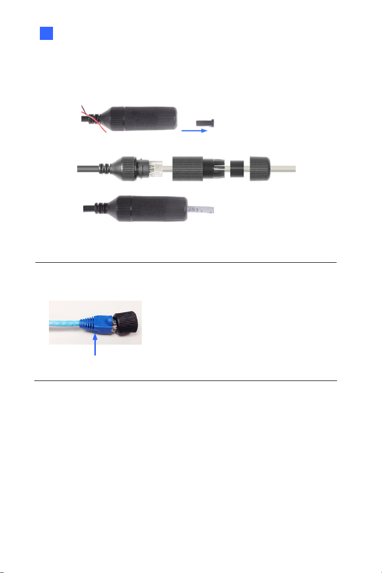
44
6. Thread the Ethernet cable into the conduit connector.
A. Remove the plug from the conduit connector.
Figure 3-6
B. Disintegrate the removed conduit connector. Thread the
Ethernet cable through the 3 parts.
Figure 3-7
C. Assemble the conduit connector.
Figure 3-8
Note: If you can’t plug the self-prepared RJ-45 connector into the jack of
the conduit, it is suggested to use the supplied RJ-45 connector.
Bullet Camera (Part III)
45
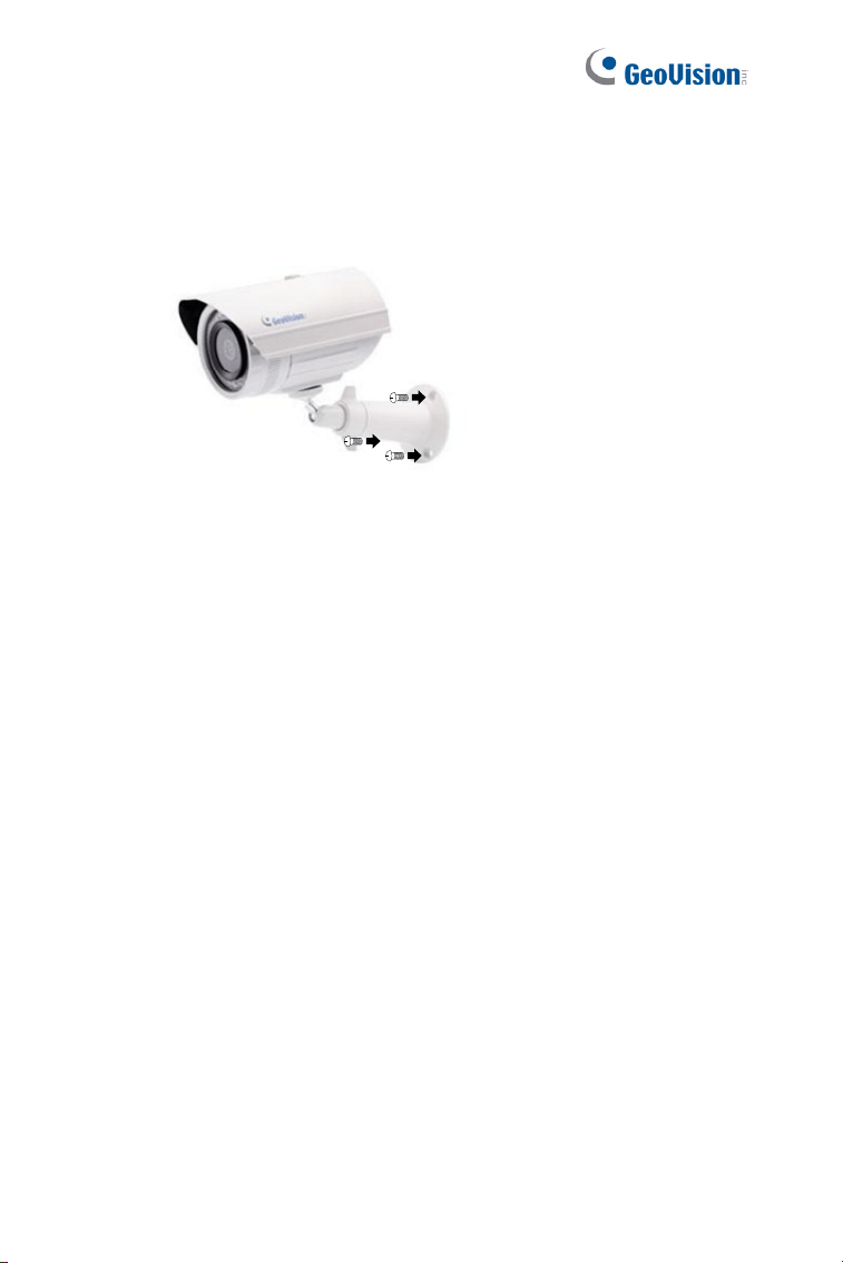
3
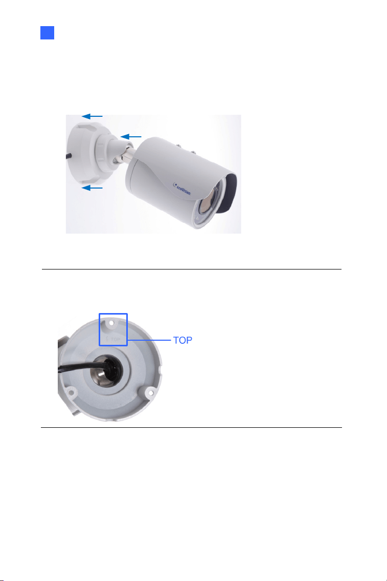
7. Install the camera to the wall or ceiling using the screw anchors and
screws for supporting rack.
Figure 3-9
IMPORTANT: To avoid waterproofing failures, the top of the camera
must be facing upward for wall mount.
8. Connect the wires and cable connector to the camera. See 3.4
Connecting the Camera.
9. Access the live view. For details, see 8.2 Accessing the Live View.
10. Adjust angles of the camera body based on the live view.
46
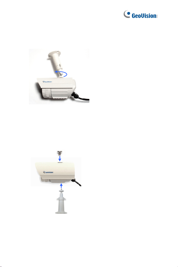
3.3.1 Adjusting the Angles
The GV-BL3700 / 5700 is designed to be adjustable in two shafts for easy
and flexible installation.
First Shaft
You can adjust the camera base by 360°.
1. Unscrew the base fixing screw with the hex wrench.
Figure 3-10
2. Adjust the angle of camera base, and fasten the base fixing screw
with the hex wrench.
Figure 3-11
Bullet Camera (Part III)
47
3
Second Shaft
You can adjust the camera body to the desired angle by tilting the camera
module.
1. Unscrew the tilting lock screw with the hex wrench.
Figure 3-12
2. Adjust the angle of camera body to the desired angle.
Figure 3-13
3. Fasten the tilting lock screw.
48
3.3.2 Adjusting Lens
To adjust the camera’s zoom and focus, follow the steps below.
Loosen the camera’s cover. See Figure 3-2.
To adjust for image clarity by adjusting the focus and zoom screws.
For details, see 8.3 Adjusting Image Clarity.
Zoom Screw
Focus Screw
Figure 3-14
Bullet Camera (Part III)
49
3
3.4 Connecting the Camera
3.4.1 Wire Definition
The 4-Pin terminal block supports 1 digital input and 1 digital output of dry
contact. For details on how to enable an installed I/O device, see 4.2 I/O
Settings, GV-IPCam Firmware Manual. The 5-Pin terminal block provides
power input, 1 audio input and 1 audio output. The wires are illustrated and
defined below:
Ethernet (PoE)
4-Pin terminal block
5-Pin terminal block
1
2
3
4
5
6
7
8
9
Figure 3-16
50
No. Wire Name Definition
1. DI - Digital In -
2. DI + Digital in +
3. DO - Digital Out -
4.
4-pin
terminal
block
DO+ Digital Out +
5. 12V 12 V DC
6. GND DC 12V +
7. L-IN Audio in
*Support passive microphones only
8. A GND Audio Ground
9.
5-pin
terminal
block
L-OUT Audio out
Wire Definition
RJ-45 Ethernet / PoE (IEEE 802.3af)
Note: To connect an audio input/output device, cut its 3.5 mm audio jack,
and connect the wires to L-IN and A GND for a microphone or L-OUT and
A GND for a speaker.
Figure 3-17
Bullet Camera (Part III)
51
3
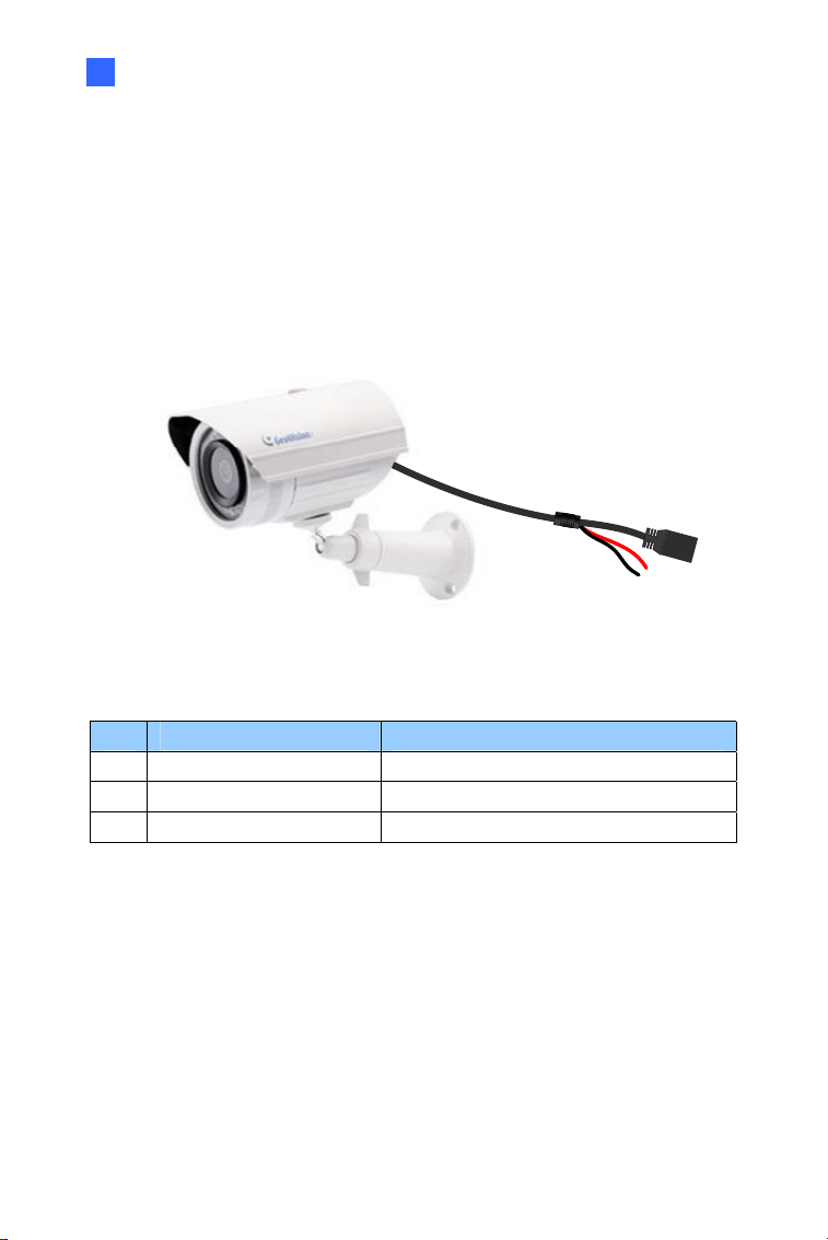
3.4.2. Power Connection
Use one of the following methods to supply power to the camera.
Use a Power over Ethernet (PoE) adapter to connect the camera
to the network, and the power will be provided at the same time.
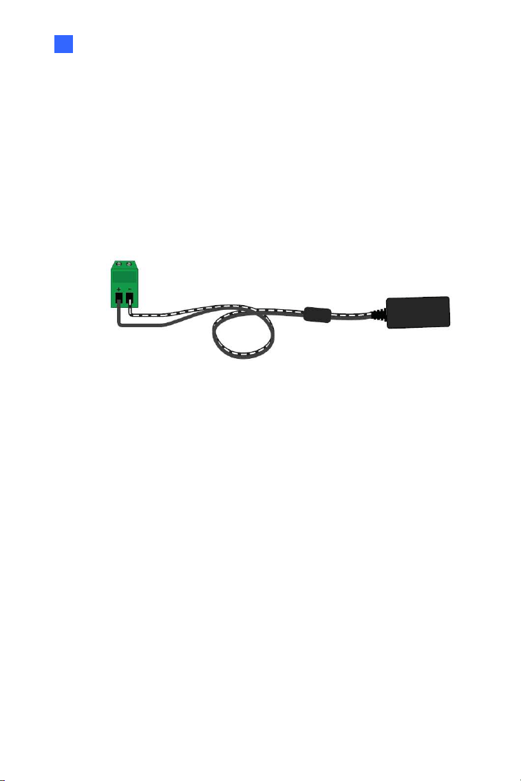
Connect the wires of your power adapter to the DC 12V+ and DC
12V- pins of the 5-pin terminal blocks.
Figure 3-18
52
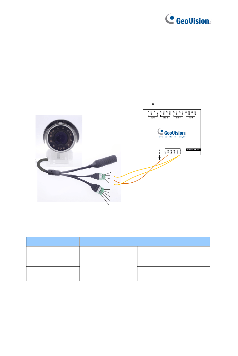
Voltage Load Expansion (Optional)
The camera can only drive a maximum load of 200mA 5V DC. To expand
the maximum voltage load to 10A 250V AC, 10A 125V AC or 5A 100V DC,
connect the camera to a GV-Relay V2 module (optional product). Refer to
the figure and table below.
Output Devices
Connect to Power
1
2
3
4
5
6
7
8
9
Figure 3-19
GV-Relay V2 Bullet Camera
COM
Digital In +
Digital Out +
DO1
4-Pin terminal block
Digital Out -
Bullet Camera (Part III)
53
3
3.5 Loading Factory Default
3.5.1. Using the Web Interface
U You can restore factory default settings through the Web interface. For
details, refer to 1.4.1 Using the Web Interface.
3.5.2. Directly on the Camera
Press and hold the default button for about 5 seconds to restore the
factory default. After the ready LED blinks, release the default button. For
details see 1.4.2 Directly on the Camera.
Default Button
LED status
Figure 3-20
54
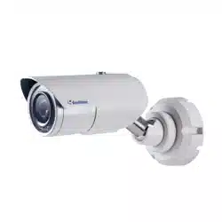
Chapter 4 Ultra Bullet Camera
The Ultra Bullet Camera is a series of light-weighted cameras designed for
outdoor environments. The camera adheres to the IP67 standard and has
full protection against dust and jets of water. The Ultra Bullet Cameras are
available in motorized varifocal lens and fixed lens at 1.3, 2 and 3
megapixels. The motorized varifocal lens models allow the user to
remotely adjust the focus and zoom through the Web interface. The WDR
Pro models can enhance the live view by processing contrasting intensity
of lights. The super low lux models are able to provide color live view in
near darkness.
Model No. Specifications Description
GV-UBL1211
1.3 MP Low Lux,
H.264, 3X Optical
Zoom
GV-UBL1511
1.3 MP Super Low
Lux, H.264, 3X Optical
Zoom
GV-UBL2411
2 MP, H.264, WDR
Pro, 3X Optical Zoom
GV-UBL2511
2 MP Super Low Lux,
H.264, 3X Optical
Zoom
GV-UBL3411
Varifocal
Lens
Auto Iris, f: 3 ~ 9
mm, F/1.2, 1/2.7’’
ø 14 mm Lens
Mount
3 MP, H.264, WDR
Pro, 3X Optical Zoom
Ultra Bullet Camera
55
4
Model No. Specifications Description
GV-UBL1301-0F
Fixed Iris, f: 2.8 mm,
F/2.0, 1/3’’ M12 Lens
Mount
GV-UBL1301-1F
Fixed Iris, f: 4 mm,
F/1.5, 1/3’’ M12 Lens
Mount
1.3 MP, Low
Lux, H.264
GV-UBL1301-2F
GV-UBL1301-3F
Fixed Iris, f: 4 / 8 mm,
F/1.6, 1/3’’ M12 Lens
Mount
1.3 MP, Low
Lux, H.264
GV-UBL2401-0F
Fixed Iris, f: 2.8 mm,
F/2.0, 1/3’’ M12 Lens
Mount
GV-UBL2401-1F
Fixed Iris, f: 4 mm,
F/1.5, 1/3’’ M12 Lens
Mount
GV-UBL2401-2F
GV-UBL2401-3F
Fixed Iris, f: 8 / 12 mm,
F/1.6, 1/3’’ M12 Lens
Mount
2 MP, H.264,
WDR Pro
GV-UBL3401-0F
Fixed Iris, f: 2.8 mm,
F/2.0, 1/3’’ M12 Lens
Mount
GV-UBL3401-1F
Fixed Iris, f: 4 mm,
F/1.5, 1/3’’ M12 Lens
Mount
GV-UBL3401-2F
GV-UBL3401-3F
Fixed
Lens
Fixed Iris, f: 8 / 12 mm,
F/1.6, 1/3’’ M12 Lens
Mount
3 MP, H.264,
WDR Pro

56
4.1 Packing List
Ultra Bullet Camera (with Waterproof or Non-Waterproof LAN
connector)
Camera Stand
Black Rubber
Self Tapping Screw x 3
Plastic Screw Anchor x 3
Torx Wrench
Sun-Shield Cover Kit (Sun-Shield Cover, Philips Head Screw x 2,
Plastic Screw Spacer x 2 and Hexagon Screw x 2)
Cable connector (for waterproof LAN connector only)
Silica Gel Bag x 2
2-Pin Terminal Block
Data cable
Power Adapter
Download Guide
Warranty Card
Note: The power adapter can be excluded upon request.
Ultra Bullet Camera
57
4
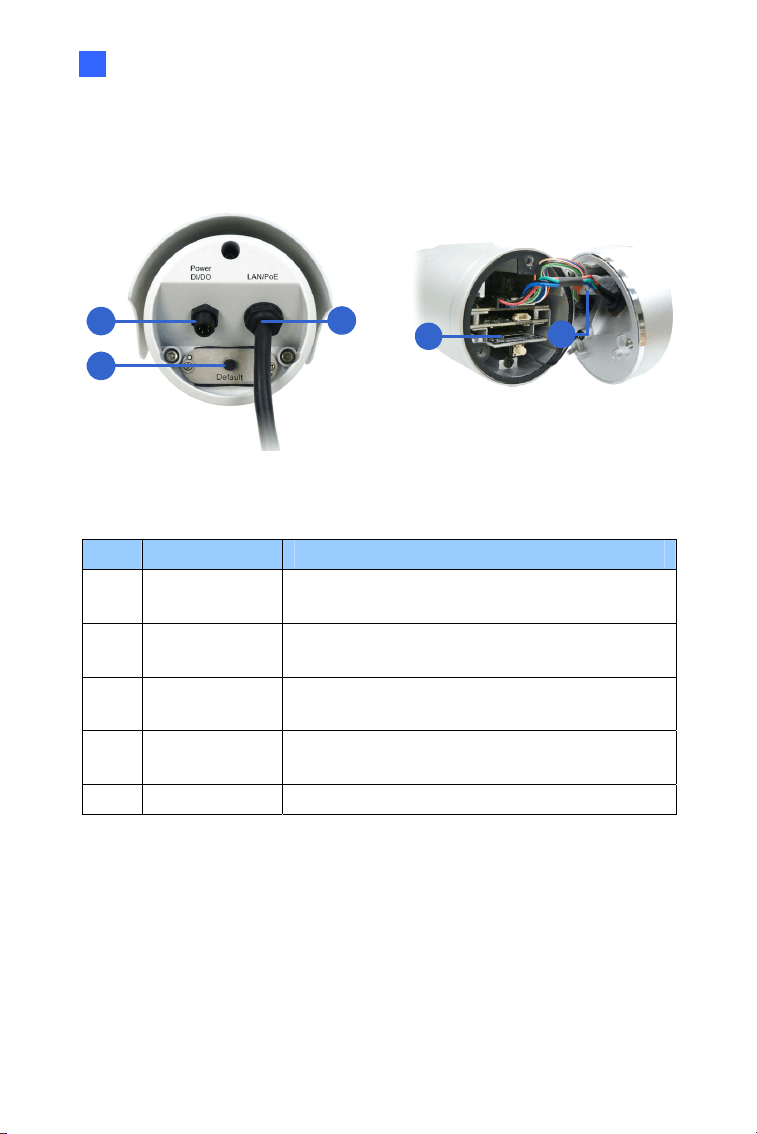
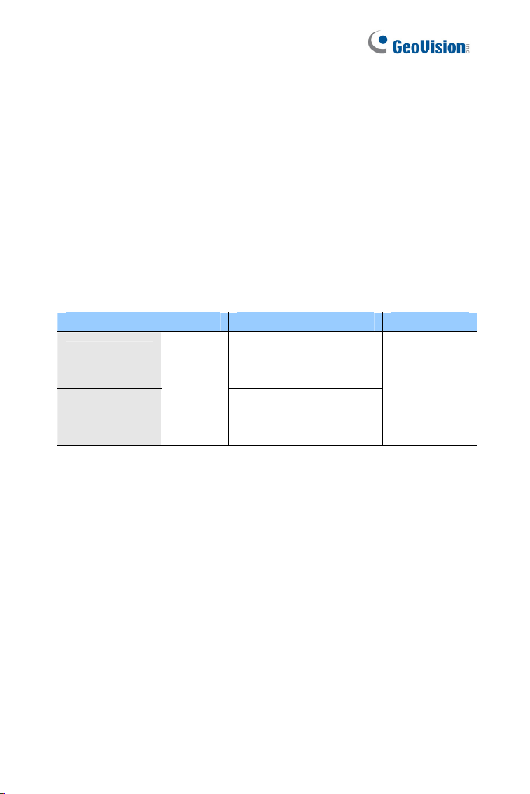
4.2 Overview
Panel
1
2
3
4
5
Figure 4-1
No. Name Description
1
Power & I/O
Connector
Connects to the data cable. For details, see
4.3.2 Connecting the Camera.
2 Default Button
Resets all configurations to factory default. For
details, see 4.4 Loading Factory Default.
3
LAN / PoE
Cable
Connects to a 10/100 Ethernet or PoE.
4
Memory Card
Slot
Receives a micro SD card (SD/SDHC, version
2.0 only, Class 10).
5 Silica gel bag Desiccant that keeps the camera housing dry.
58
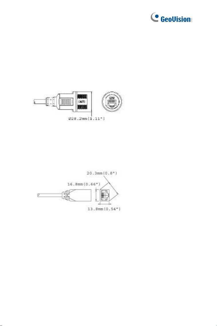
LAN Connector
The Ultra Bullet Camera provides two connector types. Select an option
based on your installation environment.
Option 1 (Waterproof)
To waterproof the cable, install the supplied cable connector. See 4.3.1
Waterproofing the Cable.
Option 2 (Smaller and non-waterproof)
Ultra Bullet Camera
59
4
4.3 Installation
You can install the camera to the ceiling or wall. Follow the steps below.
1. Optionally insert a micro SD card to the camera.
A. Unscrew and open the back panel with the supplied torx wrench.
Figure 4-2
B. Insert a micro SD card into the card slot and replace the silica
gel bag (see Figure 4-1).
IMPORTANT: Make sure the I/O connector is firmly plugged.
C. Secure the back cover with the supplied torx wrench.
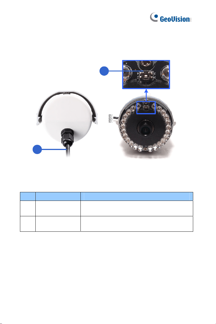
2. Install the sun-shield cover to the camera.
60
A. Fasten the hexagon screw(s) on the top of the camera.
Figure 4-3
B. Put the sun-shield cover on the top of the camera. For optimal
sun-shield performance, make sure the rear hexagon screw is at
the end of the opening.
Figure 4-4
IMPORTANT: The GeoVision logo on the sun-shield cover should
be closer to the front of the camera.
Hexa
g
on Screws
Sun-Shield Cover
Ultra Bullet Camera
61
4
C. Fasten the Philips head screws with the plastic screw spacers to
mount the sun-shield cover onto the camera.
Ceiling Mount: Fasten one Philips head screw to the top
of the camera.
Wall Mount: Fasten two Philips head screws to the top
of the camera.
Philips Head Screw
Plastic Screw Spacer
Figure 4-5
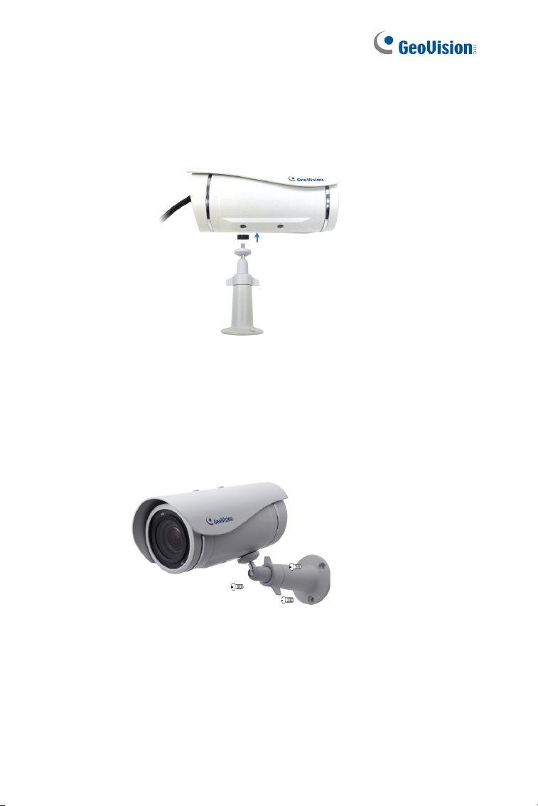
3. Install the camera stand.
A.
Ceiling Mount: Secure the black rubber and the camera stand to
the screw hole on the top.
Figure 4- 6
62
B. Wall Mount: Secure the black rubber and the camera stand to
one of the screw holes on the bottom.
Figure 4-7
4. Use the screw anchors and self-tapping screws to secure the
camera to the wall.
Figure 4-8

Ultra Bullet Camera
63
4
5. Remove the protection sticker from the camera’s cover.
6. Connect the wires and cable connector to the camera. See 4.3.1
Waterproofing the Cable and 4.3.2 Connecting the Camera.
7. Access the live view. For details, see 8.2 Accessing the Live View.
8. Adjust angles of the camera body based on the live view.
9. For varifocal models (GV-UBL1211 / 1511 / 2411 / 2511 / 3411),
adjust the focus. For details, see 3.2.2 The Control Panel of the Live
View Window, GV-IPCam Firmware Manual.
64
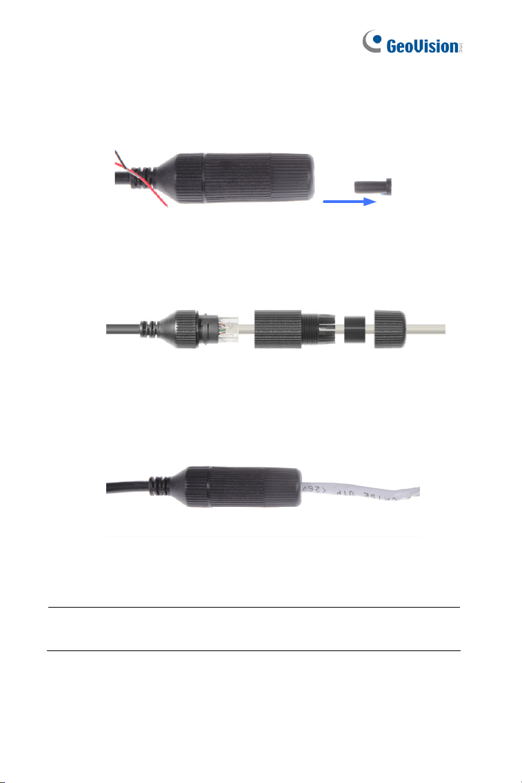
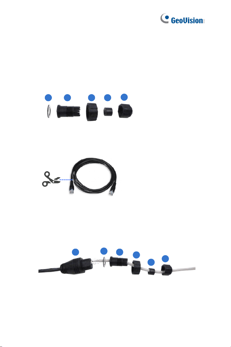
4.3.1 Waterproofing the Cable
Waterproof the option 1 LAN / PoE cable (see 4.2 Overview) using the
supplied cable connector. The cable connector can be dissembled into 5
parts:
1 2 3 4
5
Figure 4-9
1. Cut off the RJ-45 connector on one end of the Ethernet cable.
Figure 4-10
2. Connect the Ethernet cable to the LAN / PoE connector (No. 3,
Figure 4-1) on the camera.
3. Slide the components through the Ethernet cable as shown below.
1
2
3
4
5
A
Figure 4-11
4. Paste the item 1 sticker to item 2.

Ultra Bullet Camera
65
4
5. Move all the components toward the LAN / PoE connector, fit item 4
to item 2, secure item 3 to the LAN / PoE connector (Item A) and
finally secure item 5 to item 2 tightly.
Figure 4-12
IMPORTANT: Item 5 must be secured tightly to waterproof the
LAN / PoE connector.
6. Prepare an RJ-45 connector, reconnect the RJ-45 connector to the
cable, and then connect the camera to network.
66
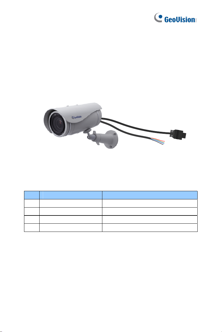
4.3.2 Connecting the Camera
Wire Definition
The camera’s 4-pin data cable provides connections for power, ground, 1
sensor input and 1 alarm output. The wires are defined below:
Figure 4-13
No. Wire Color Definition
1 Red DC 5V
2 Green Digital In
3 Blue Digital Out
4 Black Ground
Ultra Bullet Camera
67
4
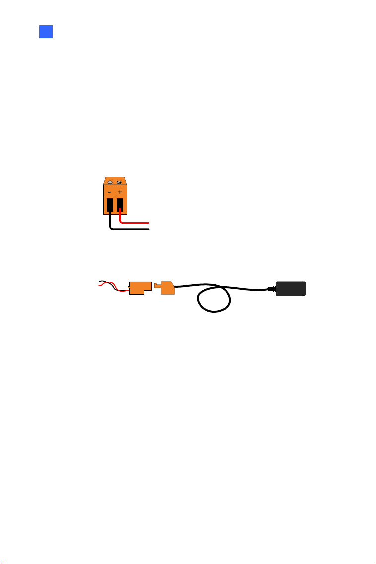
Power Connection
Connect the camera to power using one of the following methods:
Use a Power over Ethernet (PoE) adapter to connect the camera to
the network, and the power will be provided at the same time.
Plug the power adaptor to the terminal block as shown below.
1. Insert the black wire of the data cable to the left pin (-) and
the red wire to the right pin (+).
Figure 4-14
2. Connect the DC 5V power adapter to the terminal block.
DC 5V Power Adaptor
Terminal Block
Figure 4-15
68
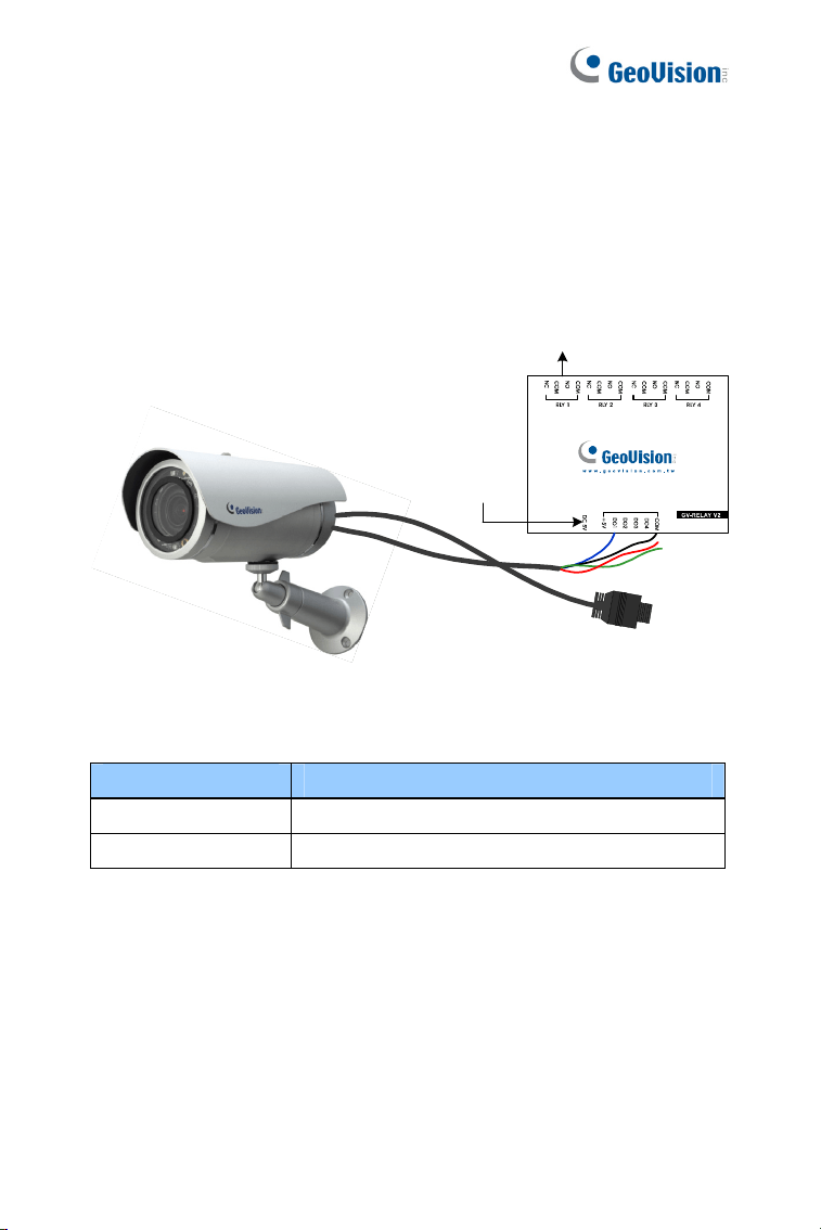
Voltage Load Expansion (Optional)
The camera can only drive a maximum load of 200mA 5V DC. To expand
the maximum voltage load to 10A 250V AC, 10A 125V AC or 5A 100V DC,
connect the camera to a GV-Relay V2 module (optional product). Refer to
the figure and table below.
Output Devices
Connect
to power
Figure 4-16
GV-Relay V2 Ultra Bullet Camera
DO1 Digital Out (Blue)
COM Ground (Black)
Ultra Bullet Camera
69
4
4.4 Loading Factory Default
4.4.1 Using the Web Interface
You can restore factory default settings through the Web interface. For
details, refer to 1.4.1 Using the Web Interface.
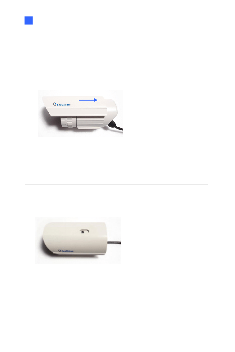
4.4.2 Directly on the Camera
Press and hold the default button for about 8 seconds to store the factory
default. For details see 1.4.2 Directly on the Camera.
Figure 4-17
Default button
70
Chapter 5 Target Bullet Camera
(Part I)
The Target Bullet Camera is a series of light-weighted cameras designed
for outdoor environments. The camera adheres to the IP67 standard and
has full protection against dust and jets of water. The camera offers an
entrylevel surveillance solution with all the essential features and excellent
image quality.
Model No. Specifications Description
GV-EBL1100-1F
GV-EBL2100-1F
Fixed Iris, f: 6 mm,
F/1.8, 1/2.7”, ø 14 mm
Lens Mount
GV-EBL1100-2F
GV-EBL2100-2F
Fixed
Lens
Fixed Iris, f: 3.8 mm,
F/1.8, 1/2.7”, ø 14 mm
Lens Mount
1.3 MP / 2 MP,
H.264, Low
Lux

Target Bullet Camera (Part I)
71
5
5.1 Packing List
Target Bullet Camera
Sun-Shield Cover
Silica Gel Tape x 2
Supporting Rack
Screw for supporting rack x 3
Screw Anchor x 3
Screw for sun-shield cover
Washer
Terminal Block
Download Guide
Warranty Card
Note: Power adapter can be purchased upon request.
72
5.2 Overview
2
1
Figure 5-1
No. Name Description
1
Power
Connector
Connects to the data cable. For details, see
5.4 Connecting the Camera.
2 Default Button
Resets the camera to factory default. For
details, see 5.5 Loading Factory Default.
Target Bullet Camera (Part I)
73
5
5.3 Installation
You can install the camera to the ceiling or wall. Follow the steps below.
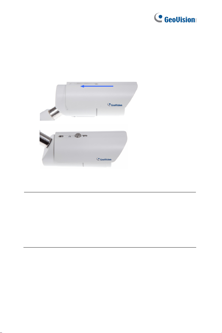
1. Slide the sun-shield cover onto the top of the camera.
Figure 5-3
Note: The GeoVision logo on the sun-shield cover should be closer to
the front of the camera.
2. Line up the screw hole on the camera with the opening on the sun-
shield cover.
Figure 5-4
74
3. Ceiling Mount: Secure the supporting rack to the opening on the
sun-shield cover
Figure 5-5
4. Wall Mount:
A. Insert and tighten the supplied screw and washer on the sun-
shield cover.
B. Secure the supporting rack to the bottom.
Figure 5-6
Target Bullet Camera (Part I)
75
5
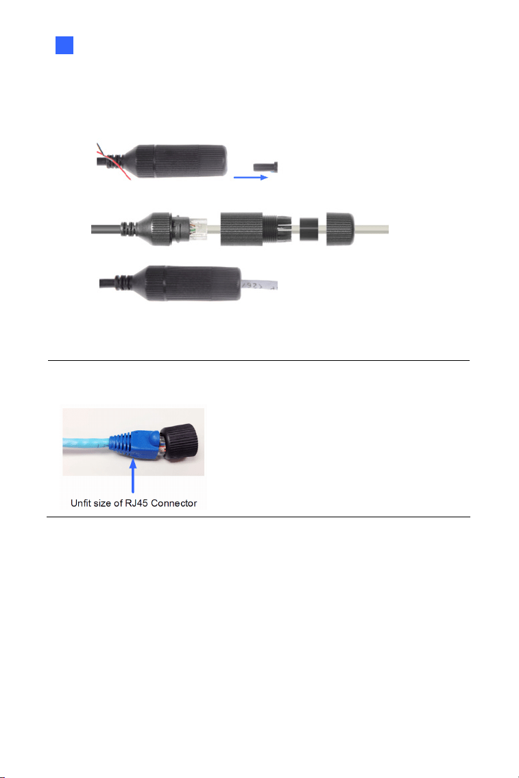
5. Thread the Ethernet cable into the conduit connector. For details,
see step 6, 3.3 Installation.
Figure 5-7
Note: The size of RJ-45 connector must be within 14 mm to plug into the
jack of the conduit.
Unfit size of RJ45 Connector
76
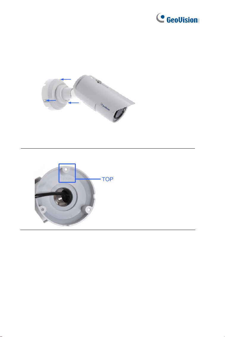
6. Install the camera to the wall or ceiling using the screw anchors and
self-tapping screws. You can also stand the camera on a plain
surface.
Figure 5-8
7. Remove the protection sticker from the camera’s cover.
8. Connect the wires and cable connector to the camera. See 5.4
Connecting the Camera.
9. Access the live view. For details, see 8.2 Accessing the Live View.
10. Adjust angles of the camera body based on the live view.
Target Bullet Camera (Part I)
77
5
5.4 Connecting the Camera
5.4.1 Wire Definition
The data cable provides connections for power, ground and network
access. The wires are defined below:
Figure 5-9
No. Wire Color Definition
1 Red DC 12V
2 Black Ground
3 Black (thick) PoE, Ethernet
78
5.4.2 Power Connection
There are two ways to supply power to the camera:
Use a Power over Ethernet (PoE) adapter to connect the camera to
the network, and the power will be provided at the same time.
Plug the power adapter to the 12V terminal block as shown below.
The power adapter is an optional device.
1. Insert the black wire of the data cable to the left pin (-) and the red
wire to the right pin (+).
+-
Figure 5-10
2. Connect the DC 12V power adapter to the terminal block.
DC 12V Power Adaptor
Terminal Block
Figure 5-11
Note: The Power Adaptor is not supplied in the packing list. You need
to self-prepare this item.
Target Bullet Camera (Part I)
79
5
5.5 Loading Factory Default
5.5.1 Using the Web Interface
3. On the left menu of Web interface, select Management and select
Tools. The Additional Tools dialog box appears.
4. Click the Load Default button of Restore to factory default
settings or Restore to factory default settings (Except network)
in the System Settings section.
Figure 5-12
Note: The Restore to factory default settings (Except network)
option is to restore the factory default settings without changing the
camera’s network settings.
80
5.5.2 Directly on the Camera
Press and hold the default button for about 8 seconds to restore the
factory default. For details see 1.4.2 Directly on the Camera.
Default button
Figure 5-13
Target Bullet Camera (Part II)
81
6
Chapter 6 Target Bullet Camera
(Part II)
The Target Bullet Camera is a light-weighted camera designed for outdoor
environments. It adheres to the IP67 standard and has full protection
against dust and jets of water. The camera also allows automatic and
precise control of exposure using its P-iris, producing images with better
clarity and contrast. It offers an entrylevel surveillance solution with all the
essential features and excellent image quality.
Model No. Specifications Description
GV-EBL2101
Varifocal
Lens
P-Iris, f: 3 ~ 9 mm,
F/1.7, 1/2.7”, ø 14 mm
Lens Mount
2 MP, H.264,
Super Low
Lux
GV-EBL2111
Motorized
Varifocal
Lens
P-Iris, f: 2.8 ~ 12 mm,
F/1.7, 1/2.7”, ø 14 mm
Lens Mount
2 MP, H.264,
Super Low
Lux
GV-EBL3101
Varifocal
Lens
P-Iris, f: 2.8 ~ 12 mm,
F/1.7, 1/2.7”, ø 14 mm
Lens Mount
3 MP, H.264,
Super Low
Lux
GV-EBL5101
Varifocal
Lens
P-Iris, f: 2.8 ~ 12 mm,
F/1.7, 1/2.7”, ø 14 mm
Lens Mount
5 MP, H.264 ,
Low Lux
82
6.1 Packing List
Target Bullet Camera
Sun-shield Cover
Silica Gel Bag x 2
Screw for Supporting Rack
x 3
Screw Anchor x 3
Screw for Sun-shield Cover
x 2
Washer x 2
Terminal Block
Screw for Mounting Kit x 3
Nut for Mounting Kit x 3
Hex Wrench
Download Guide
Warranty Card
Note: Power adapter can be purchased upon request.
Target Bullet Camera (Part II)
83
6
6.2 Overview
3
Figure 6-1
No. Name Description
1 Zoom Screw Holds the zoom lens in place.
2 Focus Screw Holds the focus lens in place
3 Default Button
Resets all configurations to factory default. For
details, see 6.5 Loading Factory Default.
84
6.3 Installation
You can install the camera to the ceiling or wall. Follow the steps below.
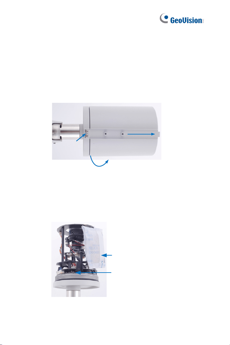
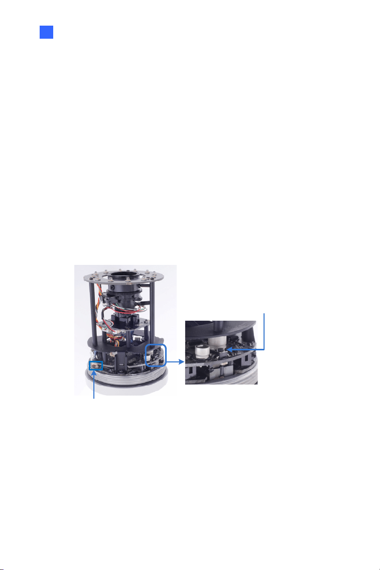
1. Replace the Silica Gel Bag.
A. Remove the camera cover from the camera.
Figure 6-2
B. Loosen the camera’s screws and the hexagon pillars as
indicated below.
Figure 6-3
Target Bullet Camera (Part II)
85
6
C. Take out the camera from the camera body
Figure 6-4
D. Cut the 2 silica gel bags apart with scissors, and place the
new silica gel bags at the lower half of the camera body.
Figure 6-5
2. Secure the 2 hexagon pillars to the upper and lower holes of camera
module as indicated below.
Figure 6-6
86
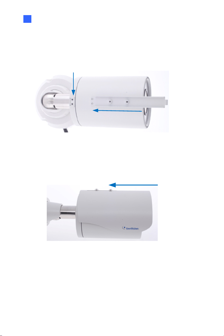
3. Secure the camera cover.
4. Slide the sun-shield cover onto the top of the camera. You can also
secure the sun shield cover onto the back of the camera. Adjust the
position of the cover before fully securing the cover with the washer
and the screw.
Figure 6-7
Note:
1. The GeoVision logo on the sun-shield cover should be closer to
the front of the camera.
2. There are two holes for the screws at the back of the camera.
You only need to fasten one screw to secure the sun shield
cover.
Target Bullet Camera (Part II)
87
6
5. Thread the Ethernet cable into the camera. For details, see step 6,
3.3 Installation.
Figure 6-8
Note: The size of RJ-45 connector must be within 14 mm to plug into the
jack of the conduit.
88
6. Install the camera to the wall or ceiling using the screw anchors and
screws for supporting rack.
Figure 6-9
7. Connect the wires and cable connector to the camera. See 6.4
Connecting the Camera.
8. Access the live view. For details, see 8.2 Accessing the Live View.
9. Adjust angles of the camera body based on the live view.
IMPORTANT: To avoid waterproofing failures, the top of the camera
must be facing upward for wall mount.
Target Bullet Camera (Part II)
89
6
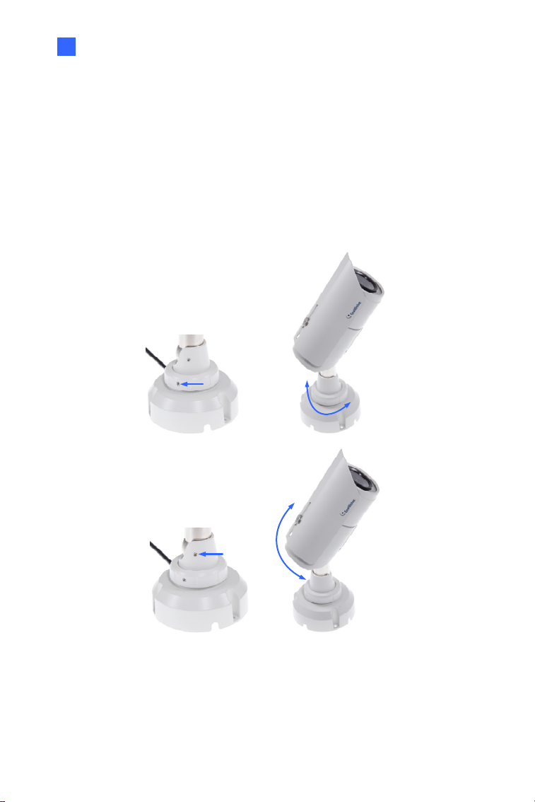
6.3.1 Adjusting the Angles
The Target Bullet Camera is designed to be adjustable in two shafts for
easy and flexible installation.
You can adjust the camera base by 360° and the camera body to the
desired angle by tilting the camera module. For details, see 3.3.1
Adjusting
the Angles.
360°
Figure 6-10
90
6.3.2 Adjusting Lens
To adjust the camera’s zoom and focus, follow the steps below.
1. Loosen the camera’s cover. See Figure 6-2.
2. To adjust for image clarity by adjusting the focus and zoom screws.
For details, see 8.3 Adjusting Image Clarity.
Zoom Screw
Focus Screw
Figure 6-11
Target Bullet Camera (Part II)
91
6
6.4 Connecting the Camera
6.4.1 Wire Definition
The data cable provides connections for power, ground and network
access. The wires are defined below:
Figure 6-12
No. Wire Color Definition
1 Red DC 12V
2 Black Ground
3 Black (thick) PoE, Ethernet

92
6.4.2 Power Connection
For details, see 5.4.2 Power Connection.
Note: The Power Adaptor is not supplied in the packing list. The Power
adapter can be purchased upon request.
Target Bullet Camera (Part II)
93
6
6.5 Loading Factory Default
6.5.1 Using the Web Interface
You can restore factory default settings through the Web interface. For
details, see 5.5.1 Using the Web Interface.
6.5.2 Directly on the Camera
Press and hold the default button for about 8 seconds to load the factory
default. For details, see 1.4.2 Directly on the Camera.
Figure 6-13
94
Chapter 7 Target Bullet Camera
(Part III)
The Target Bullet Camera is a light-weighted camera designed for outdoor
environments. It adheres to the IP67 standard and has full protection
against dust and jets of water. The camera comes with a built-in micro SD
card slot for local storage. The camera can support H.265 video codec to
achieve better compression ratio while maintaining high quality pictures at
reduced network bandwidths. The camera is capable of providing a color
live view not only in near darkness but also under contrasting light
intensities with its super low lux CMOS image sensor and WDR pro.
Model No. Specifications Description
GV-EBL2702-1F
Fixed Iris, f: 6 mm,
F/2.0, 1/2.7”, M12 mm
Lens Mount
GV-EBL2702-2F
Fixed Iris, f: 3.8 mm,
F/1.8, 1/2.7”, M12 mm
Lens Mount
GV-EBL2702-3F
Fixed Iris, f: 2.8 mm,
F/2.0, 1/2.7”, M12 mm
Lens Mount
2MP, H.265,
Super Low
Lux, WDR Pro
GV-EBL4702-1F
Fixed Iris, f: 6 mm,
F/2.0, 1/2.7”, ø 12 mm
Lens Mount
GV-EBL4702-2F
Fixed
Lens
Fixed Iris, f: 3.8 mm,
F/1.8, 1/2.7”, ø 12 mm
Lens Mount
4 MP, H.265,
Super Low
Lux, WDR Pro
Target Bullet Camera (Part III)
95
7
GV-EBL4702-3F
Fixed Iris, f: 2.8 mm,
F/2.0, 1/2.7”, ø 12 mm
Lens Mount
GV-EBL4711
Motorized
varifocal
lens
P-Iris, f: 2.7 ~ 12 mm,
F/1.6, 1/2.7”, ø 14 mm
Lens Mount
4 MP, H.265,
Super Low
Lux, WDR Pro
7.1 Packing List
H.265 Bullet Camera
Sun-shield Cover
Silica Gel Bag x 2
Screw for Supporting Rack
x 3
Screw Anchor x 3
Screw for Sun-shield Cover
x 2
Washer x 2
Terminal Block
Hex Wrench
Screw for Mounting Kit x 3
Nut for Mounting Kit x 3
Download Guide
Warranty Card
Note: Power adapter can be purchased upon request.
96
7.2 Overview
Figure 7-1
No. Name Description
1 Default Button
Resets all configurations to factory default. For
details, see 7.5 Loading Factory Default.
2
Memory Card
Slot
Inserts a micro SD card
(SD/SDHC/SDXC/UHS-I) to store recording
data. Note UHS-II card type is not supported.
Note: GV-EBL2702 Series does not support SDXC cards.
Target Bullet Camera (Part III)
97
7
7.3 Installation
To install the camera to the ceiling or wall, you need to open the camera
body, insert the memory card, replace silica gel bag, install the sun-shield
cover, waterproof the cable, and adjust the camera angles. For details see
6.3 Installation and 6.3.1 Adjusting the Angles.
Note:
1. To avoid replacing the silica gel bag and installing the camera all
over again, make sure the SD card is installed properly in the first
place.
2. When installing the sun-shield cover, it is suggested to align the
front cover edge vertically with the camera lens cover in order to
avoid light reflex effects.
Figure 7-2

98
7.4 Connecting the Camera
7.4.1 Wire Definition
The data cable provides connections for power, ground and network
access. For details, refer to 6.4.1 Wire Definition.
7.4.2 Power Connection
For details, see 5.4.2 Power Connection.
Note: The Power Adaptor is not supplied in the packing list. Power
adapter can be purchased upon request.
Target Bullet Camera (Part III)
99
7
7.5 Loading Factory Default
7.5.1 Using the Web Interface
You can restore factory default settings through the Web interface. For
details, see 5.5.1 Using the Web Interface.
7.5.2 Directly on the Camera
Press and hold the default button for about 8 seconds to load the factory
default. For details, see 1.4.2 Directly on the Camera.
Figure 7-3

100
Chapter 8 Accessing the Camera
8.1 System Requirement
To access the GV-IP Camera through the Web browser, ensure your PC
connects to the network properly and meets this system requirement:
Microsoft Internet Explorer 8.0 or later
Note: For the users of Internet Explorer 8, additional settings are
required. For details, see Appendix A in GV-IPCAM Firmware Manual.

Accessing the Camera
101
8
8.2 Accessing the Live View
When the camera is connected to a network with a DHCP server, it will be
automatically assigned with a dynamic IP address. See 8.2.1 Checking the
Dynamic IP Address to look up this IP address.
However, if you do not have a DHCP server on your network, access the
camera by its default IP address 192.168.0.10 and see 8.2.2 Configuring
the IP Address for more detail.
102
8.2.1 Checking the Dynamic IP Address
Follow the steps below to look up the IP address and access the Web
interface.
Note:
1. The computer you use to configure the IP address must be under
the same LAN with your camera.
2. The default Administrator and Guest accounts are no longer
supported by GV-IPCam H.265 series firmware V1.14 or later.
When logging in for the first time, you need to set up a login
username and password for the camera. See Creating GV-IP
Camera’s Login Credentials at the beginning of the quick start
guide.
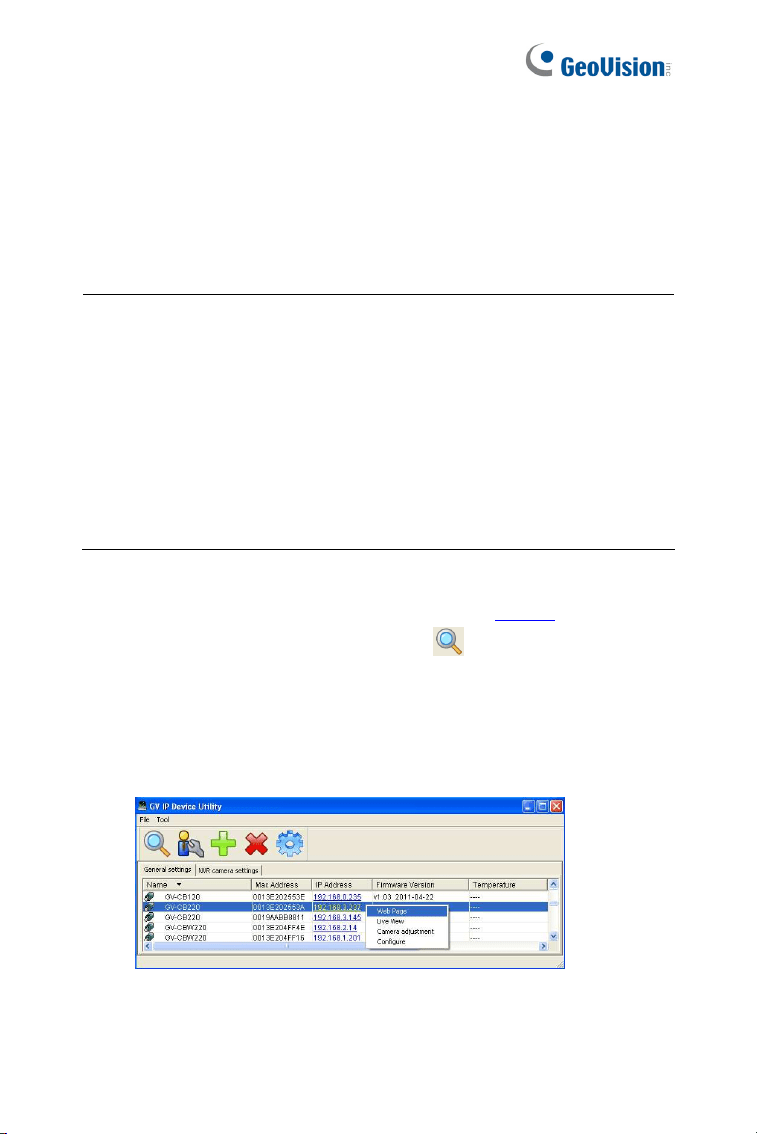
1. Install GV-IP Device Utility from the company website
2. On the GV-IP Utility window, click the
button to search for the IP
devices. Click the Name or Mac Address column to sort.
3. Find the camera with its Mac Address, click on its IP address and
select Web Page.
Figure 8-1
Accessing the Camera
103
8
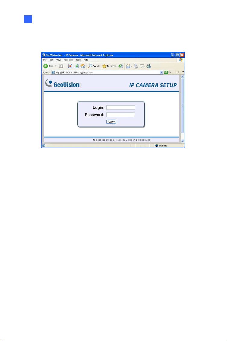
4. The login page appears.
Figure 8-2
5. Type the default ID and password admin and click Apply to log in.
104
8.2.2 Configuring the IP Address
Follow the steps below to configure the IP address.
1. Open your Web browser, and type the default IP address
http://192.168.0.10
.
2. In both Login and Password fields, type the default value admin.
Click Apply.
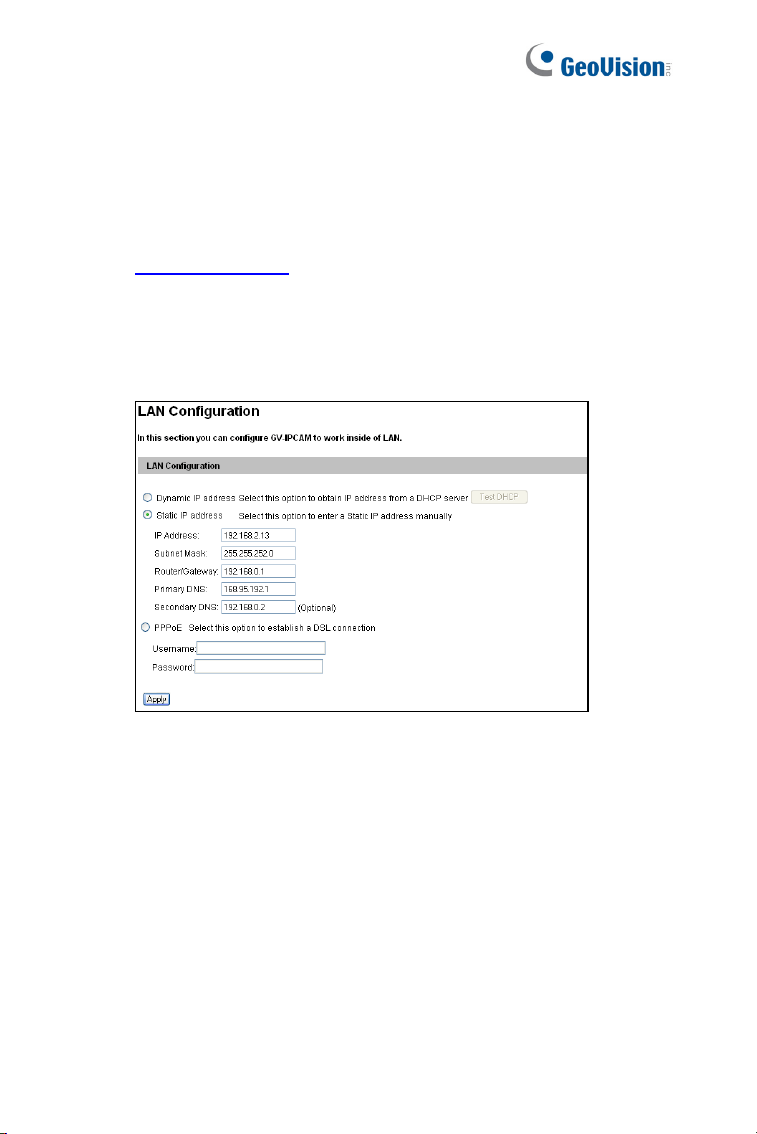
3. In the left menu, select Network and then LAN to begin the network
settings.
Figure 8-3
4. Select Static IP address, Dynamic IP address or PPPoE and type
the required network information.
5. Click Apply. The camera is now accessible by entering the
assigned IP address on the Web browser.
6. To enable the updating of images in Microsoft Internet Explorer, you
must set your browser to allow ActiveX Controls and perform a one-
time installation of GeoVision’s ActiveX component onto your
computer.

Accessing the Camera
105
8
IMPORTANT:
1. If Dynamic IP Address or PPPoE is enabled, you need to know
which IP address the camera will get from DHCP server or ISP
to log in. If your camera is installed in the LAN, use the GV-IP
Device Utility to look up its current dynamic IP address. See
8.2.1 Checking the Dynamic IP Address. If your camera uses a
public dynamic IP address via PPPoE, use the dynamic DNS
Service to obtain a domain name that is linked to the camera’s
changing IP address first. For details, see LAN Configuration
and Advanced TCP/IP sections, Administrator Mode Chapter in
the GV-IPCAM Firmware Manual.
2. If Dynamic IP Address or PPPoE is enabled and you cannot
access the camera, you may have to reset the camera to its
factory default and then perform the network settings again. To
restore factory settings, see 1.4 Loading Factory Default.
106
8.3 Adjusting Image Clarity
You can adjust the image clarity using the GV-IP Device Utility. Make sure
that you have connected your GV-IPCAM to the network and install the
GV-IP Device Utility program under the same LAN.
Note: This feature only applies to the cameras that allow manual focus
adjustment.
1. Make sure you have installed GV-IP Device Utility from the company
website
.
2. On the GV-IP Utility window, click the
button to search for the
IP devices connected in the same LAN. Click the IP Address of the
camera you desire. A drop-down list appears.
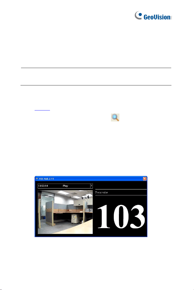
3. Select Focus Value. The Login dialog box appears.
4. Type the user name and password of the camera selected. The
default is admin for both user name and password. This window
appears.
Figure 8-4
5. Adjust the Zoom Screw and the Focus Screw of the camera slowly
until the focus value reaches the maximum.

Accessing the Camera
107
8
Note:
1. For locations of adjustment screws and rings in each model, see
Locations of Adjustment Screws, section, Getting Started
Chapter, GV-IPCAM Firmware Manual.
2. Do not over tighten the screws. The screws only need to be as
tight as your fingers can get them to be. Do not bother using any
tool to get them tighter. Doing so can damage the structure of
lens.
3. The maximum focus value may vary when the environment
changes.
108
Chapter 9 The Web Interface
1 2 3
4
5 6 7
8
9
10
11
12 13
Figure 9-1

The Web Interface
109
9
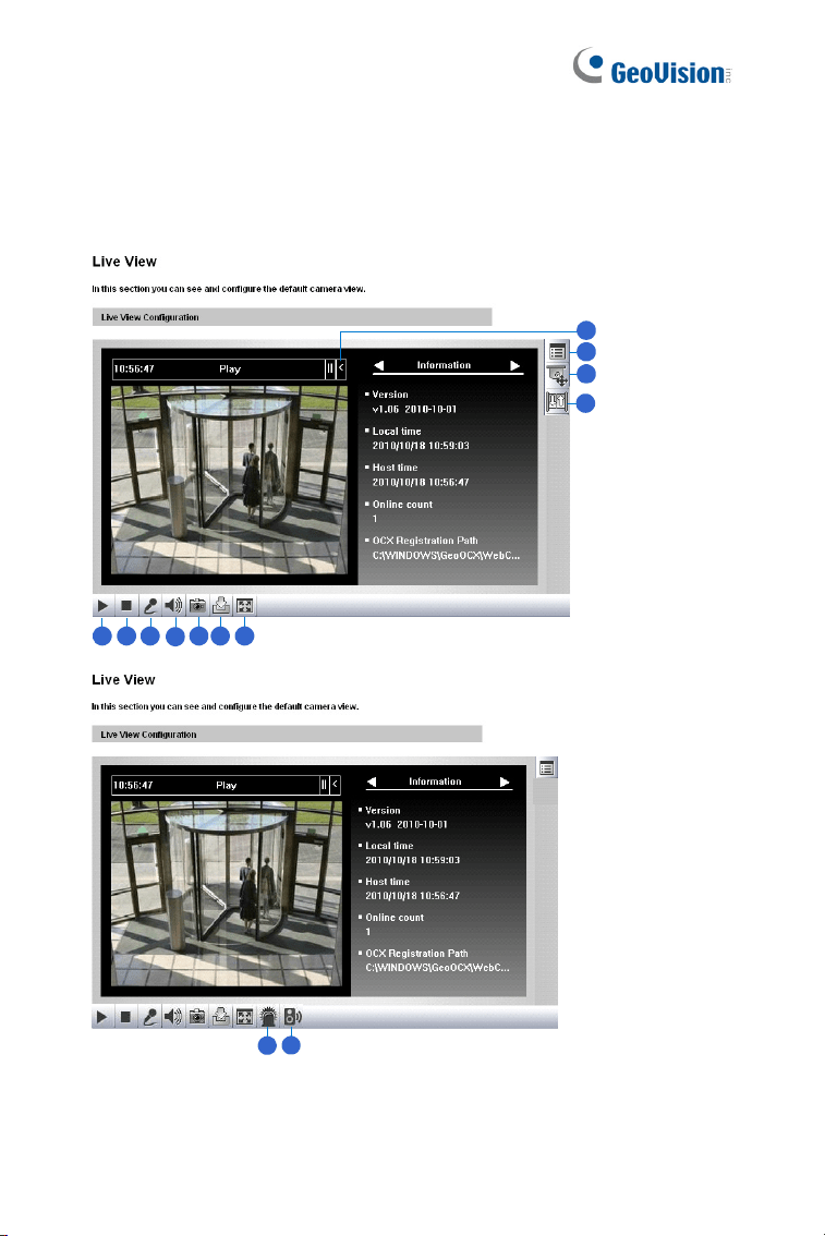
No. Name Function
1 Play Plays live video.
2 Stop Stops playing video.
3 Microphone
Broadcasts to the surveillance site from a remote
PC. Note this function is not available for Ultra
Bullet Camera and Target Series. For Cube
Camera and Advanced Cube Camera, click the
Push to talk button (from the pop-up menu) for the
camera to switch between audio transmission and
reception, where only one party can speak at a
time.
4 Speaker
Transfers sounds of the surveillance site to a
remote PC. Note this function is not available for,
Mini Fixed Rugged Dome, Ultra Bullet Camera,
Target Bullet Camera, and Target Mini Fixed
Rugged Dome.
5 Snapshot Takes a snapshot of live video.
6 File Save Records live video to the local computer.
7 Full Screen
Switches to full screen view. Right-click the image
to see additional options.
8 Control Panel
Displays the camera information, video settings,
audio data rate, I/O device status, images captured
upon alarm, and GPS location of the camera. Also
allows you to adjust image quality and install the
program from the hard drive.
9
Show System
Menu
Brings up these functions: Alarm Notify, Video and
Audio Configuration, Remote Config, Show
Camera Name and Image Enhance.
110
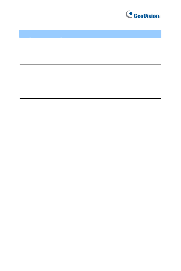
No. Name Function
10
PTZ Control
Panel
Enables the PTZ Control Panel or the Visual PTZ.
Note this function is supported by PTZ Camera
and PT Camera, and only partially supported by
GV-IP Cameras with motorized varifocal lens.
11 I/O Control
Enables the I/O Control Panel and Visual
Automation. Note this function is not available in
Mini Fixed Dome, Mini Fixed Rugged Dome,
Cube Camera, Advanced Cube Camera and
Target Series.
12 LED Control
Click to turn the Alarm LED on and/or adjust the
brightness sensitivity. Note this function is only
available for Advanced Cube Camera.
13
Alarm
Speaker
Click to sound the alarm and/or adjust its volume.
To sound the alarm upon motion or tampering
events, see Speaker section, Administrator Mode
Chapter, GV-IPCAM Firmware Manual. Note this
function is only available for Advanced Cube
Camera.

111
Chapter 10 Upgrading System
Firmware
GeoVision periodically releases updated firmware on the website. The new
firmware can be simply loaded into the GV-IPCAM by using the Web
interface or IP Device Utility.
Before you start
If you use the IP Device Utility for firmware upgrade, the computer
used to upgrade firmware must be under the same network of the
camera.
Stop monitoring of the camera.
Stop all remote connections, such as GV-VMS.
While the firmware is being updated, the power supply must not be
interrupted.
WARNING: The interruption of power supply during updating causes
not only update failures but also damages to the camera. In this case,
please contact your sales representative and send your device back to
GeoVision for repair.
Do not turn the power off within 10 minutes after the firmware is
updated.
112
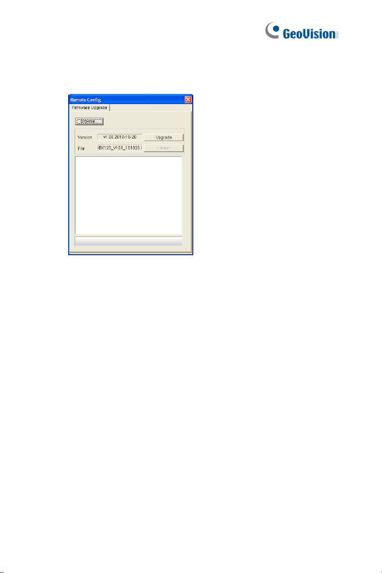
1. In the Live View window, click the Show System Menu button and
select Remote Config. This dialog box appears.
Figure 10-1
2. Click the Browse button to locate the firmware file (.img) saved at
your local computer.
3. Click the Upgrade button to start the upgrade.