Loading ...
Loading ...
Loading ...
27
EE
EN
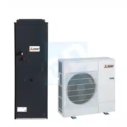
[Output pattern B] Errors detected by unit other than indoor unit (outdoor unit, etc.)
IR wireless remote controller
Wired remote controller
RF thermostat
Symptom Remark
Beeper sounds/OPERATION
INDICATORlampashes
(Number of times)
Check code
1 E9 Indoor/outdoor unit communication error (Transmitting error)
(Outdoor unit)
2 UP Compressor overcurrent interruption
3 U3, U4 Open/short of outdoor unit thermistors
4 UF Compressor overcurrent interruption (When compressor locked)
5 U2 Abnormalhighdischargingtemperature/49Cworked/insucientrefriger-
ant
6 U1, Ud Abnormal high pressure (63H worked)/ Overheating safeguard operation
7 U5 Abnormal temperature of heat sink
8 U8 Outdoor unit fan protection stop
9 U6 Compressor overcurrent interruption/Abnormal of power module
10 U7 Abnormality of super heat due to low discharge temperature
11 U9, UH Abnormality such as overvoltage or voltage shortage and abnormal and
synchronous signal to main circuit/Current sensor error
12 – –
13 – –
14 Others Other errors (Refer to the technical manual for the outdoor unit.)
*1Ifthebeeperdoesnotsoundagainaftertheinitialtwobeepstocon�rmtheself-checkstartsignalwasreceivedandthe
OPERATION INDICATOR lamp does not come on, there are no error records.
*2Ifthebeepersoundsthreetimescontinuously“beep,beep,beep(0.4+0.4+0.4sec.)”aftertheinitialtwobeepstocon�rmthe
self-checkstartsignalwasreceived,thespeci�edrefrigerantaddressisincorrect.
• On IR wireless remote controller
The continuous buzzer sounds from receiving section of indoor unit.
Blink of operation lamp
• On wired remote controller
Check code displayed on the LCD.
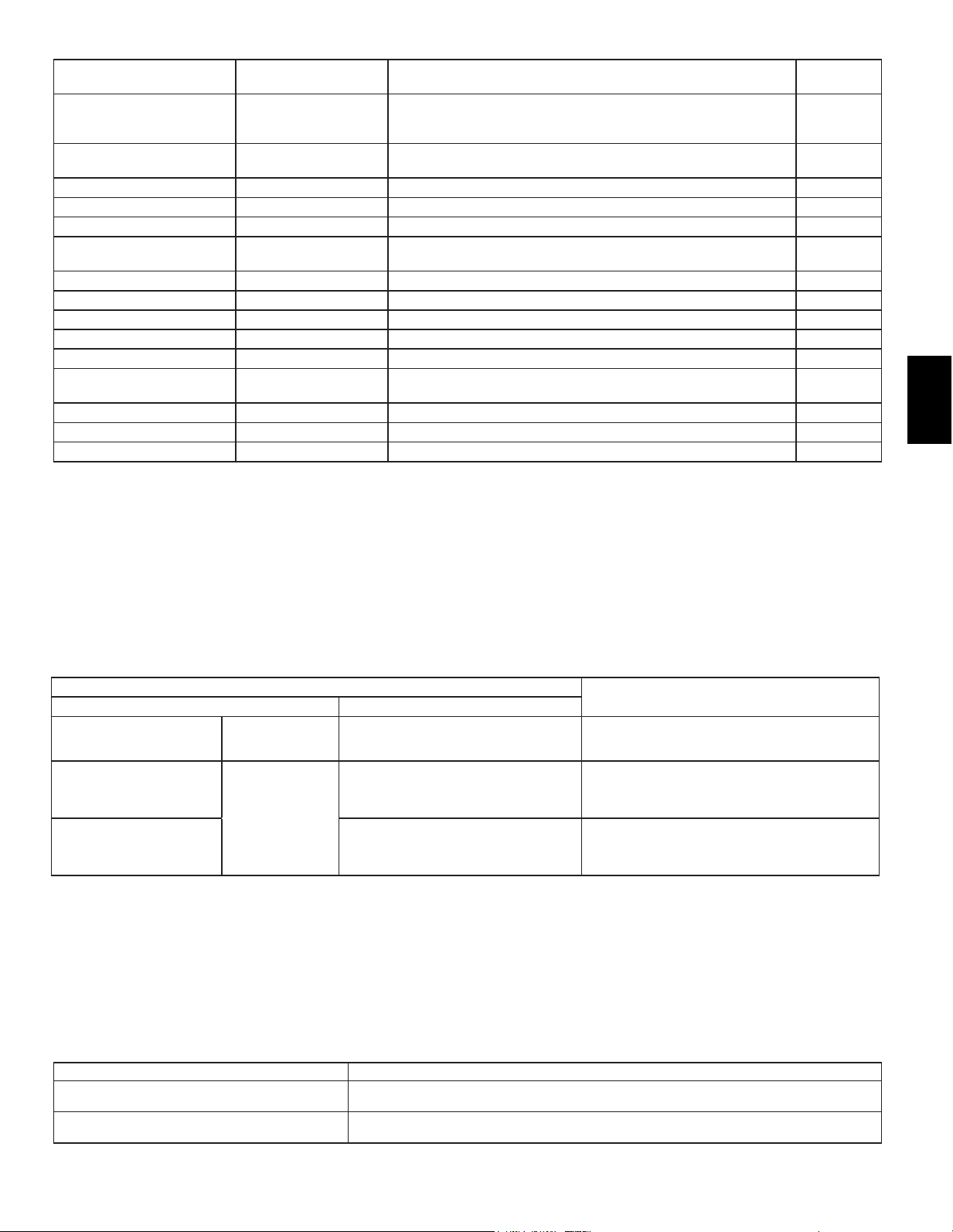
• If the unit cannot be operated properly after the above test run has been performed, refer to the following table to remove the cause.
Symptom
Cause
Wired remote controller LED 1, 2 (PCB in outdoor unit)
PLEASE WAIT
For about 2 minutes
following power-on
After LED 1, 2 are lighted, LED 2 is turned
o,thenonlyLED1islighted.(Correct
operation)
• For about 2 minutes after power-on, operation of the
remote controller is not possible due to system start-up.
(Correct operation)
PLEASEWAIT→Errorcode
After about 2 minutes
has expired
following power-on
OnlyLED1islighted.→LED1,2blink.
• Connector for the outdoor unit’s protection device is not
connected.
• Reverse or open phase wiring for the outdoor unit’s power
terminal block (L1, L2, L3)
Display messages do not appear
even when operation switch is
turned ON (operation lamp does
not light up).
OnlyLED1islighted.→LED1,2blinks
twice, LED 2 blinks once.
• Incorrect wiring between indoor and outdoor units
(incorrect polarity of S1, S2, S3)
• Remote controller wire short
On the IR wireless remote controller with conditions above, following phenomena takes place.
• No signals from the remote controller are accepted.
• OPE lamp is blinking.
• The buzzer makes a short ping sound.
Note:
Operation is not possible for about 30 seconds after cancellation of function selection. (Correct operation)
For description of each LED (LED1, 2, 3) provided on the indoor controller, refer to the following table.
LED 1 (power for microcomputer) Indicates whether control power is supplied. Make sure that this LED is always lit.
LED 2 (power for remote controller)
Indicates whether power is supplied to the remote controller. This LED lights only in the case of
the indoor unit which is connected to the outdoor unit refrigerant address “0”.
LED 3 (communication between indoor and outdoor units)
Indicates state of communication between the indoor and outdoor units. Make sure that this LED is
always blinking.
Loading ...
Loading ...
Loading ...