Loading ...
Loading ...
Loading ...
En-3
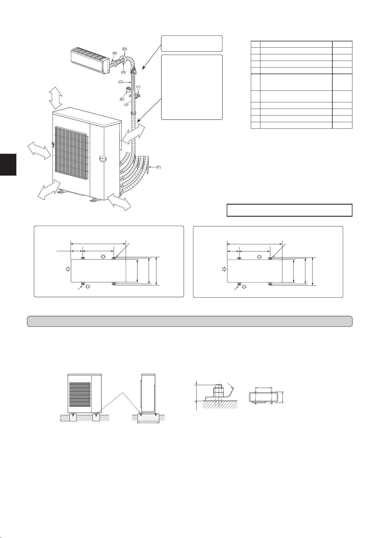
1-5. INSTALLATION DIAGRAM
Units should be installed by licensed contractor according to
local code requirements.
Afterthe leak test, apply insulat-
ing material tightly so that there
is no gap.
When the piping is to be attached to
a wall containing metals (tin plated)
or metal netting, use a chemically
treated wooden piece 25/32 in. (20
mm)or thicker between the wall
and the piping or wrap 7 to 8 turns
of insulation vinyl tape around
the piping.
To use existing piping, perform
COOL operation for 30 minutes
and pump down before removing
theoldairconditioner.Remakeare
according to the dimension for new
refrigerant.
PARTS TO BE PROVIDED AT YOUR SITE
(A) Power supply cord* 1
(B) Indoor/outdoor unit connecting wire* 1
(C) Extension pipe 1
(D) Wallholecover 1
(E) Piping tape 1
(F)
Extensiondrainhose(orsoftPVC
hose, 19/32 in. (15 mm) inner
diameterorhardPVCpipeVP16)
1
(G) Refrigeration oil
Little
amount
(H) Putty 1
(I) Pipexingband 2 to 7
(J) Fixing screw for (I) 2 to 7
(K) Wallholesleeve 1
* Note:
Place indoor/outdoorunit connecting wire (B) and
power supply cord (A) at least 3 ft. (1 m) away from
theTVantennawire.
The“Q’ty”for(B)to(K)intheabovetableisquantity
to be used per indoor unit.
More than
3-15/16 in.
(100 mm)
Open as a rule
More than 19-11/16
in. (500 mm) if the
front and both sides
are open
More than 3-15/16 in. (100 mm)
More than 7-7/8 in. (200 mm)
if there are obstacles to both
sides
Open as a rule
More than 19-11/16 in. (500 mm) if the
back,bothsidesandtopareopen
More than 13-25/32 in.
(350 mm)
Outdoor unit installation
Air inlet
Air outlet
2-U-shape notched holes
(BaseboltM10)
Unit : inch
2-1. INSTALLING THE UNIT
Fix here with
M10 bolts.
Makethesetting
depth deeper.
Makewithwider.
Anchor leg
31/32 (25) or less
Anchor bolt length
Anchor bolt pitch
(Unit: inch (mm))
• Besuretoxtheunit’slegswithboltswheninstallingit.
• Besuretoinstalltheunitrmlytoensurethatitdoesnotfallbyanearthquakeoragust.
• Refertothegureintherightforconcretefoundation.
• IncaseofMXZ-2C20NAHZ2,MXZ-3C24/30NAHZ2,donotusethedrainsocketandthedraincaps.
• IncaseofMXZ-5C42NA2,donotusethedrainsocketandthedraincapsinthecoldregion.Drainmayfreezeanditmakesthefanstop.
23-5/8
(600)
14-9/16
(370)
Outdoor unit installation
37-13/32
23-5/8
6-7/8
2 - (15/32 × 1-31/32)
ovalholes(BaseboltM10)
Air inlet
13
14-9/16
16-13/32
Air inlet
Air outlet
2-U-shape notched holes
(BaseboltM10)
Unit : mm
950
600175
2 - 12 × 36
ovalholes(BaseboltM10)
Air inlet
330
370
417
2. OUTDOOR UNIT INSTALLATION
BH79A240H02_en.indd 3 2016/03/24 14:46:28
Loading ...
Loading ...
Loading ...