Loading ...
Loading ...
Loading ...

LABPS3003SM
V. 03 – 27/10/2017 4 ©Velleman nv
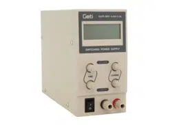
4. Overview
Refer to the illustrations on page 2 of this manual.
1
amp-display (LED): indicates the output current.
6
voltage fine-tuning knob: rotary knob for the
fine-tuning of the output voltage.
2
volt-display (LED): indicates the output voltage.
7/8
constant current/voltage indicator
3
current fine-tuning knob: rotary knob for the
fine-tuning of the current-limiting point.
9
power switch
4
current adjustment knob: rotary knob for the
adjustment of the current-limiting point.
10
output terminal (+): used for the connection of
the load's positive terminal.
5
voltage adjustment knob: rotary knob for the
adjustment of the output voltage.
11
output terminal (-): used for the connection of
the load's negative terminal.
5. Operation
5.1 Introduction
The device is a highly accurate, DC-regulated power supply with an adjustable output. This output can be used
for constant voltage (C.V.) and constant current (C.C.).
The output voltage can be adjusted between 0 V and 30V when the device is in the constant voltage mode or
C.V.-mode. The current-limiting point (max. ± 3 A) can also be set arbitrarily in this mode.
The output current can be adjusted continuously between 0 and 3 A in the constant current mode.
The output current and voltage are indicated through LED displays.
5.2 Using the device as a C.V. source
1. Switch on the device.
2. Turn the current adjustment knob fully clockwise to the maximum.
3. Turn the voltage adjustment knob to obtain a voltage that is close to the desired value. Use the fine-tune
knob if desired (where applicable). The C.V. indicator lights on the display.
5.3 Using the current-limiting adjustment in C.V. mode
1. Switch on the device.
2. Turn both the current adjustment knobs fully anticlockwise to the minimum, and the voltage adjustment
knobs fully clockwise to the maximum.
3. Short-circuit the output terminals by interconnecting them with the appropriate cable (60 V/16 A DC cable).
4. Turn the current adjustment knob to the required current-limiting value. Use the fine-tune knob if desired
(where applicable). The C.C. indicator lights on the display.
5. Remove the short-circuit cable from both output terminals.
6. Turn the voltage adjustment knob to the required value. Use the fine-tune knob if desired (where
applicable). The C.V. indicator lights up on the display.
7. Connect the load to the output terminals. If the current exceeds the current-limiting point, the C.C.
indicator lights up on the display.
5.4 Connecting the Load
Connect the load.
You can read the output current and the output voltage from the display as soon as the device has been
switched on.
The C.V. indicator is lit if the device is in the C.V.-mode.
The C.V. LED is off and the C.C. LED will light if the Amp display indicates a value that exceeds the installed
value. When this happens, the device will automatically go into current-limiting mode. Install a load that
will allow the device to function normally.
Loading ...
Loading ...
Loading ...