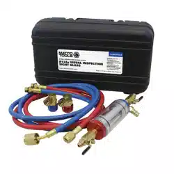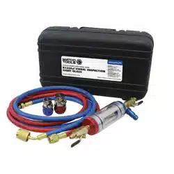
AIR CONDITIONING SYSTEM MANIFOLD
WITH SIGHT GLASS
MODEL NO: VSAC002.V2
Thank you for purchasing a Sealey product. Manufactured to a high standard, this product will, if used according to these
instructions, and properly maintained, give you years of trouble free performance.
IMPORTANT: PLEASE READ THESE INSTRUCTIONS CAREFULLY. NOTE THE SAFE OPERATIONAL REQUIREMENTS, WARNINGS & CAUTIONS. USE
THE PRODUCT CORRECTLY AND WITH CARE FOR THE PURPOSE FOR WHICH IT IS INTENDED. FAILURE TO DO SO MAY CAUSE DAMAGE AND/OR
PERSONAL INJURY AND WILL INVALIDATE THE WARRANTY. KEEP THESE INSTRUCTIONS SAFE FOR FUTURE USE.
1. SAFETY
WARNING! Ensure that Health and Safety, local authority and general workshop practice regulations are adhered to when using
tools.
WARNING! Any work carried out on the A/C system should only be performed by an Air Conditioning service technician
following the vehicle manufacturer’s service instructions or a proprietary manual to establish the current procedure and
data.
8 DO NOT use manifold if damaged.
9 Dispose of refrigerants according to local authority guidelines.
8 DO NOT Allow refrigerant to vent to atmosphere.
9 Maintain the manifold in a good condition for prolonged life and safe use.
9 Wear suitable eye protection. A full range of personal safety equipment is available from your Sealey stockist.
9 Wear suitable protective clothing and gloves when working with refrigerant.
9 Wear suitable clothing to avoid snagging. DO NOT wear jewellery and tie back long hair.
9 Account for all tools and parts being used and DO NOT leave them on or near the engine.
9 On completion of work, put the equipment back and store in a cool, dry, childproof location.
WARNING: The warnings, cautions and instructions discussed in this instruction manual cannot cover all possible
conditions and situations that may occur. It must be understood that common sense and caution are factors which cannot
be built into this product, but must be applied by the operator.
IMPORTANT: These instructions are provided as a guide only. Always refer to the vehicle manufacturer’s service instructions,
or a proprietary manual, to establish the current procedure and data.
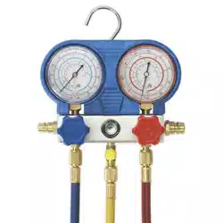
2. INTRODUCTION
Designed for refrigerant testing, charging and evacuation. Can be used on automotive, commercial and domestic A/C and domestic refrigeration
systems. Gauges marked for R134a and R12 pressure reading. Colour-coding on gauges, valves and hoses for easy operation. Features 2-way
manifold and sight glass for monitoring refrigerant ow. Quick couplings included and hanging hook.
3. SPECIFICATION
Model No:.........................................................VSAC002.V2
Application(s): ..................................................... R134a, R12
Hose Length:............................................................1550mm
4. OPERATION
WARNING! Disconnect hoses with extreme caution! Pressurised
refrigerant may be present in hoses. Never direct hoses toward
yourself or any other persons.
4.1. CONNECTING QUICK COUPLERS
4.2. Quick couplers are provided to access the vehicle’s service ports.
The quick coupler should be in the closed position before connecting
to the male tting on the vehicle.
4.2.1. To close, turn the handle fully anti-clockwise. Connect the blue and red
hoses to the corresponding couplers and then to the corresponding side
of the manifold.
4.2.2. Place the quick couplers on the male ttings on the vehicle.
4.2.3. Push in on the handle of the quick coupler with your thumb, while pulling
up on the sleeve until it bottoms on the male tting and then release.
Check to see if it is correctly seated by pulling up on the quick coupler.
4.2.4. Make sure the hand-wheels on the manifold are closed (fully clock-wise)
and turn the quick coupling knob fully anti-clockwise, to open the valve.
4.3. DIAGNOSING SYSTEM OPERATION
4.3.1. Ensure both hand-wheels are closed (turn fully clockwise) and connect
the blue low side hose to the A/C system’s low pressure side service port.
Refer to
instructions
Wear eye
protection
Wear protective
gloves
Wear safety
footwear
Wear protective
clothing
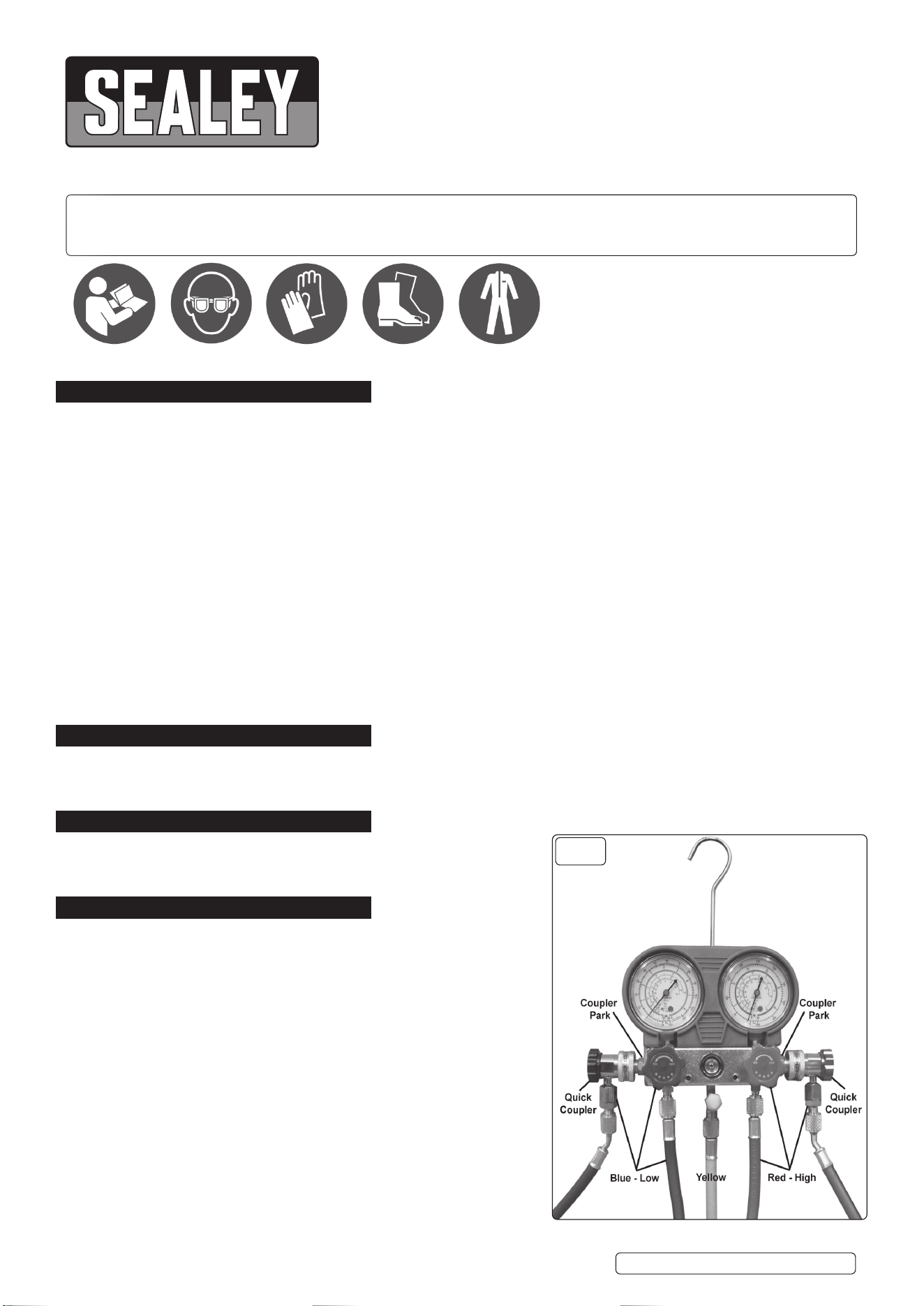
g.1
Original Language Version
© Jack Sealey Limited
VSAC002.V2 Issue 3 (H,2) 05/05/23
Connect the red high side hose to the A/C system’s high pressure side service port. (Already done in section 4.1).
4.3.2. With the manifold hand-wheels closed (fully clockwise), read the pressures on each gauge.
4.3.3. Compare these pressures and temperatures to the A/C system manufacturer’s specications for proper operation.
4.3.4. If the system is within the correct operating guidelines, disconnect the manifold hoses from the system (close both hand wheels and
couplers before removing). If repairs are necessary, follow the steps for recovering, evacuating and recharging the system.
4.4. RECOVERING REFRIGERANT
Note: Refrigerant should not be exhausted to the atmosphere.
4.4.1. Ensure the blue low side hose is connected to the A/C system’s low side service port, the red high side hose is connected to the
A/C system’s high side service port and the yellow centre hose connects to the inlet of the recovery unit. Set up as in g.1.
4.4.2. Follow the instructions provided with the recovery unit for proper recovery of refrigerant from the A/C system.
4.5. EVACUATING AND CHARGING A REFRIGERANT SYSTEM
4.5.1. See section 4.1 (Connecting quick couplers) before proceeding. Connect the blue low side hose to the A/C system’s low side
service port. Connect the red high side hose to the A/C system’s high side service port.
4.5.2. Check the manifold gauge pressure reading to be sure the A/C system has been recovered properly. If not, follow steps under
Section 4.3 (Recovering Refrigerant). If it has, connect the centre yellow charging hose to a vacuum pump. Set up as in g.1.
4.5.3. Open the high and low side hand-wheels (fully anti-clockwise) and start the vacuum pump.
4.5.4. After evacuating the system according to the manufacturer’s specications, close both the high and low side hand-wheels and turn
o the vacuum pump.
4.5.5. Disconnect the yellow hose from the vacuum pump and connect it to the refrigerant supply.
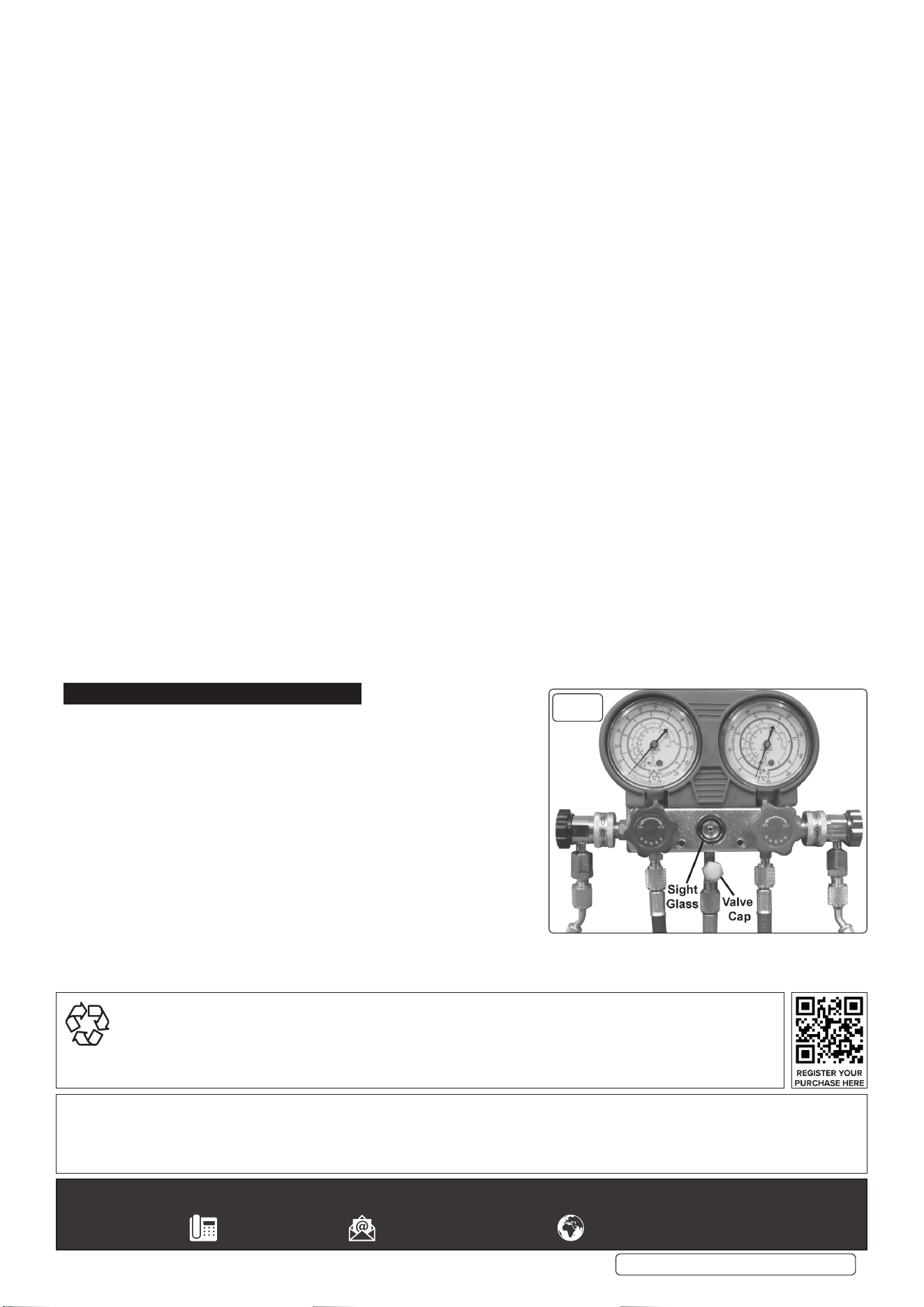
4.5.6. Slightly open the refrigerant supply valve. Remove the valve cap (g.2) and purge air from the yellow charging hose at the manifold
according to manufacturer’s recommendations, then close the supply valve.
4.5.7. You can now charge the A/C system according to the manufacturer’s specications.
• If the system specications call for CHARGING ON THE HIGH SIDE, close the manifold’s blue low side hand-wheel, open
the refrigerant supply valve and open the manifold’s red high side hand-wheel. To nd out when to cease adding refrigerant keep
an eye on the sight glass (g.2), when bubbles stop appearing, close the manifold’s red high side hand-wheel and close the refrigerant
supply valve.
• If the system specications call for CHARGING ON THE LOW SIDE, close the manifold’s red high side hand-wheel, open
the refrigerant supply valve and open the manifold’s blue low side hand-wheel. To nd out when to cease adding refrigerant keep
an eye on the sight glass (g.2), when bubbles stop appearing, close the manifold’s blue low side hand-wheel and close the refrigerant
supply valve.
4.5.8. When you have charged the system, close both manifold hand-wheels. Let the compressor run and check the manifold’s gauge
pressure readings to be sure the system is operating properly. If it is not, adjust the system as necessary. To disconnect
the manifold when the system is operating correctly, rst close the high side coupler valve, then disconnect the red high
quick coupler from the A/C system.
4.5.9. Restart the A/C system, then open both manifold hand-wheels. Refrigerant from both hoses will be drawn quickly into the A/C
system through the blue low side hose.
4.5.10. When both gauges show the lowest operating pressure recommended by the manufacturer, close the low side valve and turn o
the A/C system.
4.5.11. Close the low side coupler valve and disconnect the low side hose from the A/C system.
5. MAINTENANCE
5.1. Keep the manifold in good working order.
5.2. Periodically replace O-rings and valve seats.
5.3. Be sure to lubricate O-rings with high vacuum grease.
5.4. Generally keep the manifold clean from dirt and grime to improve product
life.
g.2
VSAC002.V2 Issue 3 (H,2) 05/05/23
Original Language Version
© Jack Sealey Limited
Sealey Group, Kempson Way, Suffolk Business Park, Bury St Edmunds, Suffolk. IP32 7AR
01284 757500 sales@sealey.co.uk www.sealey.co.uk
ENVIRONMENT PROTECTION
Recycle unwanted materials instead of disposing of them as waste. All tools, accessories and packaging should be sorted,
taken to a recycling centre and disposed of in a manner which is compatible with the environment. When the product
becomes completely unserviceable and requires disposal, drain any fluids (if applicable) into approved containers and
dispose of the product and fluids according to local regulations.
Note: It is our policy to continually improve products and as such we reserve the right to alter data, specifications and component parts without prior
notice.
Important: No Liability is accepted for incorrect use of this product.
Warranty: Guarantee is 12 months from purchase date, proof of which is required for any claim.