270L BELT DRIVE AIR COMPRESSOR 2 X 3HP
WITH CAST CYLINDERS
MODEL NO: SAC1276B, SAC2276B.V2
Refer to
Instructions
Warning:
Electricity
Warning:
Hot Surface
Warning:
Automatic
Start-up
Wear ear
protection
Thank you for purchasing a Sealey product. Manufactured to a high standard, this product will, if used according to these instructions,
and properly maintained, give you years of trouble free performance.
IMPORTANT: PLEASE READ THESE INSTRUCTIONS CAREFULLY. NOTE THE SAFE OPERATIONAL REQUIREMENTS, WARNINGS & CAUTIONS. USE THE
PRODUCT CORRECTLY AND WITH CARE FOR THE PURPOSE FOR WHICH IT IS INTENDED. FAILURE TO DO SO MAY CAUSE DAMAGE AND/OR PERSONAL
INJURY AND WILL INVALIDATE THE WARRANTY. KEEP THESE INSTRUCTIONS SAFE FOR FUTURE USE.
1. SAFETY
1.1. ELECTRICAL SAFETY
WARNING! It is the user’s responsibility to check the following:
9 Ensure that any faulty item is repaired or replaced immediately by a qualied electrician.
9 Check all electrical equipment and appliances to ensure that they are safe before using.
9 Inspect power supply leads, plugs and all electrical connections for wear and damage.
9 Sealey recommend that an RCD (Residual Current Device) is used with all electrical products.
9 If the product is used for business, it must be maintained in a safe condition and routinely PAT (Portable Appliance Test) tested.
9 Ensure that the insulation on all cables and on the appliance is safe before connecting it to the power supply.
9 Ensure that the voltage rating on the appliance suits the power supply to be used and that the plug is tted with the correct fuse - see
fuse rating in these instructions.
8 DO NOT pull or carry the appliance by the power cable.
8 DO NOT pull the plug from the socket by the cable. Remove the plug from the socket by maintaining a rm grip on the plug.
8 DO NOT use worn or damaged cables, plugs or connectors.
9 A 32A supply is required. We recommend that a 32A industrial round pin plug should be tted and connected to a 32A supply having a
Type C breaker. If in doubt, you must contact a qualied electrician to ensure that a suitably rated supply is available.
Note: The use of extension leads to connect these compressors to the mains is not recommended as the resulting voltage drop reduces
motor, and therefore pump performance.
1.2. GENERAL SAFETY
WARNING! Compressor must only be serviced by an authorised agent.
8 DO NOT tamper with, or attempt to adjust, pressure switch or safety valve.
9 Familiarise yourself with the application and limitations of the compressor.
9 Ensure the compressor is in good order and condition before use.
9 If in any doubt do not use the unit and contact an electrician/service agent.
9 Before moving/maintaining the compressor ensure it is unplugged from the mains supply and that the air tank pressure has been vented.
9 Maintain the compressor in good condition and replace any damaged or worn parts. Use genuine parts only. Unauthorised parts may be
dangerous and will invalidate your warranty.
9 Read the instructions relating to any accessory to be used with this compressor.
9 Ensure the safe working pressure of any air appliance used exceeds compressors output pressure. If using a spray gun, check that the
area selected for spraying is provided with an air change system/ventilation.
9 Ensure the air supply valve is turned off before disconnecting the air supply hose.
9 Use the compressor in a well ventilated area and ensure it is placed on a rm surface.
9 Keep tools and other items away from the compressor when it is in use, and keep area clean and clear of unnecessary items.
9 Ensure the air hose is not tangled, twisted or pinched.
9 Keep children and unauthorised persons away from the working area.
8 DO NOT disassemble compressor for any reason. The unit must be checked by qualied personnel only.
8 DO NOT use the compressor outdoors, or in damp, or wet, locations.
8 DO NOT operate within the vicinity of ammable liquids, gases or solids.
8 DO NOT touch compressor cylinder, cylinder head, or pipe from head to tank as these may be hot.
8 DO NOT use this product to perform a task for which it has not been designed.
8 DO NOT deface the certication plate attached to the compressor tank.
8 DO NOT cover the compressor or restrict air ow around the unit whilst operating.
▲ DANGER! DO NOT direct the output jet of air towards people or animals.
8 DO NOT operate the compressor without an air lter.
8 DO NOT allow anyone to operate the compressor unless they have received full instructions.
WARNING! The air tank is a pressure vessel and the following safety measures apply:
8 DO NOT tamper with the safety valve, DO NOT modify or alter the tank in any way and DO NOT strap anything to the tank.
8 DO NOT subject the tank to impact, vibration or to heat, and DO NOT allow contact with abrasives or corrosives.
9 Drain condensation from tank and inspect inside walls for corrosion as per the maintenance schedule and have a detailed tank inspection
carried out annually. The tank shell must not fall below the certified thickness at any point.
WARNING! If an electrical fuse blows, ensure it is replaced with an identical fuse type and rating.
9 When not in use for a prolonged period, and if possible, store the compressor carefully in a safe, dry, childproof location.
9 When the compressor is not in use, it should be switched off, isolated from the mains supply and the air drained from the tank.
SAC1276B, SAC2276B Issue 5 (ALL) 18/08/23
Original Language Version
© Jack Sealey Limited
2. INTRODUCTION
High output unit suitable for the professional workshop. Fitted with two genuine 3hp motors and two identical pumps. Twin capacitors
and a centrifugal switch aid trouble-free starting on a 230V 32A supply. This unit is supplied with a control box featuring a stepped start
up to prevent high Amp spikes. Pumps feature heavy-duty full cast cylinders, capped by alloy heads for improved heat dissipation and
long-life. Heavy-duty drive guards protect belt and ywheel that is designed to force air over the pump to aid cooling.
3. SPECIFICATION
Model No: SAC1276B SAC2276B
Air Displacement cfm(L/min): 26.8(759) 30(850)
Maximum Free Air Delivery
cfm(L/min):
19.4(549) 21.8(618)
Maximum Pressure: 145psi(10bar) 145psi(10bar)
Minimum Rated Supply: 32A 32A
Motor Output: 3hp (x2) 3hp (x2)
Outlet: 3/4"BSP Female Tap 3/4"BSP Female Tap
Phase: 1ph 1ph
Plug Type: Bare Wire Bare Wire
Receiver Capacity: 270L 270L
Size (W x D x H): 1550 x 540 x 935mm 1550 x 540 x 960mm
Speed: 1636rpm 1280rpm
Supply: 230V/32A 230V/32A
4. PREPARATION
4.1. Remove compressor from packaging. If anything is found to be missing or damaged, contact your supplier.
4.2. Check the mains voltage corresponds with the voltage shown on the compressor data plate.
4.3. A qualied electrician should t a suitable 3 pin industrial plug.
FIG.1 FIG.2 FIG.3
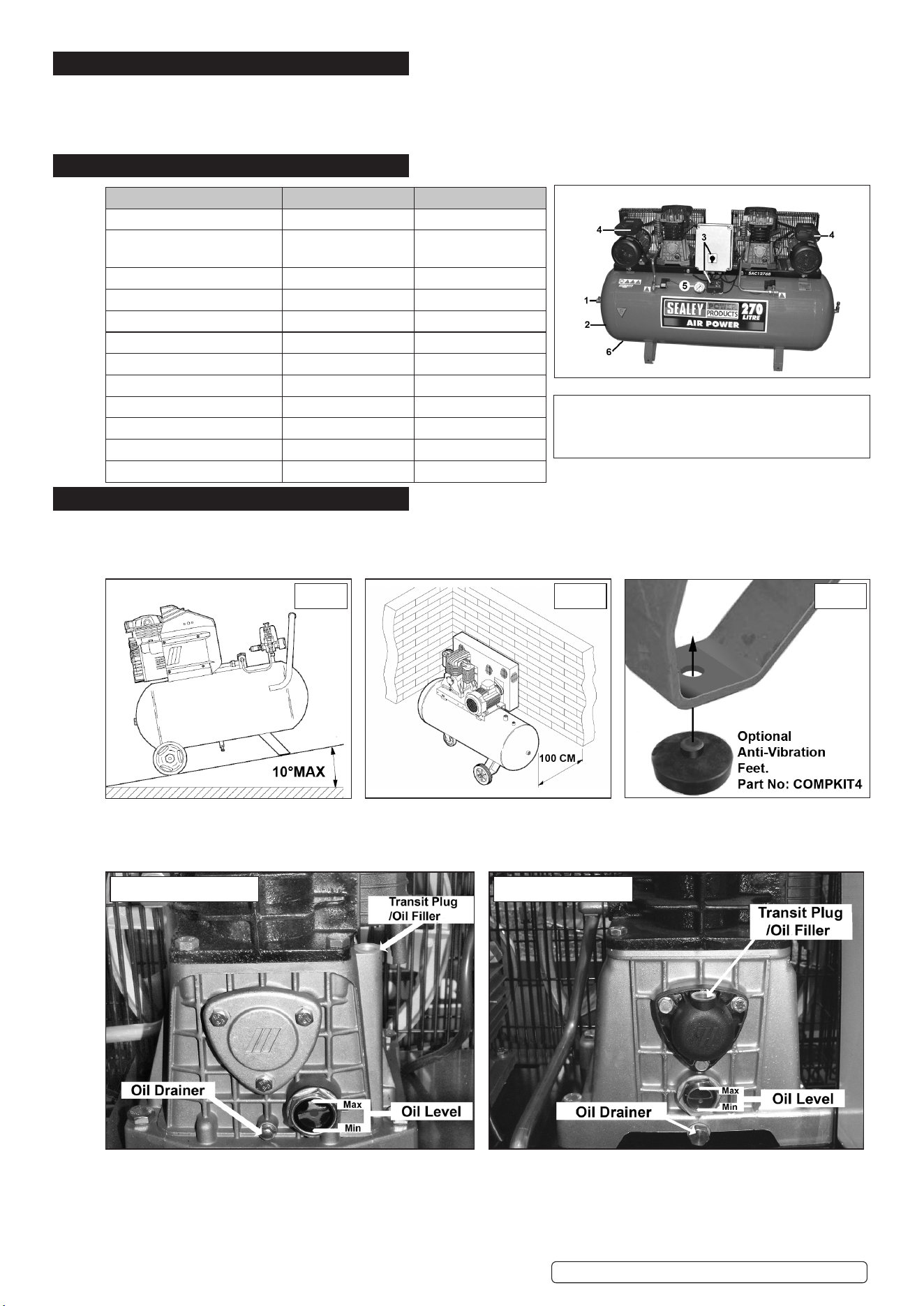
4.4. Position the compressor on a at surface with a maximum incline of 10° (FIG.1). DO NOT lift the compressor with hooks or ropes.
4.5. Position in a well ventilated area, at least 100cm from any wall (FIG.2). Keep the compressor away from atmospheric pollution/hazards.
4.6. Ensure the compressor is secure and cannot fall. Optional anti-vibration feet can be purchased from your Sealey stockist (FIG 3).
FIG.4 - SAC1276B FIG.5 - SAC2276B
4.7. Remove the plastic transit plug from the oil ller hole (FIG.4 & FIG.5) and replace with the ller/breather plug.
4.8. Check the oil level by observing the sight glass (FIG.4 & FIG 5). Top up with synthetic oil so the oil level is at the maximum mark.
8 DO NOT use mineral oil in these compressors.
8 DO NOT overll.
SAC1276B illustrated (SAC2276B differs slightly)
1. Direct Compressed Air Outlet 2. Tank
3. On/Off Switches 4. Reset
5. Pressure Gauge 6. Condensate Drain Tap
SAC1276B, SAC2276B Issue 5 (ALL) 18/08/23
Original Language Version
© Jack Sealey Limited
5. OPERATION
WARNING! Ensure that you have read, understood and apply Section 1 Safety Instructions.
NOTE: Take care when selecting tools for use with the compressor. Air tool manufacturers normally express the volume of air required
to operate a tool in cubic feet per minute (cfm). This refers to free air delivered by the compressor (‘air out’) which varies according to
the pressure setting. Do not confuse this with the compressor displacement which is the air taken in by the compressor (‘air in’). ‘Air out’
is always less than ‘air in’ due to losses within the compressor.
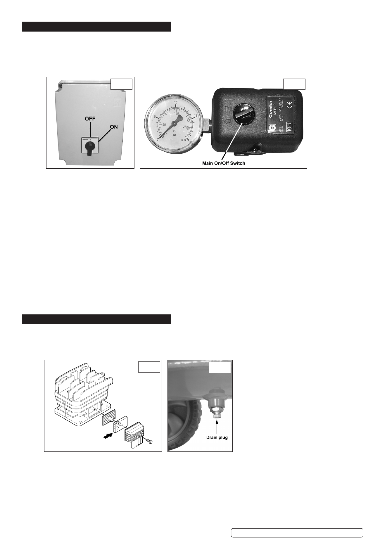
STARTING THE COMPRESSOR
5.1. Check both switches (on the control box and the pressure switch housing) are in the OFF (0) position. Plug into the main electrical
supply. To turn the compressor on, turn the switch on the control box (g.6) to the '1' position and then turn the switch on the pressure
switch housing (g.7) clockwise to position 'I'.
5.2. The first motor/pump will start up followed a few seconds later by the second motor/pump.
5.3. When starting the compressor for the first time, leave it running with no air tools connected to the air outlet. Make sure that the pressure in
the tank rises and that the compressor stops automatically when the maximum pressure value allowed - written on the plate and shown on
the gauge (fig.7) - is achieved. The compressor will now operate automatically. The pressure switch stops the motor when the maximum
tank pressure is reached and restarts it when the pressure falls below the minimum threshold - approx. 2bar (29psi) less than the maximum
pressure.4.3. To stop the compressor, first turn the main switch (fig.7) to the '0' position and then turn the switch on the control box (fig.6)
to the '0' position. The compressed air inside the compressor heads will flow out, making the restart easier and preventing the motors from
being damaged. DO NOT, other than in an emergency, stop the compressor by switching off at the mains, or by pulling the plug out, as the
pressure relief will not then operate and motor damage may result upon restart.
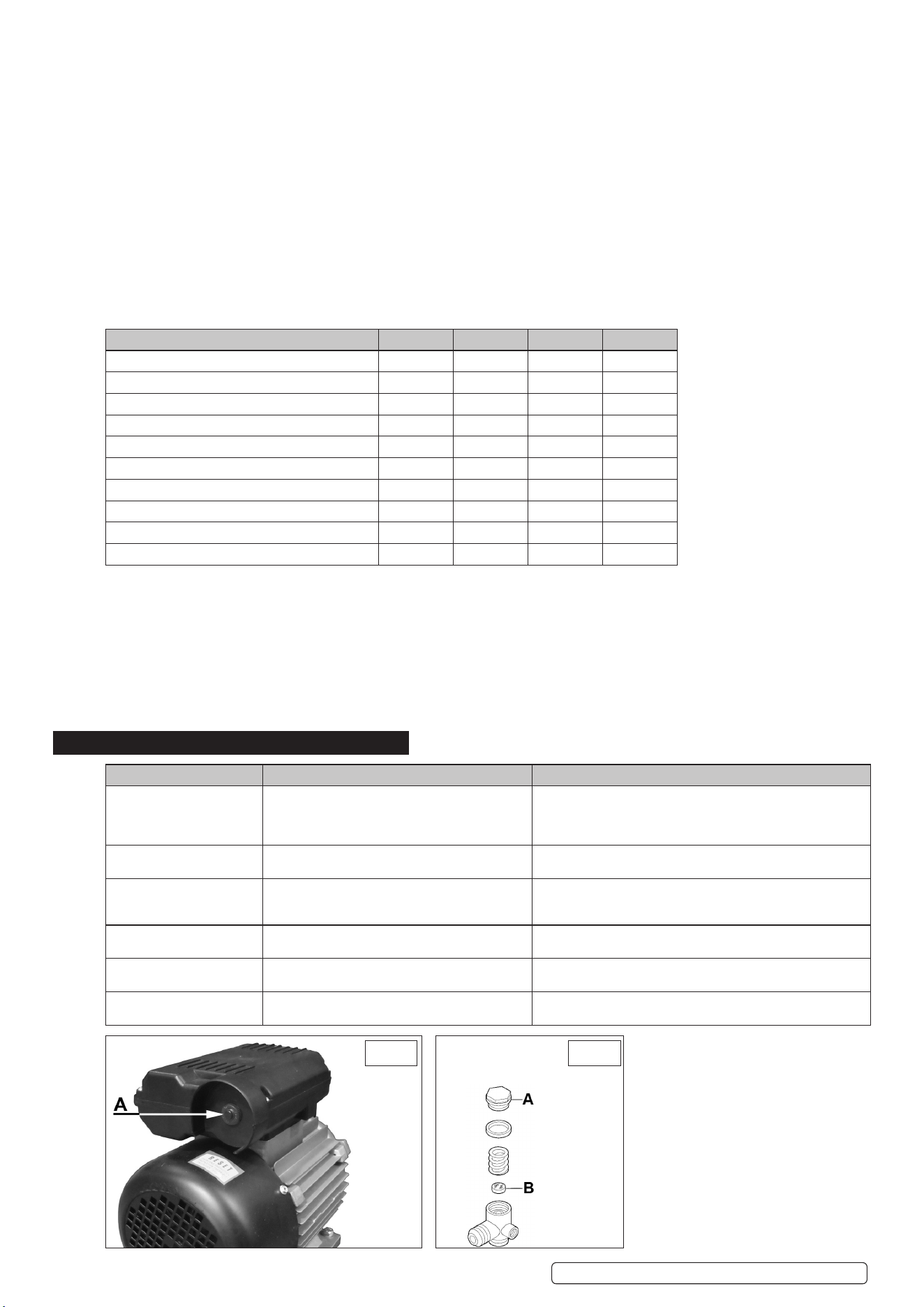
5.4. The motors of the compressor are fitted with a thermal breaker located in the housing on top of the motors. The manual resetting buttons
are located in the end of the housings as shown in fig.10A. When the individual breaker is tripped, wait for a few minutes and then press
the reset button.
NOTE:
A) If the motor does not cut in and out, but runs continuously when using an air appliance, the capacity of the compressor may be too small
for the equipment or tool.
B) The gauge (fig.7) indicates the pressure inside the main tank, NOT the pressure supplied to the air equipment. Should the pressure in
the main tank exceed the pre-set switch maximum, the safety valve will activate.
WARNING! For this reason DO NOT tamper with, or adjust, the switch or safety valve.
6. MAINTENANCE
In order to keep the compressor in good working condition, periodic maintenance is essential.
IMPORTANT: Failure to carry out maintenance tasks may invalidate the warranty on your compressor.
WARNING! Before performing any maintenance operation, switch off the compressor, disconnect from electricity supply and release all
air from the tank (except for 5.3.a)
FIG.8
FIG.9
6.1. OPERATIONS TO BE CARRIED OUT AFTER THE FIRST 50 WORKING HOURS:
a) Check that all bolts/nuts are tight, particularly those retaining the crankcase and cylinder head.
b) Replace the lubricating oil - see para 5.5.a.
6.2. OPERATIONS TO BE CARRIED OUT WEEKLY:
a) Drain condensation by opening the valve located under the tank (g.9). Place a container under the valve and open the valve by
turning anti-clockwise.
WARNING! Take care if there is still pressure inside the cylinder as water could ow out with coinsiderable force.
Recommended pressure 1 - 2bar max.
b) Check oil level and, if necessary, top up.
6.3. OPERATIONS TO BE CARRIED OUT EVERY 50 HOURS:
FIG.6 FIG.7
SAC1276B, SAC2276B Issue 5 (ALL) 18/08/23
Original Language Version
© Jack Sealey Limited
(or more frequently, if the compressor operates in a very dusty atmosphere):
a)Remove the air lter element (g.8). Using stored air from the compressor's tank, clean the lter with compressed air. (Wear eye
protection and DO NOT direct air towards the body or hands). DO NOT operate the compressor without the lter as foreign bodies or
dust could seriously damage the pump. Replace the lter element and air lter housing. b) Check for oil leaks.
6.4. OPERATIONS TO BE CARRIED OUT EVERY 100 HOURS:
a) Check the automatic cut-out at max. pressure and the automatic cut-in at 2bar below.
6.5. OPERATIONS TO BE CARRIED OUT EVERY 400 HOURS:
a)Replace the lubricating oil. For oil specications see 5.7. Remove the ller/breather plug, then remove the oil drainer plug (gs.4 and
5), draining the oil into a container. Drain when the compressor is hot so that the oil drains rapidly and completely. Replace oil drain plug
and rell through the ller/breather aperture. Do not overll. Replace ller/breather plug.
WARNING! Never mix different oils and do not use non-detergent/low quality oils as the compressor may be damaged.
WARNING! Dispose of waste oil only in accordance with local authority requirements.
b) Replace air lter. (g.8)
c) Check all tube ttings and electrical connections.
d) Inspect pressure tank inside and out for damage or corrosion.
6.6. MAINTENANCE SCHEDULE
MAINTENANCE OPERATIONS WEEKLY 50HRS 100HRS 400 HRS
Drain condensation •
Check oil level •
Clean intake lter •
Check for oil leaks •
Replace oil •
Check cut-out •
General cleaning of compressor •
Replace air lter •
Check tube ttings and electrical connections •
Internal & external inspection of tank •
6.7. RECOMMENDED OILS
Synthetic oil suitable for temperatures ranging from -5°C to 45°C: viscosity 5W50. We DO NOT recommend using mineral oil in these
compressors. Part No. Qty Description
FSO1 1ltr x 12 Compressor oil fully synthetic
FSO1S 1ltr x 1 Compressor oil fully synthetic
FSO5 5ltr x 1 Compressor oil fully synthetic
WARNING! Air contaminants taken into the compressor will affect optimum performance. Example: Body ller dust or paint overspray
will clog the pump intake lter and may cause internal damage to pump/motor components. Please note that any parts damaged by any
type of contamination will not be covered by warranty.
7. TROUBLESHOOTING
FAULT CAUSE REMEDY
Pressure drop in the tank. Air leaks at connections. Run compressor to max. pressure, switch off. Brush soap solution
over connections and look for bubbles. Tighten connections
showing leaks. If problem persists contact Authorised Service
Agent.
Pressure switch valve leaks
when compressor is idle.
Non-return valve seal defective. Discharge all tank pressure. Referring to fig.11, unscrew valve cap
'A'. Clean rubber disc 'B' and its seat. Refit all parts accurately.
Compressor stops and does
not restart.
Power failure.
Motor failure.
Check electricity supply and fuse.
Contact Authorised Service Agent.
Compressor does not stop at
max pressure.
Pressure switch fault. Contact Authorised Service Agent.
Compressor does not reach
max pressure.
Filter clogged.
Head gasket or valve fault.
Replace filter element.
Contact Authorised Service Agent.
Compressor noisy with
metallic knock.
Low oil level.
Bearing or piston damage.
Turn off and top up oil immediately.
Contact Authorised Service Agent.
FIG.10 FIG.11
SAC1276B, SAC2276B Issue 5 (ALL) 18/08/23
Original Language Version
© Jack Sealey Limited

Sealey Group, Kempson Way, Suffolk Business Park, Bury St Edmunds, Suffolk. IP32 7AR
01284 757500 sales@sealey.co.uk www.sealey.co.uk
Note: It is our policy to continually improve products and as such we reserve the right to alter data, specifications and component parts without prior notice.
Important: No Liability is accepted for incorrect use of this product.
Warranty: Guarantee is 12 months from purchase date, proof of which is required for any claim.
WEEE REGULATIONS
Dispose of this product at the end of its working life in compliance with the EU Directive on Waste Electrical and Electronic Equipment
(WEEE). When the product is no longer required, it must be disposed of in an environmentally protective way. Contact your local solid
waste authority for recycling information.
ENVIRONMENT PROTECTION
Recycle unwanted materials instead of disposing of them as waste. All tools, accessories and packaging should be sorted,
taken to a recycling centre and disposed of in a manner which is compatible with the environment. When the product
becomes completely unserviceable and requires disposal, drain any fluids (if applicable) into approved containers and
dispose of the product and fluids according to local regulations.
SAC1276B, SAC2276B Issue 5 (ALL) 18/08/23
Original Language Version
© Jack Sealey Limited