Revison History:
Rev. 1.0: Initial release
VIVOTEK Mounting Accessories
AM-21N Tilt Bracket
Installation Guide
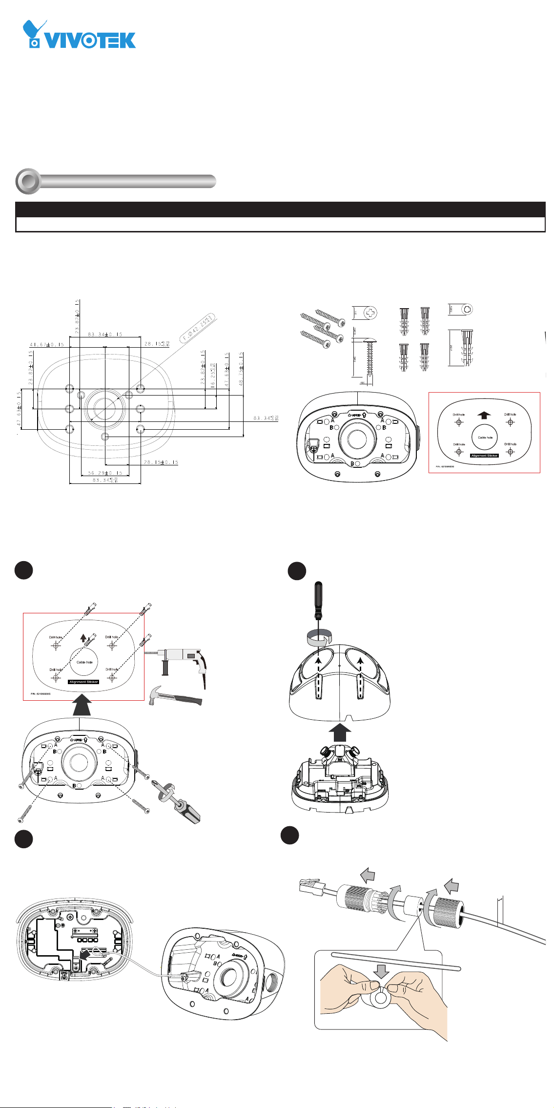
Mounting Dimensions
Installation
II
Compatible VIVOTEK Cameras
I
Compatible cameras/brackets
MS9390-HV
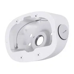
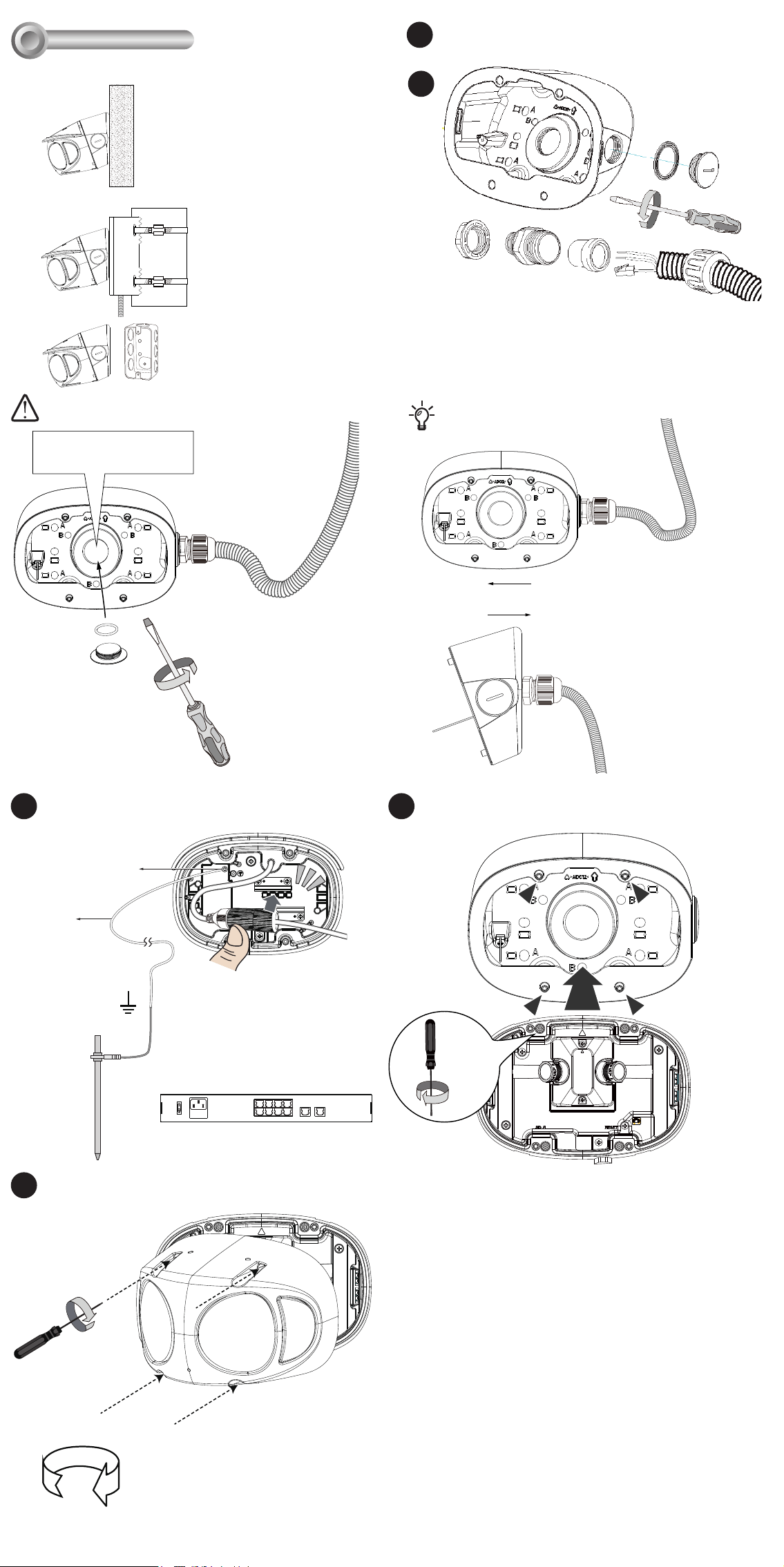
Remove the plastic plug on the conduit hole. A 3/4" conduit is
required for routing the cables with waterproof connection.
There are 3 mount types:
Install the cable gland and pass cables through it. The conduit
is user-supplied.
A
Accessory Ordering part no.: 100228700G
M4 X 25
unit: mm
Package Contents
Install the dome cover to the camera.
5.5 ~ 6.4mm
Attach the waterproof cable gland to the retention clips at the
back of the camera. Connect a grounding wire to the ground
screw of the camera.
Install the waterproof components of the cable gland to your
Ethernet cable following the QIG of your camera. The cable
gland will be placed within the protection of the tilt bracket.
If using the side hole,
seal the center hole.
OR
3/4”
Ø 6.5mm
Attach the included alignment sticker to a preferred position.
Drill holes on the wall and install the tilt bracket. If the space
behind the wall allows, you may also pass cables through the
wall.
A
C
B
A. Wall mount,
B. Pole mount via AM-312,
Corner mount via AM-412
C. to electrical junction box.
A-1
A-2
A-3
x4
Torque: 6.5±0.5kgf-cm
Remove the top cover from your camera.
Attach the tether wire to the back of the camera.
A-4
A-5
A-6
1.5m
Stainless SS M3*5
Green/Yellow
≥ 20AWG
A-7
x4
Torque: 6.5±0.5kgf-cm
Install the camera to the tilt bracket by fastening 4 T10
screws.
T10
A-8
1
2
3
4
6
5
8
7
10
LAN/PoE
100~240V
AC
ON
OFF
9
GE LAN GE LAN
802.3at
Open a live view console and adjust the shooting direction.
Refer to the camera's QIG for more information.
Install the cable conduit before wall-mounting. The conduit
can be installed from the side or through the center hole.
Revison History:
Rev. 1.0: Initial release
VIVOTEK Mounting Accessories
AM-21N Tilt Bracket
Installation Guide
Mounting Dimensions
Installation
II
Compatible VIVOTEK Cameras
I
Compatible cameras/brackets
MS9390-HV
Remove the plastic plug on the conduit hole. A 3/4" conduit is
required for routing the cables with waterproof connection.
There are 3 mount types:
Install the cable gland and pass cables through it. The conduit
is user-supplied.
A
Accessory Ordering part no.: 100228700G
M4 X 25
unit: mm
Package Contents
Install the dome cover to the camera.
5.5 ~ 6.4mm
Attach the waterproof cable gland to the retention clips at the
back of the camera. Connect a grounding wire to the ground
screw of the camera.
Install the waterproof components of the cable gland to your
Ethernet cable following the QIG of your camera. The cable
gland will be placed within the protection of the tilt bracket.
If using the side hole,
seal the center hole.
OR
3/4”
Ø 6.5mm
Attach the included alignment sticker to a preferred position.
Drill holes on the wall and install the tilt bracket. If the space
behind the wall allows, you may also pass cables through the
wall.
A
C
B
A. Wall mount,
B. Pole mount via AM-312,
Corner mount via AM-412
C. to electrical junction box.
A-1
A-2
A-3
x4
Torque: 6.5±0.5kgf-cm
Remove the top cover from your camera.
Attach the tether wire to the back of the camera.
A-4
A-5
A-6
1.5m
Stainless SS M3*5
Green/Yellow
≥ 20AWG
A-7
x4
Torque: 6.5±0.5kgf-cm
Install the camera to the tilt bracket by fastening 4 T10
screws.
T10
A-8
1
2
3
4
6
5
8
7
10
LAN/PoE
100~240V
AC
ON
OFF
9
GE LAN GE LAN
802.3at
Open a live view console and adjust the shooting direction.
Refer to the camera's QIG for more information.
Install the cable conduit before wall-mounting. The conduit
can be installed from the side or through the center hole.
Remove the top cover from the camera.
B
B-1
x4
Torque: 6.5±0.5kgf-cm
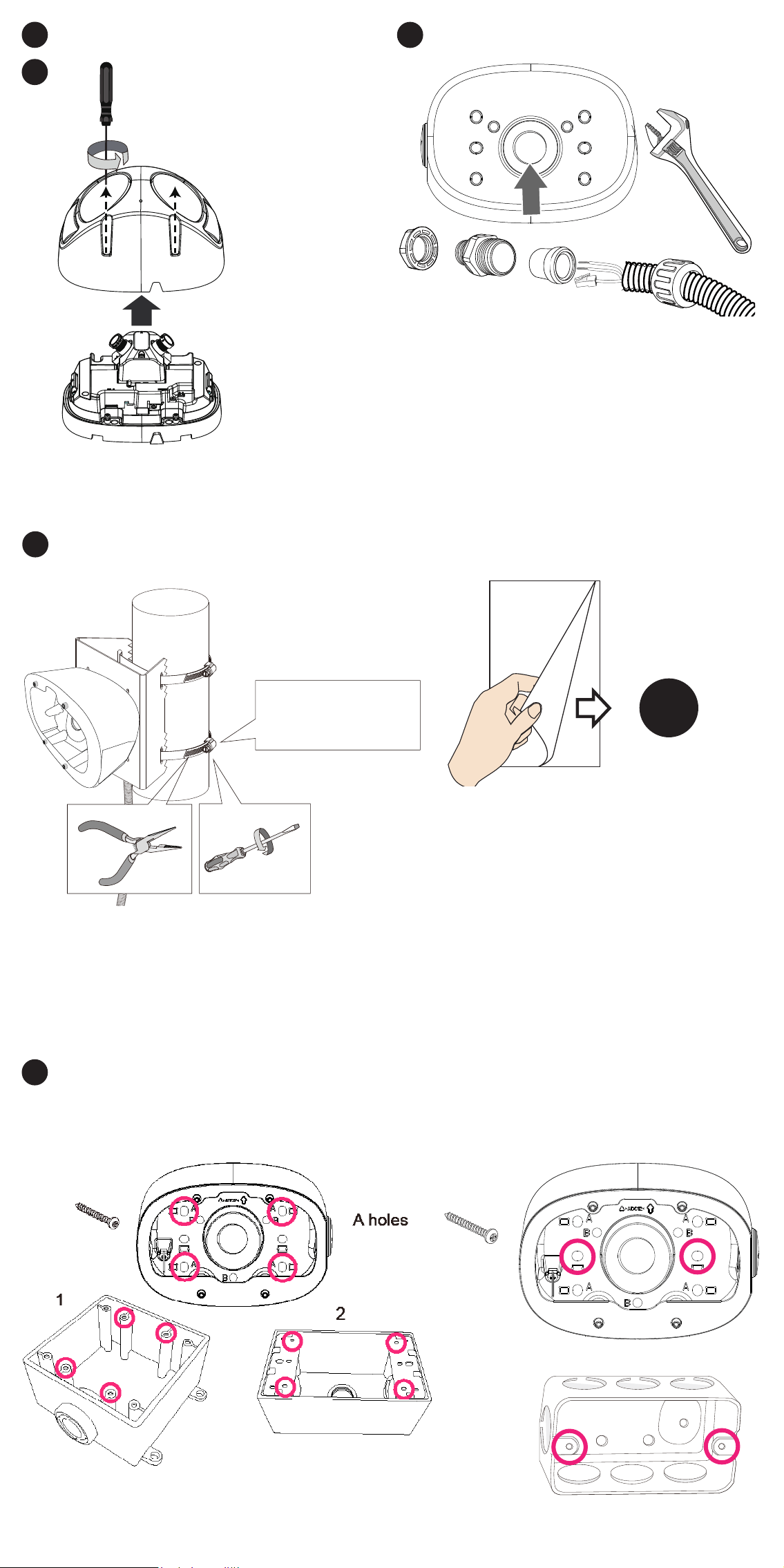
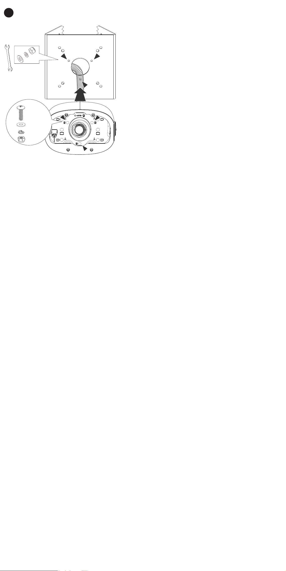
Install the tilt bracket to AM-312 using the included M4 screws,
washers and hex nuts. Pass the conduit through the center hole
of the AM-312.
B-2
AM-312
M4X15
B holes
B-3
Installation Torque:
35 lb-in(40kg-cm)
1. Pass the stainless steel straps through the bracket and around the
pole.
2. Tighten the straps using a pincer plier and a at blade screwdriver.
The tilt bracket supports the installation to the following electrical
boxes:
1. Cantex 3/4" type FSE 2 Gang, Outdoor/Indoor electrical box.
2. Generic 3/4" conduit box enclosure, 3/5 holes.
3. Single rectangular handy box.
C
A-4
Install a 3/4" conduit to the center hole. A 3/4" conduit is required
for routing the cables with waterproof connection.
B-4
Refer to Step A-4 for the rest of the installation process.
A holes
3
The rest of the installation steps are identical to those described
above.
Remove the top cover from the camera.
B
B-1
x4
Torque: 6.5±0.5kgf-cm
Install the tilt bracket to AM-312 using the included M4 screws,
washers and hex nuts. Pass the conduit through the center hole
of the AM-312.
B-2
AM-312
M4X15
B holes
B-3
Installation Torque:
35 lb-in(40kg-cm)
1. Pass the stainless steel straps through the bracket and around the
pole.
2. Tighten the straps using a pincer plier and a at blade screwdriver.
The tilt bracket supports the installation to the following electrical
boxes:
1. Cantex 3/4" type FSE 2 Gang, Outdoor/Indoor electrical box.
2. Generic 3/4" conduit box enclosure, 3/5 holes.
3. Single rectangular handy box.
C
A-4
Install a 3/4" conduit to the center hole. A 3/4" conduit is required
for routing the cables with waterproof connection.
B-4
Refer to Step A-4 for the rest of the installation process.
A holes
3
The rest of the installation steps are identical to those described
above.