Loading ...
Loading ...
Powered Liners Installation Detail:
MODEL MESH FILTERS MODEL BAFFLE FILTERS
C2000SD2 (SD2-NV) C2000BPB
C2000SD4 (SD4-12) C2000PSB
C2000BP (BP1-duct is offset to the left) C2000BP1-TW / TWB (requires 2 duct pipes)
C2000PS C2000PS1-TW / TWB (requires 2 duct pipes)
C2000PS-IS22 (Island Application)
C2000PS-IS28 (Island Application)
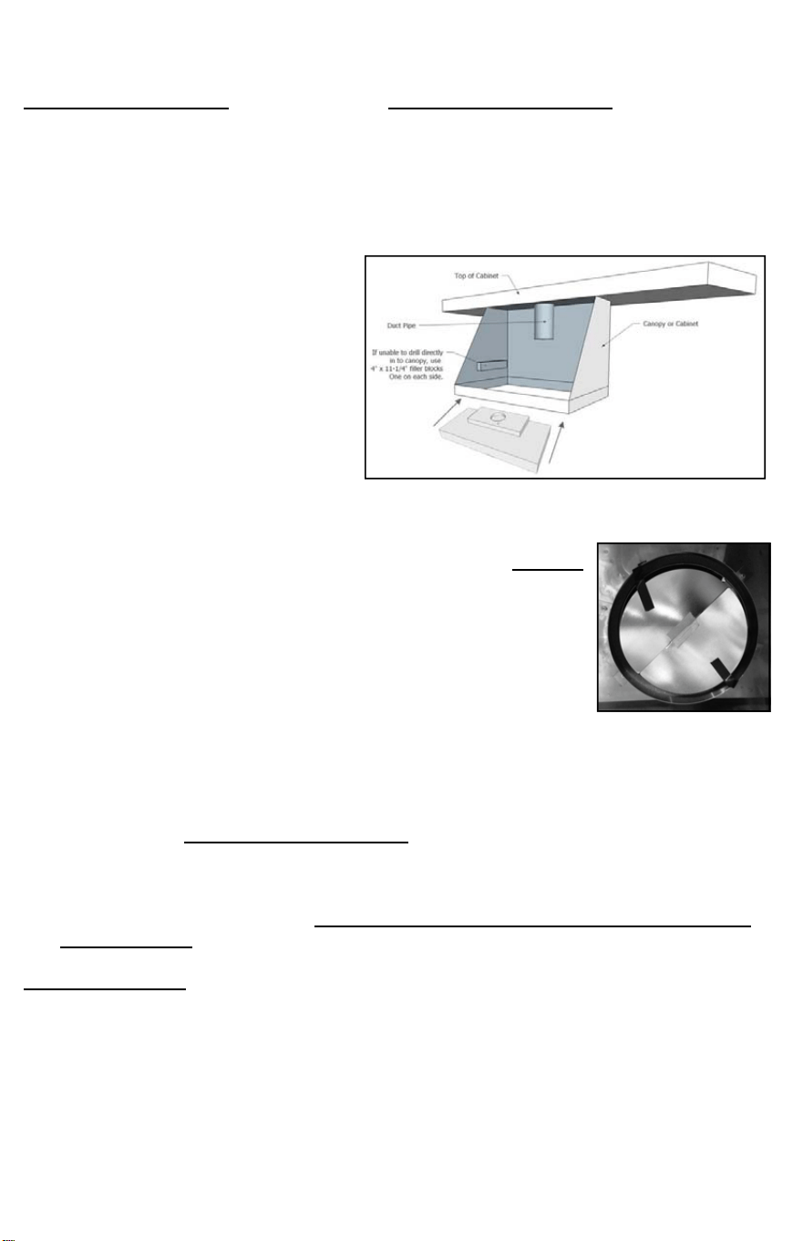
1. Line up powered liner to underside
of cabinet or canopy. If unable to
drill directly into cabinet or canopy,
use 4” x 11-1/4” x 3/4” wood blocks
(Figure 1) on the inside of canopy, left
and right side and secure with
screws.
2. Remove Filters of powered liner.
Remove the BLACK tape that holds
the damper blades closed.
(Figure 2) (It
is NOT recommended to use two (2)
dampers during installation. You have the option to use an external damper or use the
existing damper already on our unit.)
3. Raise and position powered liner so that the bottom is level with
cabinet and screw through holes on either side of liner. DO NOT
use Motor Mounts as Gripping Points. The duct pipe or pipes
should slip into the Automatic Seal Vent Collar. Additional Duct
Tape can be use if needed.
4. If required, additional mounting at the rear of the unit: Locate wall
studs, drill holes through back of insert to hit studs and attach the
liner to the wall with screws.
5. Island and Peninsula liners should be mounted in the same way
except there will be no rear wall mount.
6. Bring conduit down 4” past the bottom of the liner. NOTE: Top box
for the C2000BP1 shows vent opening Off-Set to the left (facing the hood). The lower
box will be the same size as the other models.
7. Remove junction box cover from C2000. (Be sure to comply with all local electrical and
safety codes.) Units are to be hard wired
. It is not recommended to add a power-
cord. Adding a power cord can loosen existing wires inside junction box causing
electrical failure.
8. Hook up electrical wires and secure inside junction box. Replace junction box cover.
Install lights and replace filters. For Baffle filters installation, see baffle installation
page enclosed.
TWIN UNITS ONLY—Transitioning two pipes into one is NOT recommended. CFMs are
reduced by 25% and will VOID the Performance Warranty.
DUCT SIZE INDICATOR - Our standard units have a 7” Round which can be transitioned to
8” Round or 10” Round to increase CFM.
See example below:
C2000PS-8 = 8” Round Transition
C2000PS-K = 10” Round Transition
(FIGURE 1)
(FIGURE 2)
Loading ...
Loading ...
Loading ...