Loading ...
Loading ...
Loading ...
7
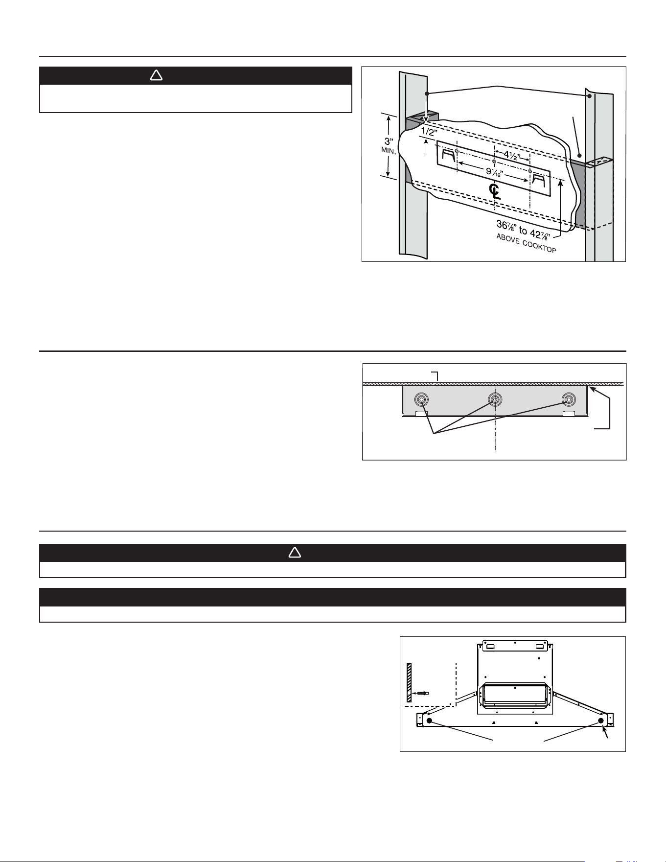
8. INSTALL HOOD MOUNTING BRACKET
Construct wood wall framing that is even with the surface of wall studs.
Wood wall framing must be at least 1/2” thick and 3” high. Fasten wood wall
framing to wall studs for a solid installation.
Make sure that the height of the framing will allow the mounting bracket
to be secured to the framing within the dimensions shown (see illustration
beside).
After wall surface is finished, carefully center and level the hood
mounting bracket over installation location. Secure it to wall framing using
3 no. 8 x 1½” screws.
Using a level, draw a vertical line up to the ceiling starting from the
mounting bracket center.
9. INSTALL UPPER FLUE MOUNTING BRACKET (DUCTED INSTALLATION ONLY)
10. INSTALL THE HOOD
WARNING
!
When cutting or drilling into wall, do not damage electrical
wiring and other hidden utilities.
Center the upper flue mounting bracket with the center line previously
drawn in step 8 and place it flush with the ceiling.
Use the upper flue mounting bracket as a template to mark the position of
its screws.
Drill the 3 screw holes using a 3/16” drill bit.
Insert the included drywall anchors into the drilled holes (1 per hole).
Secure the upper flue bracket to the wall using 3 no. 8 x 3/4” screws.
Ensure that the bracket is tight against the wall.
CAUTION
DO NOT REMOVE the protective plastic film covering the decorative flue (upper & lower) yet.
1. Align the hood and center it above the hood mounting bracket. Gently lower the
hood until it securely engages the bracket.
2. Level the hood.
3. With the hood hanging in place, mark both hole locations on wall (2 embossed
holes on back of hood; see illustration at right).
4. Remove the hood.
5. Drill through both marked holes on wall using a 3/16” drill bit. Insert the included
drywall anchors into the drilled holes (one for each hole).
6. Hang the hood to the wall bracket.
7. Secure the hood to the wall using 2 no. 8 x 3/4” screws and 2 washers.
36
7
/8” = BOTTOM OF HOOD 24” ABOVE COOKTOP
42
7
/8” = BOTTOM OF HOOD 30” ABOVE COOKTOP
SCREW LOCATIONS
HD0377
C
L
CEILING
MOUNTING BRACKET
FLUSH WITH CEILING
WARNING
!
BE CAREFUL when installing the decorative flue and hood, they may have sharp edges.
HOLE LOCATIONS
Ø 3/16” TYP.
HD0810A
SIDE VIEW
HD0813A
WALL STUDS
FRAMING BEHIND DRYWALL
NOTE: ILLUSTRATION ABOVE REPRESENTS HORIZONTAL
EXHAUST CONFIGURATION, BUT IT ALSO APPLIES TO
ALL CONFIGURATIONS.
Loading ...
Loading ...
Loading ...