FOR MODELS:
2VPTH09A-3.6
2VPTH12A-3.6
2VPTH15A-5.0
Before using your air conditioner please
read this manual carefully and keep it for
future reference, along with your receipt.
USER MANUAL
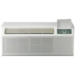
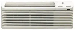
PACKAGED TERMINAL
AIR CONDITIONER
HEAT PUMP DC INVERTER
CONTENTS
UNIT FEATURES .............................................................2
INSTALLATION INSTRUCTIONS ....................................4
WIRING ............................................................................6
OPERATING INSTRUCTIONS.........................................7
ADVANCED OPERATION ................................................8
FUNCTION OF DIP SWITCHES......................................9
MAINTENANCE AND CLEANING .................................10
NORMAL OPERATING SOUNDS & CONDITIONS.......11
DIAGNOSTIC CODES & SOLUTIONS ..........................13
TROUBLESHOOTING ...................................................14
-1-
IMPORTANT NOTE TO THE SERVICER
Read this manual and familiarize yourself with the specific
items which must be adhered to before attempting to
service this unit. The precautions listed in this Installation
M
anual are intended as supplemental to existing
practices. However, if there is a direct conflict between
existing practices and the content of this manual, the
precautions listed here take precedence.
REC
OGNIZE THIS SYMBOL
AS A SAFETY PRECAUTION
THE MANUFACTURER WILL NOT BE RESPONSIBLE FOR ANY
INJURY OR PROPERTY, DAMAGE ARISING FROM IMPROPER
SERVICE OR SERVICE PROCEDURES. IF YOU INSTALL OR
PERFO R M SERV ICE ON T HIS UN I T, YO U AS SUME
RESPONSIBILITY FOR ANY PERSONAL INJURY OR PROPERTY
DAMAGE WHICH MAY RESULT, MANY JURISDICTIONS
REQUIRE A LICENSE TO INSTALL OR SERVICE HEATING AND
AIR CONDITIONING EQUIPMENT.
WARNING
IMPORTANT NOTES:
Before using this manual, check the serial plate for proper
model identification.
The installation
and servicing of this equipment must be
performed by qualified, experienced technicians only.
Due to policy of continual product improvement, the right is
reserved to change specifications and design without
notice.
IMPORTANT NOTE TO THE OWNER
This manual is to be used by qualified, professionally trained
HVAC technicians only. The manufacturer does not assume
any responsibility for property damage or personal injury for
improper service procedures or services performed by an
unqualified Person.
THE
FOLLOWING WARNINGS ARE
VERY IMPORTANT FOR SAFETY.
PLEASE READ THEM CAREFULLY
BEFORE INSTALLATION!
1. The air conditioner must be installed by
certified installer.
2. Check whether there is grounding wire
in the power supply system before
installation. If not, installers should refuse
installing and explain the safety principle to
users.
3. To avoid electric shock or even death,
the
socket or terminal blocks for power
supply to the air conditioner (include
277V and 115V and 208~230V series
and the units that have LCDI power
cord) must connect a Ground Fault Circuit
Interrupter.
4. During installation, the wire
connection must strictly follow the rule
zero line and fire line of unit should
be connected to the zero line and fire line
in the power system. The connection
in reverse is forbidden. Please be sure
the ground wire is firmly connected
otherwise it is possible to result in the
electrical shock or death.
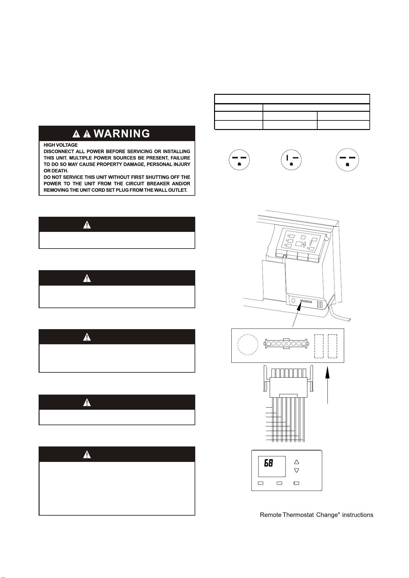
WARNING
HIGH VOLTAGE
DIS CONNEC T ALL P OWER BEFOR E SERVICING OR
INSTALLING THIS UNIT. MULTIPLE POWER SOURCES MAY
BE PRESENT, FAILURE TO DO SO MAY CAUSE PROPERTY
DAMAGE, PERSONAL INJURY OR DEATH.
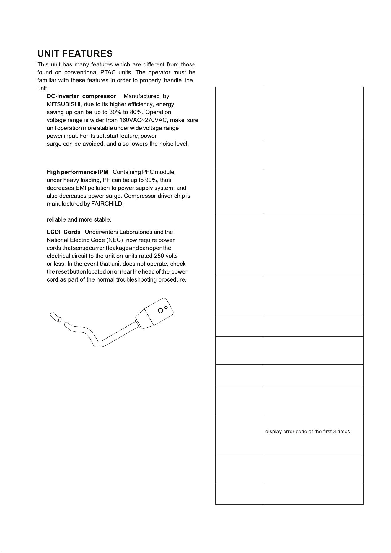
LCDI power Cord
Automatic 3-minute compressor lockout: After
the compressor cycles off, it will not restart for three
minutes.
Random restart delay: To help eliminate power
surges after a power outage, the unit is equipped with
two to four minute random restart delay feature.
Whenever the unit is plugged in with the master
switch turned on and the mode switch set in the cool
or heat mode, a random restart will occur. A random
restart condition can be avoided by setting the mode
switch in the fan only or off position before applying
power to the unit.
Indication LEDs : The control panel has LEDs that
correspond to fan operation and to indicate unit status.
The LEDs next to the selections ON/OFF, FAN, COOL,
and HEAT indicate which mode is active.
- 2 -
Without frequently starting-stopping, the room
temperature is more stable & more comfortable.
a known brand providing
high performance, making the compressor more
:
:
System safety protection
To ensure the system is running safely, the electric
control has the following protections. For problem
solving, please refer to Diagnostic Codes & Solutions
and Troubleshooting sections, pages 13 & 14.
When condenser coil temperature ex-
ceeds the presetting point, compressor
decreases the operating frequency to
30Hz. If this protection is inactive and
condenser coil temperature reaches the
shut-down point, the compressor will
be turned off. Thus providing double
protection.
Outdoor unit
overload
protection in
COOLING mode
Evaporator freeze
protection (will
not display error
code)
When evaporator coil temperature drops
to 1°C and lasts for 5 minutes, compres-
sor and outdoor fan will stop, indoor fan
keeps on running.
When compressor discharge tempera-
ture reaches protection point, compres-
sor will decrease operating frequency
to 30Hz. If this protection is inactive and
discharge temperature reaches the shut
down point, compressor will be turned
off. Thus provide double protections.
Compressor
discharge
overheating
protection
When evaporator coil temperature
exceeds the presetting point, compres-
sor decreases the operating frequency
to 30Hz. If this protection is inactive and
evaporator coil temperature reaches
the shut down point, compressor will
be turned off. Thus provide double pro-
tections. This time the back up electric
heater will be turned on.
Evaporator
overload
protection
(heat pump
mode)
When input current exceeds the pre-
setting point, compressor will decrease
the operating frequency to 30Hz. If this
protection is inactive and current reach-
es the shut down point, compressor will
be turned off.
Input over
current
protection
Compressor over
current protection
When compressor operating current ex-
ceeds the shut down point, compressor
will be shut down.
When IPM faults, include over heat,
unit will be shut down, all outputs are
terminated, control panel displays the
error code.
IPM fault
protection
Temperature
sensor fault
Any temperature sensor faults, unit
stops and display the error code.
protection
For continuously 2 minutes communi-
cation faults between indoor unit and
outdoor unit, unit will shut down and
displays error code.
Communication
fault protection
If compressor starting fails, 3 minutes
later, it will try to start again. It will not
fault. If the 4th time fail again, it will not
start any more and display the error
code.
Compressor
starting fault
DC-DC-BUS o
voltage/under
voltage
protection
Once monitors the DC-BUS is over or
under voltage, unit stops and display
error code.
When the unit is powered on, if system
monitors the EEPROM fault, displays er-
ror code and will not operate any more.
EEPROM fault
:
Wall Sleeve Kit
Key Lock Kit
Drain Kit
Filter Kit
Wire Harness Kit
Architectural Grille Kit
Stamped Louver
Kit
LCDI Power Cord
Wireless IR Thermostat
Electric And Non Electric Sub Base Kit
IR REMOTE CONTROLLER
NOTE: Consult sales literature for the appropriate
voltage and amperage selections, if applicable.
- 3 -
R LS GH B Y W GL C
WALL MOUNTED THERMOSTAT INTERFACE
The control logic as
belw:
1.Turn ON unit:short circuit R and LS then release for
one time within 5 seconds.
2.Turn OFF unit:short circuit R and LS then release for
twice within 5 seconds.
3.Force unit shut down for one time:connect LS to R for
over 5 seconds.
NOTE: After force shut down, you can turn the unit ON
again by hand-held remote controller or the control panel.
:
:
:
:
:
:
:
:
:
(SOLD SEPARATELY)
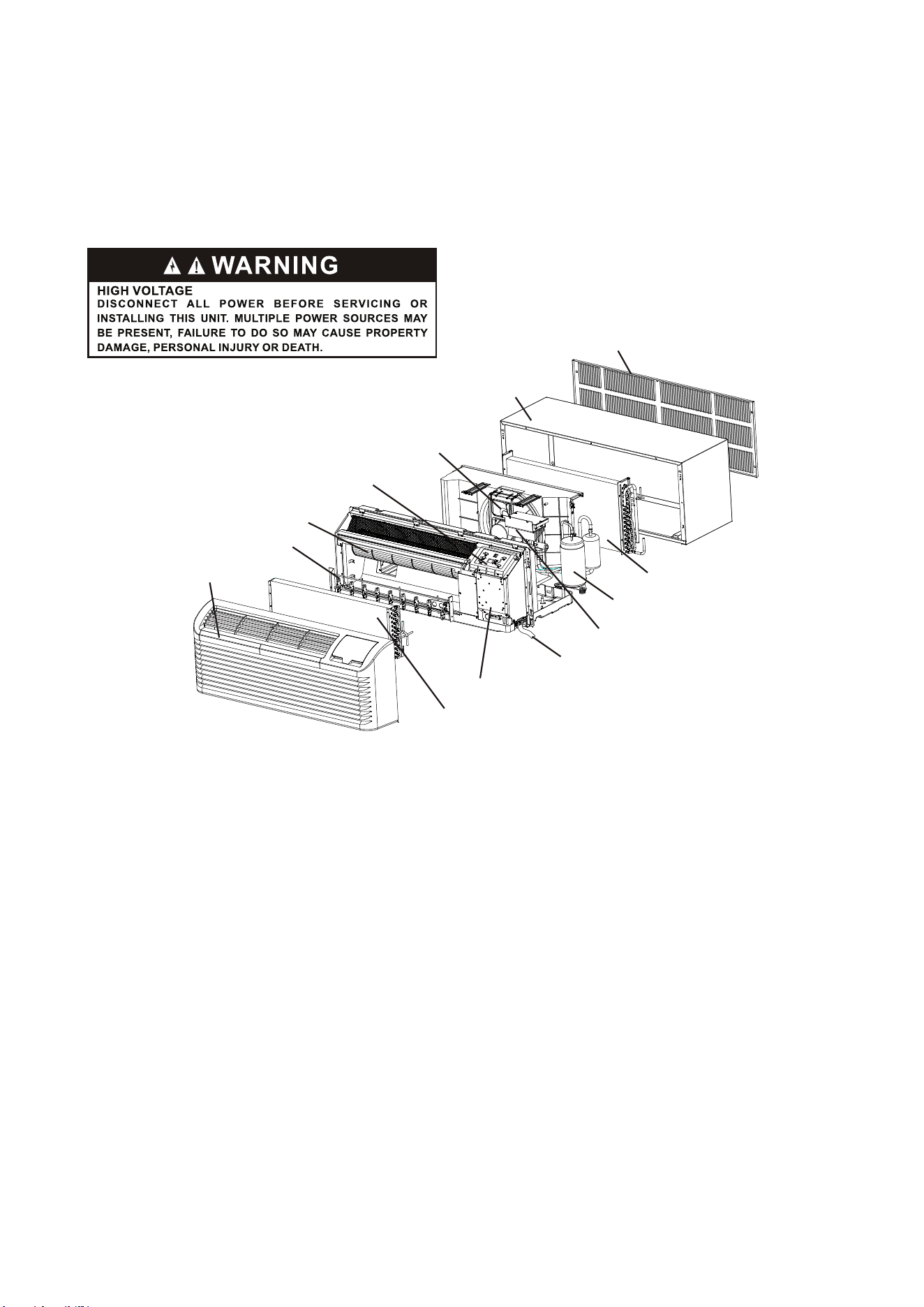
Wall sleeve
Outdoor coil
Outdoor grille
Front and discharge grille
Electric heater
Indoor Fan
Display Module
Outdoor Fan
Inverter compressor
Power cord coverplate(not show)
Electronic control module assembly
Control box
Indoor coil
- 4 -
INSTALLATION INSTRUCTIONS
To ensure that the unit operates safely and efficiently, it must be installed, operated and maintained according
to these installation and operating instructions and all local codes and ordinances or, in their absence, with the
latest edition of the National Electric Code. The proper installation of this unit is described in the following
sections. Following the steps in the order presented should ensure proper installation.
-5-
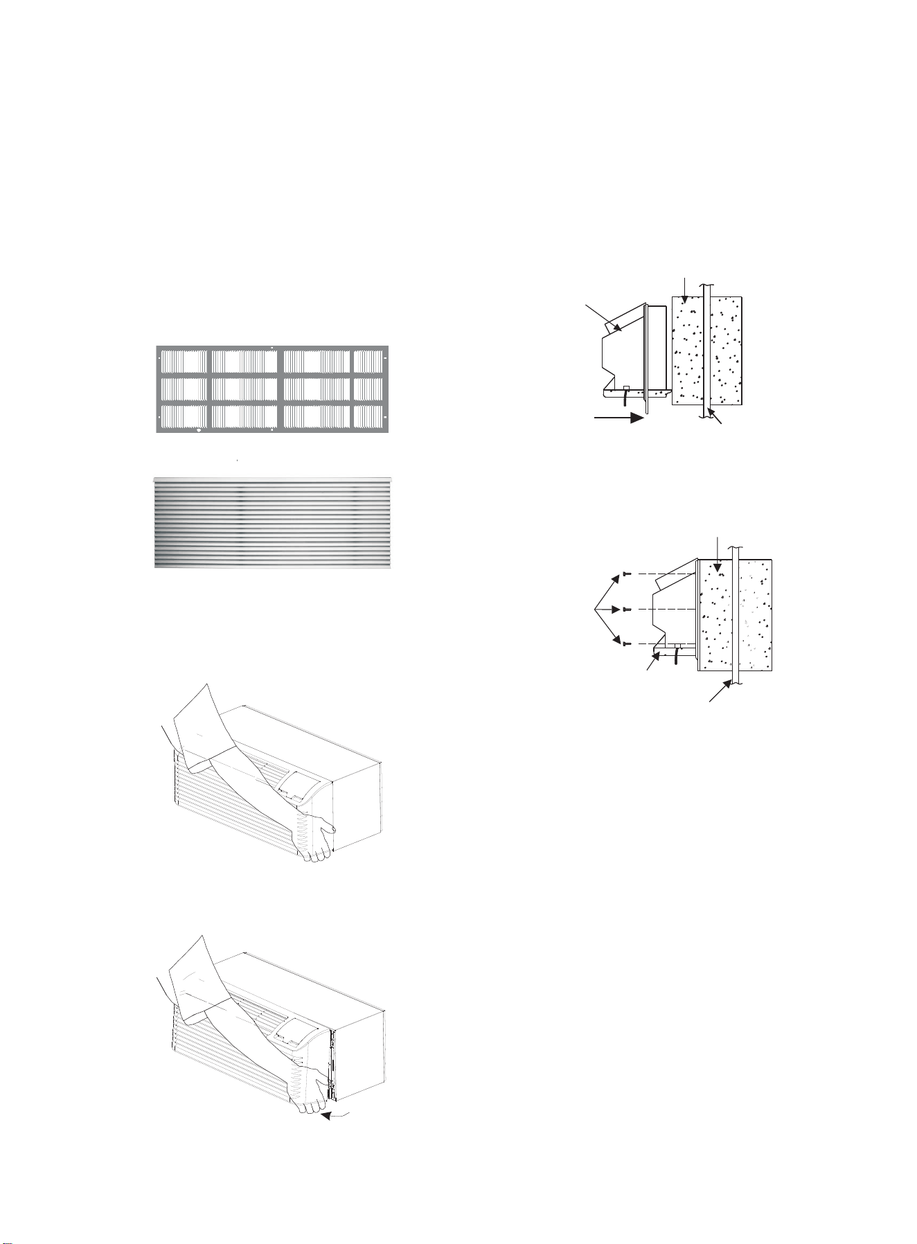
OUTDOOR GRILLE
(SOLD SEPERATELY)
An outside grille must be installed to direct air flow for
proper unit operation and also protect the outdoor coil. The
grille must be installed before installing the chassis.
When replacing an old chassis with an existing grille or
using a specialized grille in a new installation, please
check with
supplier to determine if the new chassis
should be used with the nonstandard specialized grille.
An improper outdoor grille can decrease cooling or
heating capacity, increase energy usage and shorten
compressor life and possibly void the warranty.
2. Insert the chassis into the wall sleeve.
Wall Sleeve
Chassis
Flush Stamped Louver
Slide Chassis in Outside wall
Chassis Installation View 1
Architectural Louver
Wall Sleeve
Screws
CHASSIS INSTALLATION
1. Remove the cabinet front from the chassis as described
below (1a and 1b).
(3 on each
side of unit)
• Grasp the cabinet front.
Chassis
Outside wall
Chassis Installation View 2
3. Secure the chassis to the wall sleeve using three screws
on each side of the chassis to ensure a proper seal
between the chassis and the wall sleeve. The screws are
supplied in a plastic bag.
IMPORTANT NOTES:
Cabinet Front Removal View 1
• Pull the bottom of the cabinet front away from the
chassis until the retaining clips disengage.
Cabinet Front Removal View 2
• Remove shipping tape from front panel as shown in
Figure 12 on page 8
• Remove shipping screw from vent door as shown in
Figure 13 on page 8.
1. The unit is equipped with a rubber grommet mounted
compressor. These grommets are factory set and require
no adjustment.
2. Check the indoor and outdoor grilles for obstructions to
air flow. The unit must be located where curtains, furniture,
trees, or other objects do not block the air flow to and from
the unit. If air is obstructed and/or deflected back into the
unit, the air conditioner compressor may cycle on and off
rapidly. This could damage the compressor or possibly
void the warranty.
• Slide the chassis into the wall sleeve until the chassis
flanges contact the front edge of the wall sleeve.
VOLTAGE MEASUREMENTS
Once the unit is properly wired, measure the unit supply
voltage. Voltage must fall within the voltage utilization
range given in .Chart 3
WIRING
230~208V units are equipped with LCDI power cords and
can open the electrical circuit to the unit. In the event the
unit does not operate, check the reset button located on or
near the head of the power cord as part of the normal
troubleshooting procedure.
WARNING
THIS AIR CONDITIONER IS NOT MEANT TO PROVIDE
UNATTENDED COOLING OR LIFE SUPPORT FOR PERSONS
OR ANIMALS WHO ARE UNABLE REACT TO THE FAILURE OF
THIS PRODUCT.
THE FAILURE OF AN UNATTENDED AIR CONDITIONER MAY
RESULT IN EXTREME HEAT IN THE CONDITIONED SPACE
CAUSING OVERHEATING OR DEATH OF PERSONS OR
ANIMALS.
Operating Voltage
Rating
230/208
Unit Voltage
Minimum
197
Voltage Utilization Range
Maximum
253
Chart 3 -Operating Voltage
-6-
RED-24VAC
Purple-LS control
Green-High fan speed
Blue-Reversing valve
Yellow-Compressor
White-Heater
Orange-Low fan speed
Black-Common ground
R LS GH B Y W GL C
R LS GH B Y W GL C
WALL MOUNTED THERMOSTAT INTERFACE
Thermostat
WARNING
TO AVOID THE RISK OF PROPERTY DAMAGE, PERSONAL
INJURY OR , USE ONLY COPPER CONDUCTORS.FIRE
WARNING
TO AVOID PROPERTY DAMAGE, PERSONAL INJURY OR
DEATH DUE TO ELECTRICAL SHOCK, DO NOT USE AN
EXTENSION CORD WITH THIS UNIT.
WARNING
TO AVOID THE RISK OF PROPERTY DAMAGE, PERSONAL
INJURY OR FIRE DO NOT INSTALL WITH POWER CORD
STRETCHED OR UNDER A STRAIN AS THIS MAY CREATE
LOOSE PLUG/RECEPTACLE CONNECTION.
WARNING
TO AVOID THE RISK OF PERSONAL INJURY, WIRING TO THE
UNIT MUST BE PROPERLY POLARIZED AND GROUNDED.
Fig 9 wall mounted thermostat wiring
Fig 8 Receptacles/Sub-bases
before
NOTE: See the “
us
ing the thermostat.
Tandem
230/208V 15Amp
Perpendicular
230/208V 20 Amp
Large tandem
230/208V 30Amp
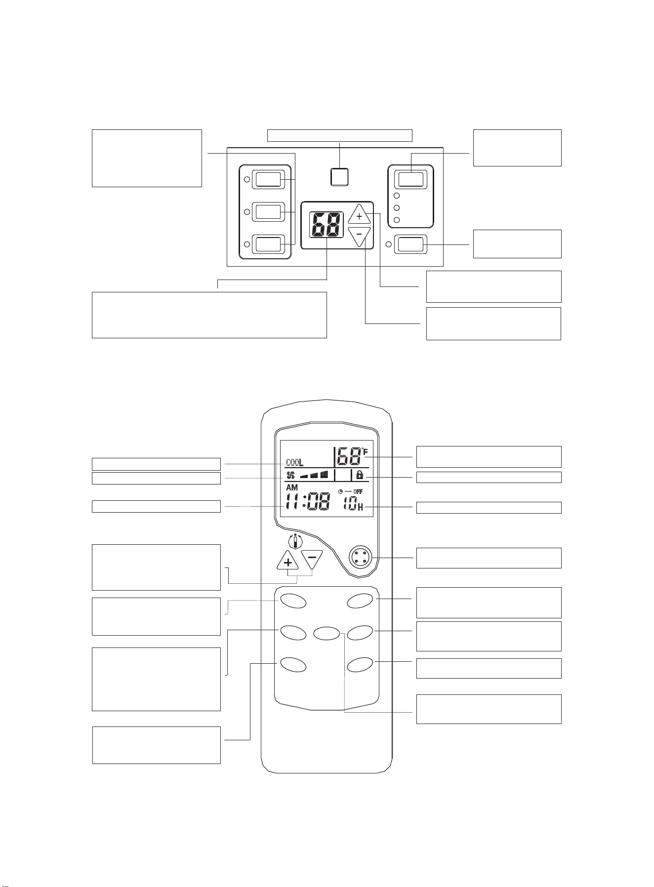
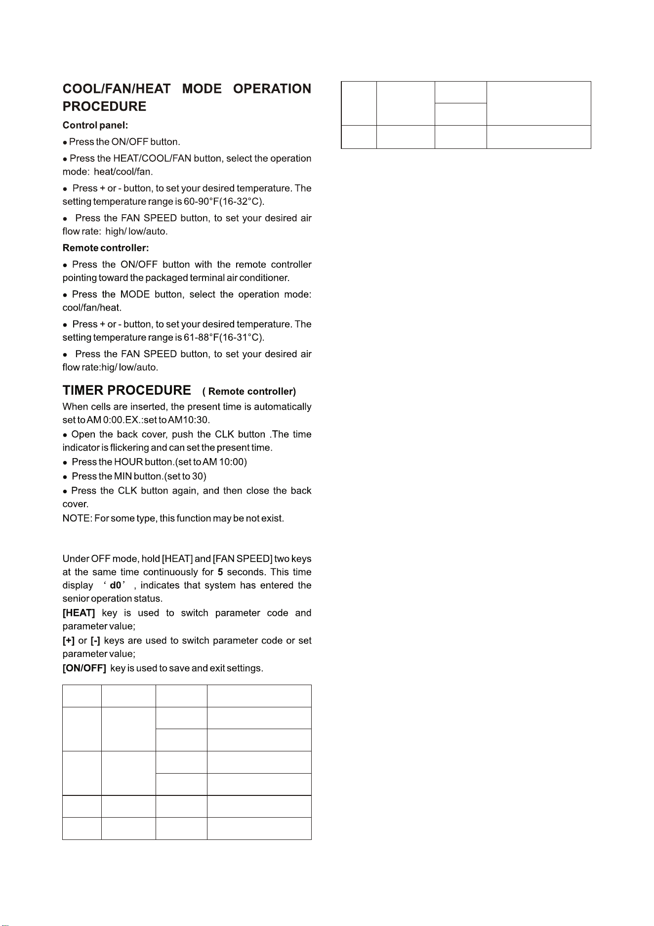
OPERATING INSTRUCTIONS
Operation mode button s
Press these buttons to
select the unit operating mode:
Heat, Cool, or Fan. The
indicator on the left will display
your selection.
HEAT
COOL
FAN
ON/OFF
AUTO
LOW
HIGH
SPEED
FAN
Digital displayer
In normal operation, indicates room temperature;
When pressing + or - button, it indicates setting temperature;
On time operation, it indicates timer time;
On failure operation, it indicates failure code.
Fan Speed button
Press this button to select
the fan speed on high, low or
auto.
Receiver of IR remote controller signal
ON/OFF button
Press this button to turn the
unit ON or OFF.
+ button
Press this button to increase the room
temperature setting.
– button
Press this button to decrease the
room temperature setting.
Fig 10 Use of unit mounted control panel
-7-
Fig 11 Use of hand held remote controller (optional)
Fan speed indicator
Present time indicator
TEMP setting button
This button is used to sent the room
temperature. Pressing of + or - button,
the temperature setting is increased or
decreased.
FAN SPEED button
Press this button to select
high/low/auto speed of fan speed.
TIMER button
This button is used to set the time-
on or time-off mode. Used together
with the HOUR button, the time
setting can be made within the range
of 1-12 hours, with an interval of one
hour.
HOUR button
This button is used to set the present
time or to set the timer to switch-on or
switch-off.
TEMP indicator
Indicates set temperature
Keyboard locked indicator
Timer time indicator
ON/OFF button
Press this button to turn the unit on or off.
Operation Mode button
This button is used to select the Cool,
Fan or Heat mode of operation.
HOLD button
Press this button to lock/ unlock the
keyboard.
MIN button
This button is used to set the present time.
Operation mode indicator
°C/°F button
This button is used to switch Fahrenheit
and Celsius temperature.
F
A
N
S
P
E
E
D
T
I
M
E
R
H
O
U
R
E
D
O
M
D
L
O
H
N
I
M
ON/OFF
°C °F/
-8-
Parameter
code
Function
Parameter
value
Explanation
d0
Unit of
temperature
F
C
Fahrenheit(default)
Celsius
d1
Operation way
selection
By control panel or IR remote
thermostat (default)
By 24V universal remote
thermostat
r
P
d2
Top temperat-
ure setting
d3 to 32℃/90℉
The minimum value is d2
(default 32℃/90℉)
d3
Bottom temp-
erature setting
16℃/60℉ to d2
The maximum value is d3
(default 16℃/90℉)
d4
-9℃ to 9℃
Indoor tempera-
ture calibration
-9℉ to 9℉
If unit of temperature is changed,
calibration should be done again.
If use the default value, it can be
ignored. (default 0℃/0℉)
1 indicates displaying room temp-
erature, 0 for setting point
(default 0)
d5
Temperature dis-
play selection
0 or 1
One setting example:
Setting target: d0(C), d1(r), d2(30℃),d3(18℃),d4(-
1℃),d5(1).
Step1: hold [HEAT] and [FAN SPEED] two keys at the
same time continuously for 5 seconds.
Display:'d0'
Step2: short press [HEAT] key.
Display:'F'
Step3: short press [+] or [-] key.
Display:'C' (setting d0 has finished)
Step4: short press [HEAT] key.
Display:'d0'
Step5: short press[+] key.
Display:'d1'
Step6: short press [HEAT] key.
Display:'P'
Step7: short press[+] or [-] key.
Display:'r' (setting d1 has finished)
Step8: short press [HEAT] key.
Display:'d1'
Step9: short press[+] key.
Display:'d2'
Step10: short press [HEAT] key.
Display:'32'
Step11: short press [-] key twice.
Display:'30' (setting d2 has finished)
Step12: short press [HEAT] key.
Display:'d2'
Step13: short press[+] key.
Display:'d3'
Step14: short press [HEAT] key.
Display:'16'
Step15: short press [+] key twice.
Display:'18' (setting d3 has finished)
Setp16: short press [HEAT] key.
Display:'d3'
Step17: short press[+] key.
Display:'d4'
Setp18: short press [HEAT] key.
Display:'0'
ADVANCED OPERATION
Step19: short press [-] key.
Display:'-1' (setting d4 has finished)
Setp20: short press [HEAT] key.
Display:'d4'
Step21: short press[+] key.
Display:'d5'
Step22: short press [HEAT] key.
Display:'0'
Step23: short press [+] or [-] key.
Display:'1' (setting d5 has finished)
Step24: short press [ON/OFF] key to save and exit
settings.
-9-
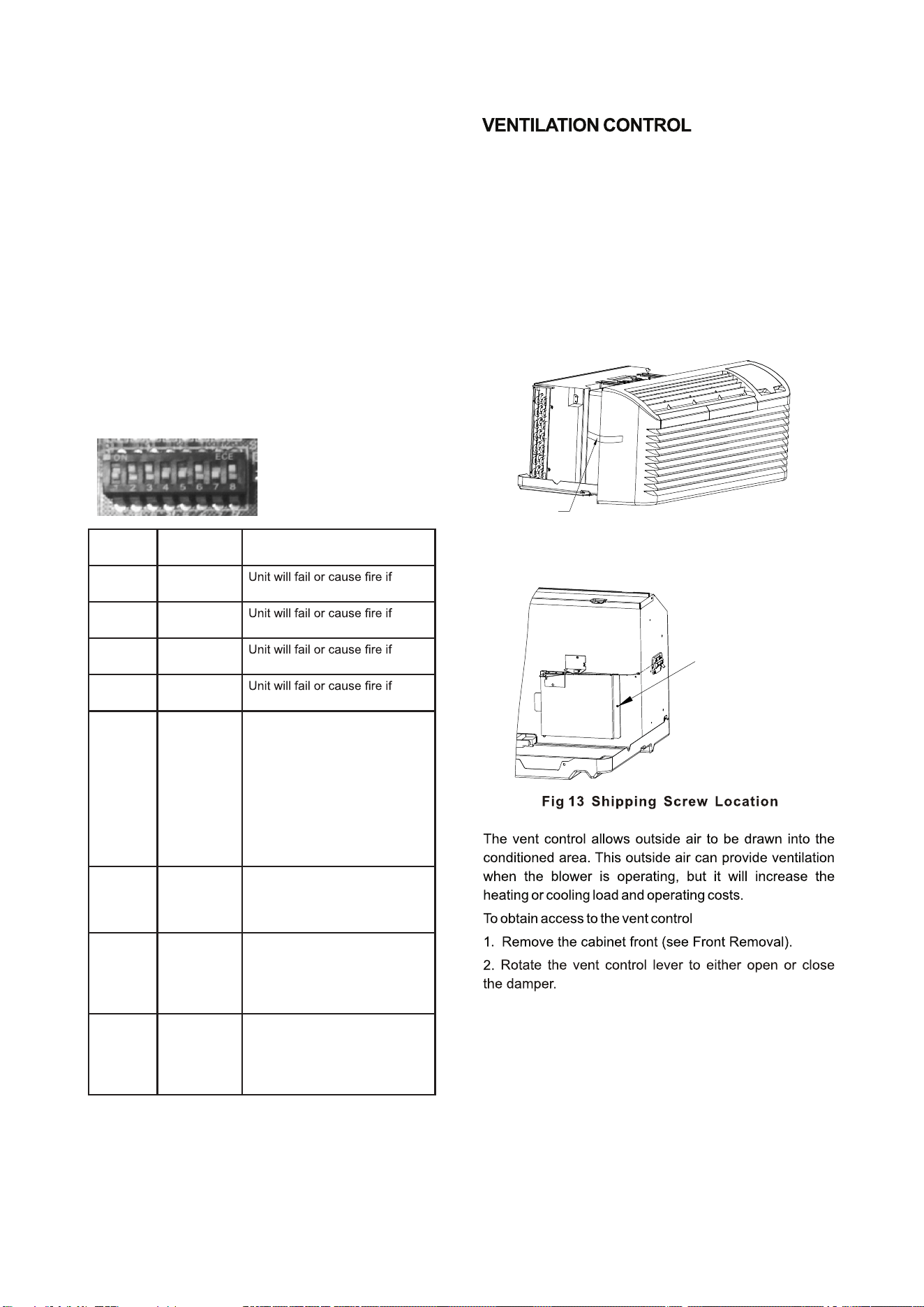
FUNCTION OF DIP SWITCHES
(putting to ON position makes the function active)
Remove shipping
screw if present
Shipping
tape
Fig 12 Shipping tape Location
DIP
Switches
Function Description
1 Reserved
changed. Keep default setting.
2 Heat Pump
changed. Keep default setting.
3 Electric Heat
changed. Keep default setting.
4 Reserved
changed. Keep default setting.
ON - When the unit is connected
to the power supply, and the
room temperature is lower than
10°C/50°F for 3 min., the unit
will start heating automatically
no matter the mode. Only when
the room temperature reaches
13°C/55°F will heating stop. If in
the OFF position there will be no
freeze protection.
5
Freeze
Protection
ON - If the unit losses power,
once the power is restored
the unit will run the previous
settings.
6
Electric
Memory
Fan for
Heating
ON - Enables the fan to run con-
tinuously when heating. Default
setting is cycling fan in heating
mode.
7 Continuosuly
(CON)/Cycle
(CYC)
Fan for
Cooling ON - Enables the fan to cycle
when cooling. Default setting is
continuous fan in cooling mode.
8 Cycle (CYC)/
Continuosuly
(CON)
The ventilation control lever is located at left side of unit
behind front panel.
NOTE: The vent door shipping tape must be removed
before using vent control lever. See Fig. 12 and Fig. 13.
When set at Close, only the air inside the room is
circulated and filtered;
When set at Open, some outdoor air will be drawn into
the room; this will reduce heating or cooling efficiency.
-10-
Location of 7 Screws
Vent door lever positions
MAINTENANCE AND CLEANING
WARNING
HIGH VOLTAGE
DIS CONN ECT ALL POW ER BEFO RE SERVICI NG OR
INSTALLING THIS UNIT. MULTIPLE POWER SOURCES BE
PRESENT, FAILURE TO DO SO MAY CAUSE PROPERTY
DAMAGE, PERSONAL INJURY OR DEATH.
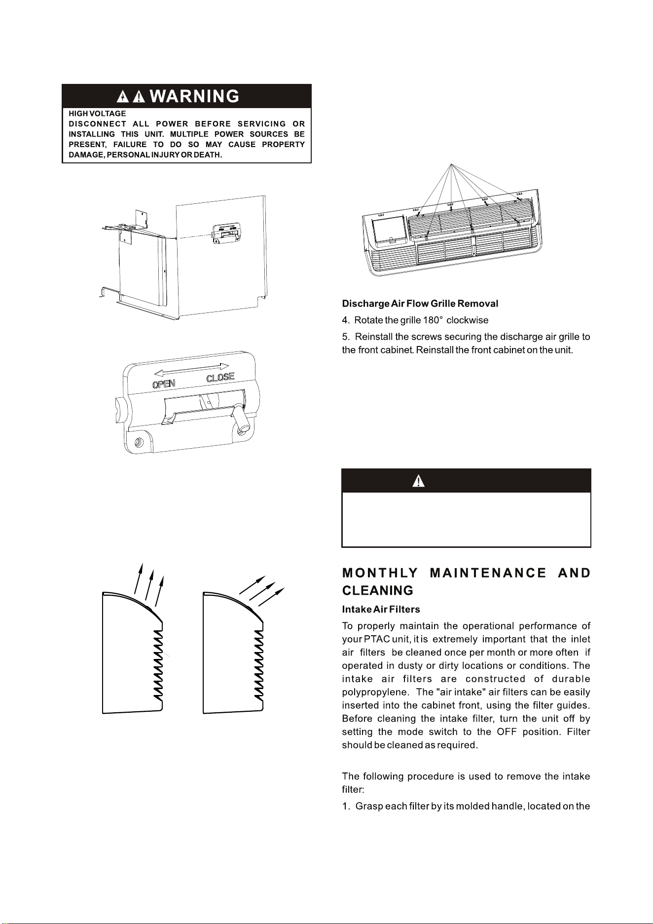
Discharge Air Flow
3. Remove the seven (7) screws which secure the
discharge air grille to the cabinet front.
AIR DISCHARGE GRILLE
The discharge grille can be adjusted to expel air at
either a 15°or 55°angle。
Discharge Grille Orientation Options
15°
Discharge
Air
55°
Discharge
Air
Use the following procedure to change the angle of the
discharge air flow:
1. Remove the front cabinet (see Front Removal).
2. Position the front so that the backside is accessible.
Front
Back
(pg. 5)
front edge of the front panel, below the discharge grille.
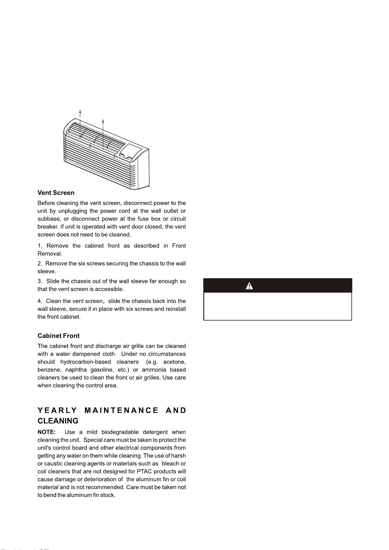
Base pan and Condenser coil
Before cleaning the base pan and condenser coil, turn
OFF unit mode switch and disconnect power to the unit.
To disconnect power, either unplug the power cord at the
wall outlet or subbase, or disconnect power at the fuse box
or circuit breaker
1. Create a water tight seal by tightly covering the entire
control panel area and fan motor with plastic. Creating this
seal prevents water from entering the control area or the
fan motor and damaging the unit.
2. Spray condenser coil and base pan down with water.
Next spray a mild biodegradable detergent onto the
condenser coil and base pan. Let set for five (5) minutes.
3. Rinse condenser coil and base pan with water again.
NOTE: Ensure water pressure is no higher than that of an
ordinary garden hose and the water temperature no higher
than 120℉.
-11-
Routine scheduled Maintenance
To achieve continuing top performance and high efficiency,
establish a “once a year" cleaning/inspection schedule for
the unit. Take the unit out of the sleeve and thoroughly
clean and rinse. Be sure to include in the yearly cleaning
the evaporator coil, and condenser coil, basepan, and
drain passages.
Scheduled maintenance can be accomplished by either
qualified local maintenance staff or by an authorized
servicer. They must follow the instructions described in this
manual.
Adverse Operating Conditions Maintenance
Units operating in dusty or corrosive locations; i.e.
dusty construction site or sea coast, must be cleaned
more often. A minimum of four (4) times a year will
maintain proper operational conditions and protect unit
components.
Wall sleeve
Clean the wall sleeve while cleaning the unit. The
caulking around the sleeve should be checked to make
sure that any potential air and water openings around
the sleeve are properly sealed. The wall sleeve's level
should also be rechecked. Proper leveling for most
installations are a 1/4 bubble tilt to the outside and
level from right to left. Contact your sales person for
detailed maintenance or cleaning instructions.
The front panel does not
need to be removed.
Filter is removed by grasping
the filter's top and gently
pulling up
2. Pull the filter straight up and remove.
3. Clean filter with vacuum or with running water.
Reverse this procedure to reinstall the filter.
CAUTION!
DO NOT USE COMMERCIAL GRADE COIL CLEANERS. SOME
OF THESE CLEANERS MAY CONTAIN ETHYLENE DIAMINE
TETRACETIC ACID (EDTA) WHICH CAN SHORTEN THE LIFE
OF THE CONDENSER COIL.
4. Tilt the non-compressor side of the unit up no higher
than 45 degrees and allow water to drain out the other side
of the unit.
5. Remove excess water left in the base pan by wiping the
base pan with a dry cloth.
6. Remove the water-tight seal from the motor and
control panel area.
7. Reinstall unit back into wall sleeve.
8. Allow unit to dry for 24 hours before reapplying power.
When power is reapplied test unit for proper operation.
9. Place a non-acidic algaecide in the base pan to inhibit
bacteria growth. Ensure the algaecide is compatible with
wet coil operation and is not corrosive to the coil.
Clearance Check
Clearances around the unit should also be checked to
make sure that the intake air and discharge air paths have
not become blocked or restricted. A minimum of eight
inches clearance is needed from unit to furniture, beds, or
other objects for proper operation. Restricted discharge or
intake air will reduce the unit's operational performance. In
severe airflow restrictions damage can occur to unit
components such as the compressor, electric heater or fan
motor.
NORMAL OPERATING SOUNDS
AND CONDITIONS
Water trickling sounds
Water is picked up and distributed over the coil. This
improves the efficiency and helps with water removal.
Water dripping
Water will collect in the base pan during high humidity
days. This can cause overflow and drip from the outside of
the unit.
Air sounds
The fan cycle switch sets the operational mode of the fan.
In the ON position the fan will run continuously whenever
power is applied in this mode. In the AUTO position, the
fan will cycle on and off with the compressor or electric
heater.
Starting delay
You may notice a few minutes delay in the starting if you
try to restart the unit too soon after turning it off or if you
adjust the thermostat right after the compressor has
shut off. This is due to a built–in delay to protect the
compressor.
Buzzer Response
The buzzer will chime “Di”(0.1 sec) as response when
receiving the effective order from key pad control and
remote control.
-
12-
CAUTION!
HIGH PRESSURE AND HIGH TEMPERATURE CLEANING IS
NOT RECOMMENDED.
DOING SO COULD DAMAGE THE ALUMINUM FIN STOCK
AND ELECTRICAL COMPONENT.
DIAGNOSTIC CODES & SOLUTIONS
The Diagnostic Maintenance provides detailed information on PTAC control operation and operational status including
present modes, failures , airflow restriction warnings , operating temperatures, and past failures.
Failure code
Content of defect
F1
Communication failure between
indoor unit and outdoor unit
Solutions
Check the communication cables, make sure they are
firmly connected. If the cables are broken, replace them.
F2
Indoor ambient temperature
sensor fault
Check the plug is firmly connected. If the sensor is
broken, replace it.
F3
Indoor coil temperature sensor
fault
Check the plug is firmly connected. If the sensor is
broken, replace it.
F5
IPM protection, include heat sink
over heat protection
Make sure indoor and outdoor units vents are not
blocked, indoor fan and outdoor fan are running well
and compressor will not overload. After removing any
fault, power the unit on again for rest.
F6
Outdoor ambient temperature
sensor fault
Check the plug is firmly connected. If the sensor is
broken, replace it.
F7
Outdoor coil temperature
sensor fault
Check the plug is firmly connected. If the sensor is
broken, replace it.
F9
Compressor discharge
temperature fault
Check the plug is firmly connected. If the sensor is
broken, replace it.
FC
DC compressor starting failure or
compressor driving fault
Check the DIP switches on the main board (3-position,in
red color) is correct, it must matches the wiring diagram.
Make sure the compressor power wires is firmly connected.
FH
Indoor EEPROM fault, include
EEPROM communication fault or
data verification error
Check the EEPROM chip is firmly plugged. If still not
solve, replace the chip.
P1
Over heat at indoor coil protection
in HEATING (overload in heating).
Over heat at outdoor coil protection
in COOLING (overload at cooling).
Make sure indoor and outdoor unit vents are not blocked
and indoor fan and outdoor fan are both working well.
Clear the air filter and the condenser after a long time use.
P2
DC inverter module overheat,over
current protection
Make sure indoor and outdoor unit vents are not blocked
and indoor fan and outdoor fan are both working well.
Check the DIP switch on the main board (3-position, in
red color) is correct, it must matches the wiring diagram.
Make sure the compressor power wires is firmly connected.
P4
Compressor discharge overheat
protection (or compressor overheat)
Make sure indoor and outdoor unit vents are not blocked
and indoor fan and outdoor fan are both working well.
Check the DIP switch on the main board (3-position, in
red color) is correct, it must matches the wiring diagram.
P7
Over voltage or under voltage
protection
Make sure the power supply is within the requirement
(AC208/230V -15%+10%) .If power supply is OK, but still
not solved, replace the inverter IPM.
-
13-
TROUBLESHOOTING
POSSIBLE CAUSES
UNIT DOES NOT START
● Unit may have become unplugged
● Fuse may have blown
● Circuit breaker may have been tripped
● Unit may be off or in wall thermostat mode.
Check section on to verify
dipswitches are set properly.
● Unit may be in a protection or diagnostic failure
mode. See section on diagnostic codes.
●
●
●
●
●
●
●
●
●
●
●
SENIOR OPERATION
DISPLAY HAS STRANGE NUMBERS/CHARACTERS
ON IT
UNIT MAKING NOISES
UNIT NOT COOLING / HEATING ROOM
Unit air discharge section is blocked
Temperature setting is not high or low enough
Note: Setpoint limits may not allow the unit to heat or
cool the room to the temperature desired. Check
section on dipswitch settings.
Unit air filters are dirty.
Room is excessively hot or cold when unit is started
Vent door left open
Unit may be in a protection or diagnostic failure mode.
Check section on Intelligent Self --- checking Control.
Compressor is in time delay. There is a protective time
delay (approx . 3 minutes) on starting the compressor
after a power outage(or restarting after it has been
turned off ), to prevent tripping of the compressor
overload.
WATER DRIPPING OUTSIDE
WATER DRIPPING INSIDE
Wall sleeve is not installed level
ICE OR FROST FORMS ON INDOOR COIL
Low outdoor temperature
Dirty filters
COMPRESSOR PROTECTION
Power may have cycled, so compressor is in a restart
protection.
SOLUTIONS
Check that plug is plugged securely in wall receptacle.
Note :Plug has a test/reset button on it. Make sure that the
plug has not tripped.
Replace the fuse.
Reset circuit breaker.
Turn unit on (bottom right button on keypad).
Note: If the unit turns on, the LED will be green. If the unit is
off, the LED will be red. If there is no LED on, there is a
problem with power or damage to the control.
The unit may be in a diagnostic condition. Check
--- checking Control section to determine
if unit has had a failure.
The unit may be set for ° C (instead of ° F), see the
SENIOR .
Clicking, gurgling and whooshing noises are normal during
operation of unit.
Make sure that curtains, blinds or furniture are not restricting or
blocking unit airflow.
Reset to a lower or higher temperature setting.
Remove and clean filters.
Allow sufficient amount of time for unit to heat or cool the room.
Start heating or cooling early before outdoor temperature, cooking
heat or gatherings of people make room uncomfortable.
Close vent door.
Check dipswitch settings for desired comfort.
Wait approximately 3 minutes for compressor to start
If a drain kit has not been installed, condensation run off
during very hot and humid weather is normal. See Note 2. If
a drain kit has been installed and is connected to a drain
system, check gaskets and fittings around drain for leaks
and plugs.
Wall sleeve must be installed level for proper drainage of
condensation. Check that installation is level and make any
necessary adjustments.
When outdoor tempe r ature is appr o ximately 55°F
(12.8°C) or below, frost may form on the indoor coil when
unit is in Cooling mode. Switch unit to FAN operation until
ice or frost melts.
Remove and clean filters.
Random Compressor restart—Whenever the unit is
plugged in, or power has been restarted, a random
compressor restart will occur. After a power outage, the
compressor will restart after approximately 3 minutes.
Compressor Protection — To prevent short cycling of the
compressor, there is a random startup delay of 3 minutes
and a minimum compressor run time of 3 minutes
●
●
●
●
●
diagnostic
codes
●
●
●
●
●
●
●
●
●
●
●
●
●
●
●
O
PERATION
-14-
G-SA-PT05ENG-1
8
02000190156

Distributed by:
Perfect Aire, LLC
5401 Dansher Rd.
Countryside, IL 60525
844-4PA-AIRE | 844-472-2473
www.perfectaire.us
Specification and performance data is subject to change without notice.
Printed in China
PA/Manual_2VPTH/04172018