
January 2017
© 2017 Fluke Corporation. All rights reserved. Specifications are subject to change without notice.
All product names are trademarks of their respective companies.
6109A/7109A
Portable Calibration Baths
Operators Manual
1.888.610.7664 sales@GlobalTestSupply.com
Fluke-Direct.com

LIMITED WARRANTY AND LIMITATION OF LIABILITY
Each Fluke product is warranted to be free from defects in material and workmanship under normal use and
service. The warranty period is one year and begins on the date of shipment. Parts, product repairs, and
services are warranted for 90 days. This warranty extends only to the original buyer or end-user customer of
a Fluke authorized reseller, and does not apply to fuses, disposable batteries, or to any product which, in
Fluke's opinion, has been misused, altered, neglected, contaminated, or damaged by accident or abnormal
conditions of operation or handling. Fluke warrants that software will operate substantially in accordance
with its functional specifications for 90 days and that it has been properly recorded on non-defective media.
Fluke does not warrant that software will be error free or operate without interruption.
Fluke authorized resellers shall extend this warranty on new and unused products to end-user customers
only but have no authority to extend a greater or different warranty on behalf of Fluke. Warranty support is
available only if product is purchased through a Fluke authorized sales outlet or Buyer has paid the
applicable international price. Fluke reserves the right to invoice Buyer for importation costs of
repair/replacement parts when product purchased in one country is submitted for repair in another country.
Fluke's warranty obligation is limited, at Fluke's option, to refund of the purchase price, free of charge repair,
or replacement of a defective product which is returned to a Fluke authorized service center within the
warranty period.
To obtain warranty service, contact your nearest Fluke authorized service center to obtain return
authorization information, then send the product to that service center, with a description of the difficulty,
postage and insurance prepaid (FOB Destination). Fluke assumes no risk for damage in transit. Following
warranty repair, the product will be returned to Buyer, transportation prepaid (FOB Destination). If Fluke
determines that failure was caused by neglect, misuse, contamination, alteration, accident, or abnormal
condition of operation or handling, including overvoltage failures caused by use outside the product’s
specified rating, or normal wear and tear of mechanical components, Fluke will provide an estimate of repair
costs and obtain authorization before commencing the work. Following repair, the product will be returned to
the Buyer transportation prepaid and the Buyer will be billed for the repair and return transportation charges
(FOB Shipping Point).
THIS WARRANTY IS BUYER'S SOLE AND EXCLUSIVE REMEDY AND IS IN LIEU OF ALL OTHER
WARRANTIES, EXPRESS OR IMPLIED, INCLUDING BUT NOT LIMITED TO ANY IMPLIED WARRANTY
OF MERCHANTABILITY OR FITNESS FOR A PARTICULAR PURPOSE. FLUKE SHALL NOT BE LIABLE
FOR ANY SPECIAL, INDIRECT, INCIDENTAL, OR CONSEQUENTIAL DAMAGES OR LOSSES,
INCLUDING LOSS OF DATA, ARISING FROM ANY CAUSE OR THEORY.
Since some countries or states do not allow limitation of the term of an implied warranty, or exclusion or
limitation of incidental or consequential damages, the limitations and exclusions of this warranty may not
apply to every buyer. If any provision of this Warranty is held invalid or unenforceable by a court or other
decision-maker of competent jurisdiction, such holding will not affect the validity or enforceability of any other
provision.
11/99
1.888.610.7664 sales@GlobalTestSupply.com
Fluke-Direct.com

i
Table of Contents
Title Page
Introduction ............................................................................................ 1
Contact Fluke Calibration ...................................................................... 1
Safety Information ................................................................................. 2
Symbols ................................................................................................. 3
Specifications ........................................................................................ 4
Temperature Source Specifications .................................................. 4
Input Module Option Specifications ................................................... 5
General Specifications ....................................................................... 6
Unpack the Product ............................................................................... 7
Product Overview .................................................................................. 7
Top .................................................................................................... 7
Front .................................................................................................. 9
Control Panel ..................................................................................... 10
Back ................................................................................................... 11
Input Module (Option) ........................................................................ 12
Installation ............................................................................................. 12
Product Placement ............................................................................ 12
Provide Ventilation ............................................................................. 13
Add Bath Fluid ................................................................................... 13
Attach the Probe Access Cover ......................................................... 14
Connect to Mains Power ................................................................... 14
Attach Accessories ............................................................................ 16
Fluid Overflow Accessory .............................................................. 16
Probe Clamp .................................................................................. 17
Adjustable Probe Fixture ............................................................... 18
Turn On the Product .............................................................................. 19
Set the Language, Time, and Date .................................................... 19
Set the Password .............................................................................. 20
Connect the Reference Probe and Test Sensor.................................... 20
Connect the Reference Probe ........................................................... 20
Configure the Reference Probe Coefficients ..................................... 22
Connect a Test RTD .......................................................................... 22
Configure the RTD Type .................................................................... 23
Connect a Thermocouple .................................................................. 23
Configure the Thermocouple Type .................................................... 24
Connect a 4–20 mA Transmitter ........................................................ 24
1.888.610.7664 sales@GlobalTestSupply.com
Fluke-Direct.com

6109A/7109A
Operators Manual
ii
Configure the mA Input ...................................................................... 24
Operation ............................................................................................... 25
Display ............................................................................................... 25
Basic Operations ............................................................................... 26
Immerse Temperature Probes ....................................................... 26
Set the Setpoint ............................................................................. 26
Preset Setpoints ............................................................................ 27
Set the Cutout ................................................................................ 27
Stop Heating or Cooling ................................................................ 27
Select the Temperature Unit .......................................................... 27
Control the Bath Temperature with a Reference Probe ................ 28
Keyboard Use ................................................................................ 28
Recording Temperature ................................................................. 28
Run a Program .................................................................................. 29
Menu Guide ........................................................................................... 30
Monitor ............................................................................................... 30
Setpoint ............................................................................................. 31
Program ............................................................................................. 32
Setup ................................................................................................. 35
Remote Operation ................................................................................. 42
Setup ................................................................................................. 42
USB Device ....................................................................................... 42
RS-232 .............................................................................................. 43
Test .................................................................................................... 43
Commands ............................................................................................ 44
SCPI Conformance Information ......................................................... 44
Command Reference ........................................................................ 44
Maintenance .......................................................................................... 65
Clean the Product .............................................................................. 65
Clean Up Spills .................................................................................. 65
Check the Bath Fluid ......................................................................... 66
Drain the Bath Fluid ........................................................................... 66
Transport the Calibration Bath ........................................................... 67
Calibrate the Product ............................................................................. 67
Temperature Setpoint Calibration ...................................................... 68
Temperature Stability Calibration ...................................................... 69
Temperature Uniformity Calibration ................................................... 70
Input Module Calibration .................................................................... 71
Troubleshooting ..................................................................................... 74
Fluid Selection ....................................................................................... 76
Temperature Range .......................................................................... 76
Safety ................................................................................................ 76
Viscosity ............................................................................................ 77
Heat Capacity .................................................................................... 77
Thermal Expansion ............................................................................ 77
Lifetime .............................................................................................. 77
Disposal ............................................................................................. 78
Silicone Fluids ................................................................................... 78
Customer-Replaceable Parts and Accessories ..................................... 79
1.888.610.7664 sales@GlobalTestSupply.com
Fluke-Direct.com

1
Introduction
The Fluke Calibration 7109A and 6109A Portable Calibration Baths (the Product)
accurately calibrate a variety of temperature sensors. The bath fluid volume is
large enough to immerse up to four 38 mm (1.5 inch) flanged tri-clamp probes and
a reference thermometer. The 7109A tests the temperature range of -25 °C to
140 °C. The 6109A covers the temperature range of 35 °C to 250 °C. Traceable
NVLAP accredited calibration is included. Models that equipped with the Input
Module can also measure an RTD, thermocouple, or 4-20 mA transmitter and a
reference PRT. This functionality makes the Product a complete calibration
solution.
1.888.610.7664 sales@GlobalTestSupply.com
Fluke-Direct.com

6109A/7109A
Operators Manual
2
Safety Information
A Warning identifies conditions and procedures that are dangerous to the user. A
Caution identifies conditions and procedures that can cause damage to the
Product or the equipment under test.
Warning
To prevent possible electrical shock, fire, or personal injury:
• Read all safety information before you use the Product.
• Do not keep the Product in operation and unattended at high
temperatures.
• Use the Product only as specified, or the protection
supplied by the Product can be compromised.
• Turn the Product off and remove the mains power cord.
Stop for two minutes to let the power assemblies discharge
before you open the fuse door.
• Replace a blown fuse with exact replacement only for
continued protection against arc flash.
• Use only specified replacement fuses.
• Use only specified replacement parts.
• Disconnect the mains power cord before you remove the
Product covers.
• Disable the Product if it is damaged.
• Do not use the Product if it is altered or damaged.
• Do not heat bath fluid above its flash point unless it is
necessary, approved, and handled safely. The bath fluid or
its vapor may be flammable.
• Connect an approved three-conductor mains power cord to
a grounded power outlet.
• Use this Product indoors only.
• Do not use a two-conductor mains power cord unless you
install a protective ground wire to the Product ground
terminal before you operate the Product. Make sure that the
Product is grounded before use.
• Do not touch parts of the Product that can be hot, including
the area around the tank, the bath fluid, the overflow tube,
overflow tank, and drain tube.
• Refer to the bath fluid and solvent’s safety data sheets
(SDS) as these may require additional safety precautions.
• Do not spill bath fluid on the floor. Spilled bath fluid creates
a safety hazard.
1.888.610.7664 sales@GlobalTestSupply.com
Fluke-Direct.com

Portable Calibration Baths
Symbols
3
Symbols
The symbols used in this manual and on the Product are shown in Table 1.
Table 1. Symbols
Symbol Description
WARNING. HAZARDOUS VOLTAGE. Risk of electric shock.
WARNING.RISK OF DANGER.
WARNING. HOT SURFACE. Risk of burns.
Consult user documentation.
Certified by CSA Group to North American safety standards.
Conforms to European Union directives.
Conforms to relevant Australian EMC standards.
Fuse
Conforms to relevant South Korean EMC Standards.
This product complies with the WEEE Directive marking requirements. The affixed label
indicates that you must not discard this electrical/electronic product in domestic household
waste. Product Category: With reference to the equipment types in the WEEE Directive
Annex I, this product is classed as category 9 "Monitoring and Control Instrumentation"
product. Do not dispose of this product as unsorted municipal waste.
1.888.610.7664 sales@GlobalTestSupply.com
Fluke-Direct.com

6109A/7109A
Operators Manual
4
Specifications
The product specifications describe the Absolute Instrumental Uncertainty of the
Product at 95 % level of confidence (coverage factor k = 2) within one year from
calibration. The product specifications include environmental temperature effects
from 13 °C to 33 °C.
Temperature Source Specifications
6109A 7109A
Range
(at 25 °C ambient temperature)
35 °C to 250 °C
-25 °C to 140 °C
(-15 °C cover off)
Accuracy: Maximum Permissible Error 0.1 °C 0.1 °C
Stability 0.015 °C 0.01 °C
Typical Uniformity
0.03 °C up to 200 °C
0.04 °C above 200 °C
0.02 °C
Repeatability 0.04 °C 0.04 °C
Typical Heating Time
35 °C to 100 °C:
25 minutes
100 °C to 250 °C:
45 minutes
25 °C to 140 °C:
55 minutes
-25 °C to 25 °C:
35 minutes
Typical Cooling Time
250 °C to 100 °C:
35 minutes
100 °C to 35 °C:
55 minutes
25 °C to -25 °C:
75 minutes
140 °C to 25 °C:
45 minutes
Typical Settling Time 15 minutes 10 minutes
Notes:
• The lower limit of the Temperature Range varies depending on the ambient temperature and whether the tank is covered.
Operating time at negative temperatures may be limited by water condensation or ice build-up, especially if the tank is
open.
• Accuracy covers all sources of error including calibration uncertainty, stability, uniformity, and repeatability.
• If the environment temperature is outside the Performance Environment Range but within the Operating Environment
Range, multiply the specification by 1.25.
• Temperature Stability and Temperature Uniformity apply with the tank covered. If the Product is operated with the tank
open, multiply the specifications by 1.25.
• Specifications are valid with fluid depth at least 130 mm and within the working volume defined as a 75 mm square
centered in the tank opening from 15 mm above the bottom of the tank to 65 mm below the surface of the fluid. The
specifications also apply with the recommended fluid in good condition. Results may vary if a different fluid is used.
• Temperature Stability is evaluated as two times the statistical standard deviation of the fluid temperature (2 sigma) during
a 15-minute period after sufficient settling time is allowed.
• Temperature Uniformity is defined as half the difference between the maximum and minimum temperatures within the
working volume.
• Repeatability includes hysteresis of the control sensor. It is defined as the difference between the maximum and
minimum observed temperatures at a setpoint near the middle of the Product Temperature Range after that setpoint is
alternately reached from both extremes of the Temperature Range.
• Cooling or heating time is measured from the time the setpoint is changed to when the fluid temperature reaches the
setpoint within the Temperature Accuracy specification. Cooling and heating times vary depending on environment
temperature, AC supply voltage, loading, and whether the tank is covered. At low ac supply voltages, heating time may be
much longer.
• Settling time is measured from the end of the cooling or heating time to the time at which the fluid reaches its ultimate
mean temperature within a tolerance equal to the Temperature Stability specification.
1.888.610.7664 sales@GlobalTestSupply.com
Fluke-Direct.com

Portable Calibration Baths
Specifications
5
Input Module Option Specifications
The Product specifications describe the Absolute Instrumental Uncertainty of the
Product at 95 % level of confidence (coverage factor k = 2) within one year from
calibration. The Input Module specifications include calibration uncertainty,
linearity, repeatability, resolution, stability, and environmental temperature effects
from 13 °C to 33 °C.
Function Range
Accuracy:
Maximum Permissible Error
Reference Input Resistance
0 Ω to 42 Ω 0.0025 Ω
42 Ω to 400 Ω 0.006 %
Reference Input Temperature -25 °C to 250 °C 0.007 % + 0.015 °C
Resistance Sensing Current 1 mA 8 %
DUT 4-wire Resistance
0 Ω to 31 Ω 0.0025 Ω
31 Ω to 400 Ω 0.008 %
DUT 3-wire Resistance Accuracy 0 Ω to 400 Ω 0.12 Ω
Thermocouple mV -10 mV to 100 mV 0.025 % + 0.01 mV
Reference Junction Temperature 0 °C to 40 °C 0.35 °C
Thermocouple Temperature
-25 °C to 250 °C
J: 0.44 °C
K: 0.49 °C
T: 0.53 °C
E: 0.44 °C
N: 0.57 °C
M: 0.48 °C
L: 0.42 °C
U: 0.48 °C
0 °C to 250 °C
R: 1.92 °C
S: 1.88 °C
C: 0.84 °C
D: 1.12 °C
G/W: 3.34 °C
mA 0 mA to 22 mA 0.02 % + 0.002 mA
Notes
• Specifications stated in percent are percent of reading.
• If the environment temperature is outside the Performance Environment Range but within the Operating Environment
Range, multiply the accuracy specifications by 1.5.
• Reference Input Temperature Accuracy assumes a 4-wire, 100 Ω, α = 0.00392 PRT. The specification does not include
accuracy of the thermometer (see Table 4 of this manual).
• DUT Input Resistance Accuracy specification for 2-wire sensors is 0.05 Ω plus lead wire resistance.
• Thermocouple Input Temperature Accuracy specification includes Thermocouple Input mV and Reference Junction
Temperature, combined using the root-sum-square method. The specification does not include the accuracy of the
thermocouple.
1.888.610.7664 sales@GlobalTestSupply.com
Fluke-Direct.com

6109A/7109A
Operators Manual
6
General Specifications
Performance Environment Range ..................................... 13 °C to 33 °C
5 % to 90 % (non-condensing)
Operating Environment Range ......................................... 0 °C to 40 °C
5 % to 90 % (non-condensing)
Maximum Operating Altitude ............................................ 2000 m (6600 ft)
Storage Range ................................................................. -40 °C to 70 °C
5 % to 95 % (non-condensing)
Supply Voltage ................................................................. 115 V nominal: 100 V to 120 V ac (±10 %),
50 Hz or 60 Hz
230 V nominal: 200 V to 230 V ac (±10 %),
50 Hz or 60 Hz
1150 W
Fuses ................................................................................ 115 V nominal: 10 A, 250 V 3AG slow
230 V nominal: 5 A, 250 V 5x20 slow
4-20 mA Input Loop Power Voltage .................................. 24 V dc ±6 V
4-20 mA Fuse ................................................................... 0.05 A, 250 V 5x20 fast
Size
[1]
............................................................................... Height: 382 mm (15 in)
Width: 242 mm (9.5 in)
Depth: 400 mm (15.7 in)
Weight
[2]
........................................................................... 7109A: 20 kg (45 lb)
6109A: 16 kg (35 lb)
Fluid Volume ..................................................................... 2.5 liters (0.66 gal)
Fluid Working Area ........................................................... 75 mm x 75 mm (3 in x 3 in)
Maximum Fluid Depth ....................................................... 154 mm
Remote Interface .............................................................. RS-232 port, 1200 to 38400 baud
USB 2.0 device port
USB 2.0 host port (for data recording)
Compliance ....................................................................... EN 61010-1 (2010), category II, degree 2
IEC 61326-1, basic
RoHS
SCPI 1999.0
Notes
[1] Size does not include the optional overflow kit or other attached accessories.
[2] Weight does not include bath fluid or accessories.
1.888.610.7664 sales@GlobalTestSupply.com
Fluke-Direct.com

Portable Calibration Baths
Unpack the Product
7
Unpack the Product
Carefully unpack the Product. Save the shipping carton for later use in case the
Product needs to be shipped or moved to another facility. Make sure that there is
no damage to the Product. If any parts are damaged, contact Fluke Calibration. If
it is necessary to reship the Product, use the original container. To order a new
container, see Contact Fluke Calibration.
Warning
To prevent possible electrical shock, fire, or personal injury:
• Disable the Product if it is damaged.
• Do not use the Product if it is damaged or altered.
Check that all items listed below are present and have no visible damage.
• The Product
• Mains power cord (see Figure 6)
• USB cable
• Probe access cover
• Transport tank cover
• Printed safety information
• Product CD
• Report of calibration with label
• Clamp-on ferrite (-P models)
• Din connector (-P models)
• Test lead kit (-P models)
The Product CD contains:
• Operators manual in multiple languages
• USB driver
• Software distribution licenses
• Source code for public-domain software
Product Overview
This section is a reference for the Product features, parts, and user interface (UI).
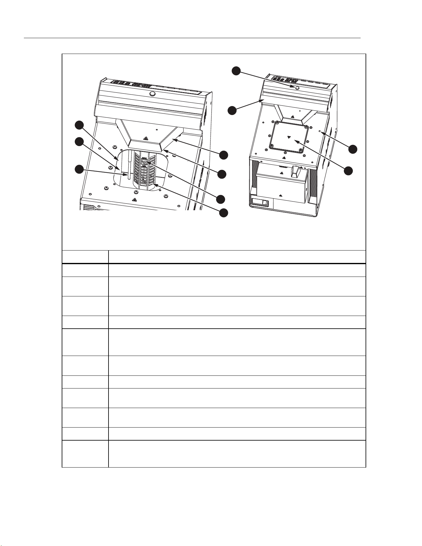
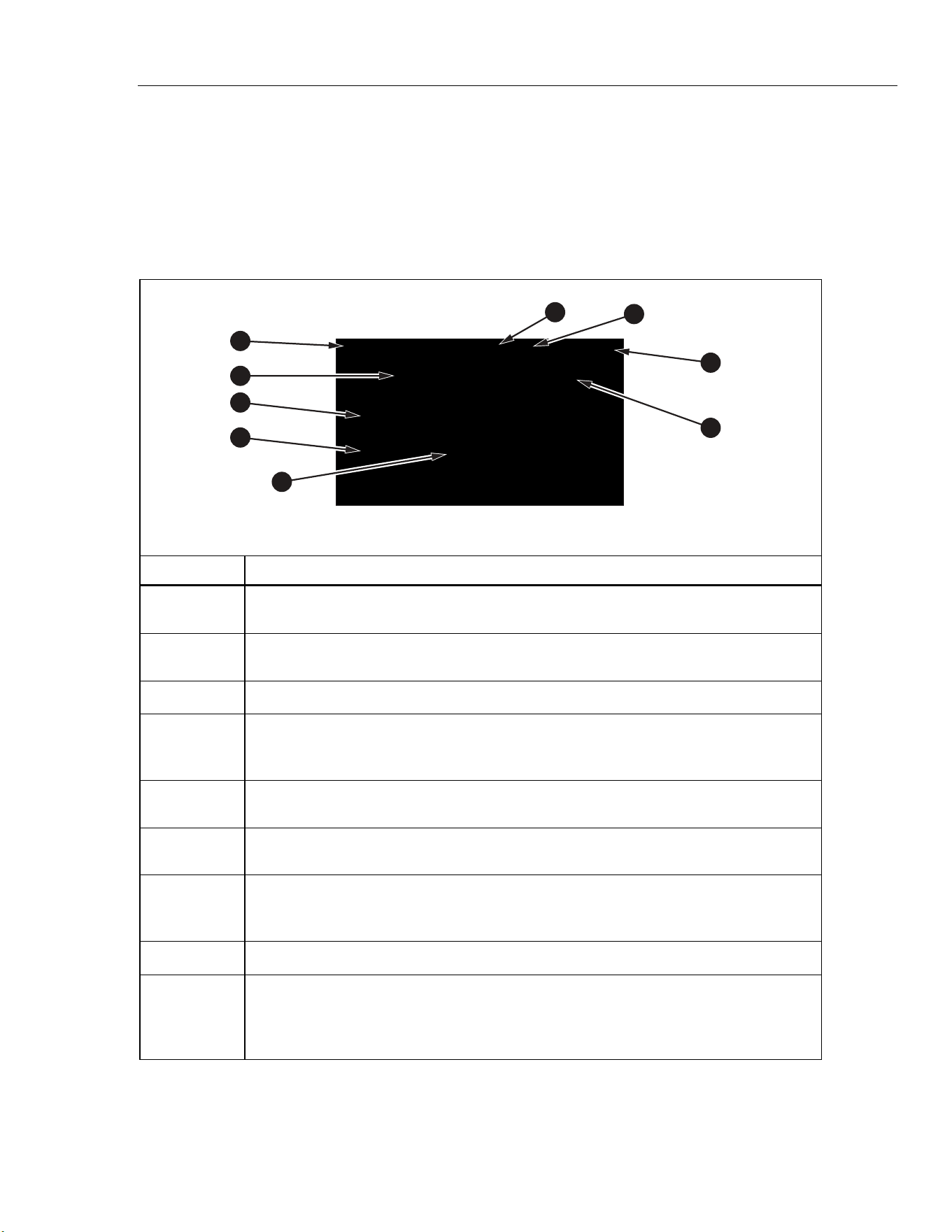
Top
The Product top and tank are shown in Figure 1.
1.888.610.7664 sales@GlobalTestSupply.com
Fluke-Direct.com
6109A/7109A
Operators Manual
8
4
9
8
10
11
1
2
3
5
6
7
icu07.eps
Number Description
Tank - The stainless steel tank contains the bath fluid.
Bath Fluid - Temperature sensors are inserted into the bath fluid for calibration. Heating
and cooling devices attached to the walls of the tank heat and cool the bath fluid.
Control Sensor - The precision platinum resistance thermometer (PRT) measures and
controls the temperature of the bath fluid.
Stir Motor Cover - Protects the stir motor.
Stir Motor (under the Stir Motor cover) - The stir motor drives the propeller that circulates
the fluid to produce a uniform temperature. The stir motor turns on when control is
enabled.
Stir Guard - Separates the working area of the tank from the stir propeller. MIN and MAX
marks on the stir guard show the correct fill levels.
Propeller - Stirs the bath fluid.
Carrying Handle - Use the handle to lift or move the Product. There are also recessed
handles on the sides of the Product (not shown).
Ready Indicator - Changes from amber to green when the bath fluid temperature has
settled at the setpoint. Green indicates that the Product is ready for measurement.
Threaded Holes (M4) - Used to attach accessories to the Product.
Tank Cover - Isolates the bath fluid from the environment, reduces fumes, prevents
objects from falling into the tank, and keeps the fluid temperature stable. The tank cover
attaches to the top panel with four thumb screws.
Figure 1. Top of the Product
1.888.610.7664 sales@GlobalTestSupply.com
Fluke-Direct.com
Portable Calibration Baths
Product Overview
9
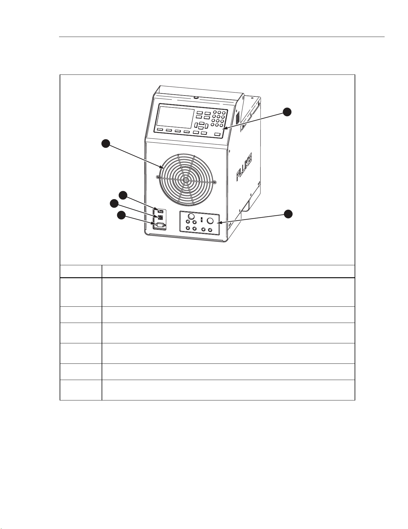
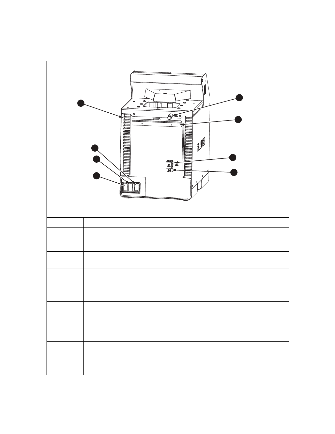
Front
The front of the Product is shown in Figure 2.
5
1
2
4
6
3
icu01.eps
Number Description
Fan - Cools the tank and heating devices. Keep at least 150 mm of open space around the
Product and 300 mm behind it to avoid obstruction of the air flow. Keep objects away from
the fan opening as the fan produces strong suction.
USB Host Port - Use this port to record temperature data to a memory device.
USB Device Port - Like the RS-232 Port, this USB device port can be used to control the
Product.
RS-232 Port - Like the USB Device Port, this port can be used to control the Product
remotely.
Control Panel - See Control Panel.
Process Input Module - This optional module measures electrical temperature sensors for
calibration.
Figure 2. Front of the Product
1.888.610.7664 sales@GlobalTestSupply.com
Fluke-Direct.com
6109A/7109A
Operators Manual
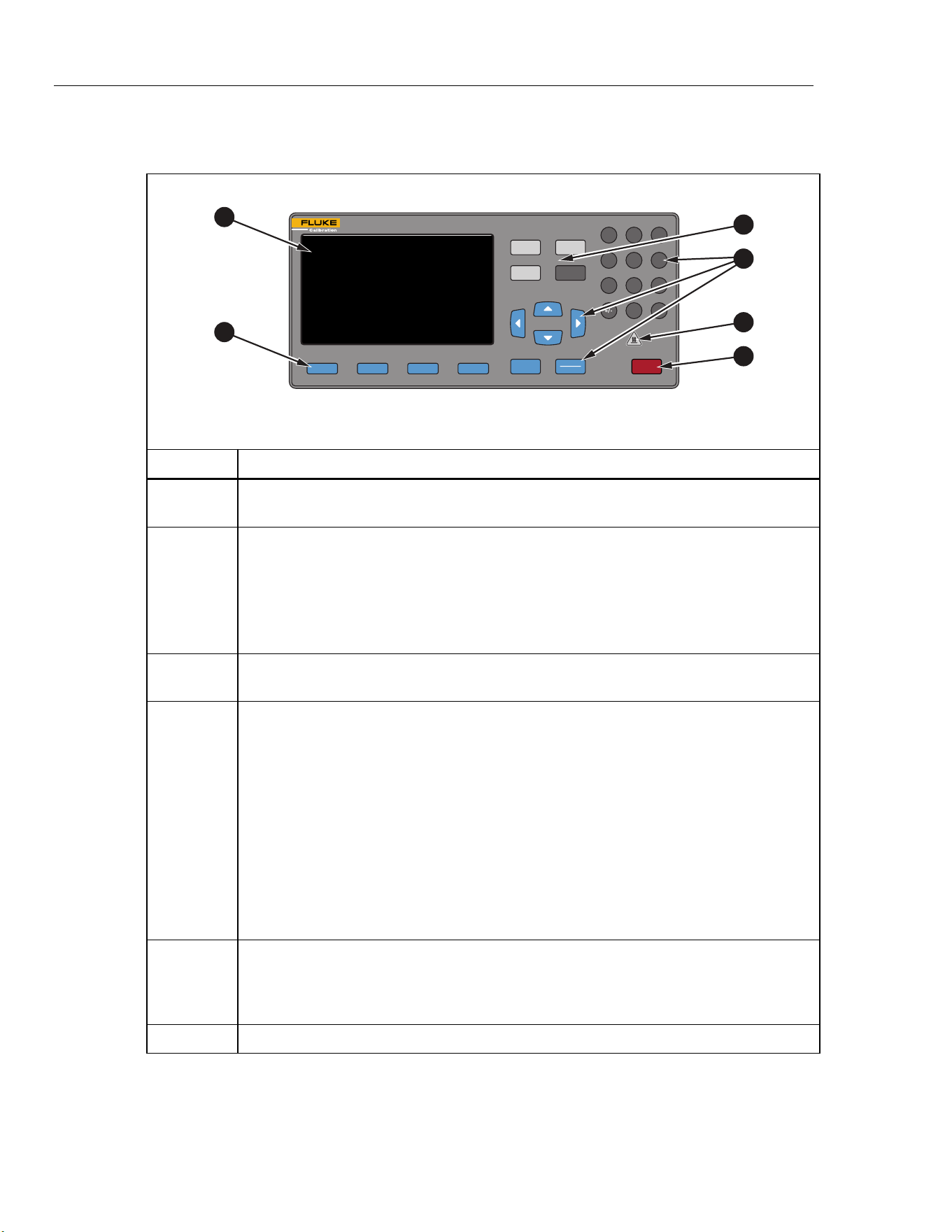
10
Control Panel
The control panel is shown in Figure 3.
F1 F2 F3 F4
BACK
PROGRAM
SETPOINT
1 3
46
2
5
798
0
.
STOP
SELECT
ENTER
MONITOR
SETUP
PORTABLE CALIBRATION BATH
6109A
35°C TO 250°C
1
2
3
5
6
4
icu05.eps
Number Description
Display - Shows the information about the operation of the Product such as the fluid
temperature and setpoint.
Softkeys - These keys correspond to the display icons directly above each key. The
functions change with the status of the display. In many menus is labeled Done.
It returns the screen to the first menu.
As you type numbers for settings, acts as a backspace key. This deletes the last
digit in the number. If a setting accepts a number in exponential notation, works
as an exponent key.
Mode Keys - , , , and access different groups of settings. Some
mode keys light up when the mode is active.
Other Keys - Controls used to operate the Product. There are numbers, cursor keys,
and to make menu choices.
- Returns the UI to the prior menu.
and - Use to move the cursor up or down.
and - Use to move the cursor left or right.
Number keys (0-9) - Use the ten number keys to enter decimal numbers. If a setting
accepts an exponential number, a special exponent key is shown as one of the softkeys.
Push to save the number.
- Change a selected item. After the setting is changed, push to save the new
value. Settings that have only binary states, such as ON or OFF, are changed and
saved with a single push.
Hot Warning Indicator - This indicator lights up if the fluid temperature is ≥60 °C. This
warns that the bath fluid, tank cover, and area around the tank are hot and should not
be touched. If the Product is switched off, the indicator stays on until the Product
reaches a safe temperature. It flashes at a slow rate to conserve energy.
- Immediately disables heating and cooling and switches off the stir motor.
Figure 3. Control Panel
1.888.610.7664 sales@GlobalTestSupply.com
Fluke-Direct.com
Portable Calibration Baths
Product Overview
11
Back
The back of the Product is shown in Figure 4.
5
1
2
3
4
6
7
8
icu09.eps
Number Description
Fan Vents - As the Product cools, a heavy air stream flows from the fan vents. Keep at
least 300 mm of open space behind the Product to avoid an obstructed air flow. There
are also ventilation slots on the sides of the Product (not shown).
Mains Power Socket - A grounded male three-prong connector that accepts the mains
power cord. Connect the Mains power cord here.
Power Switch - Toggle this switch to I to turn on the Product. Toggle this switch to O to
turn off the Product.
Fuses - Protect the Product from excessive current. If a fuse appears to be blown,
contact Fluke Calibration for assistance. See Contact Fluke Calibration.
Overflow Tube - Directs excess bath fluid into the optional overflow container. If the
overflow kit is not used, keep the overflow tube plugged and reduce the fluid level to
allow for thermal expansion.
Overflow Container Mounting Bracket – Holds the optional overflow container (not
shown).
Drain Cover - Keep the drain plug (not shown) on tight and the drain cover in place for
normal operation.
Drain Tube - The drain tube (not visible) makes it easy to remove the bath fluid for
replacement or Product transport.
Figure 4. Back of the Product
1.888.610.7664 sales@GlobalTestSupply.com
Fluke-Direct.com
6109A/7109A
Operators Manual
12
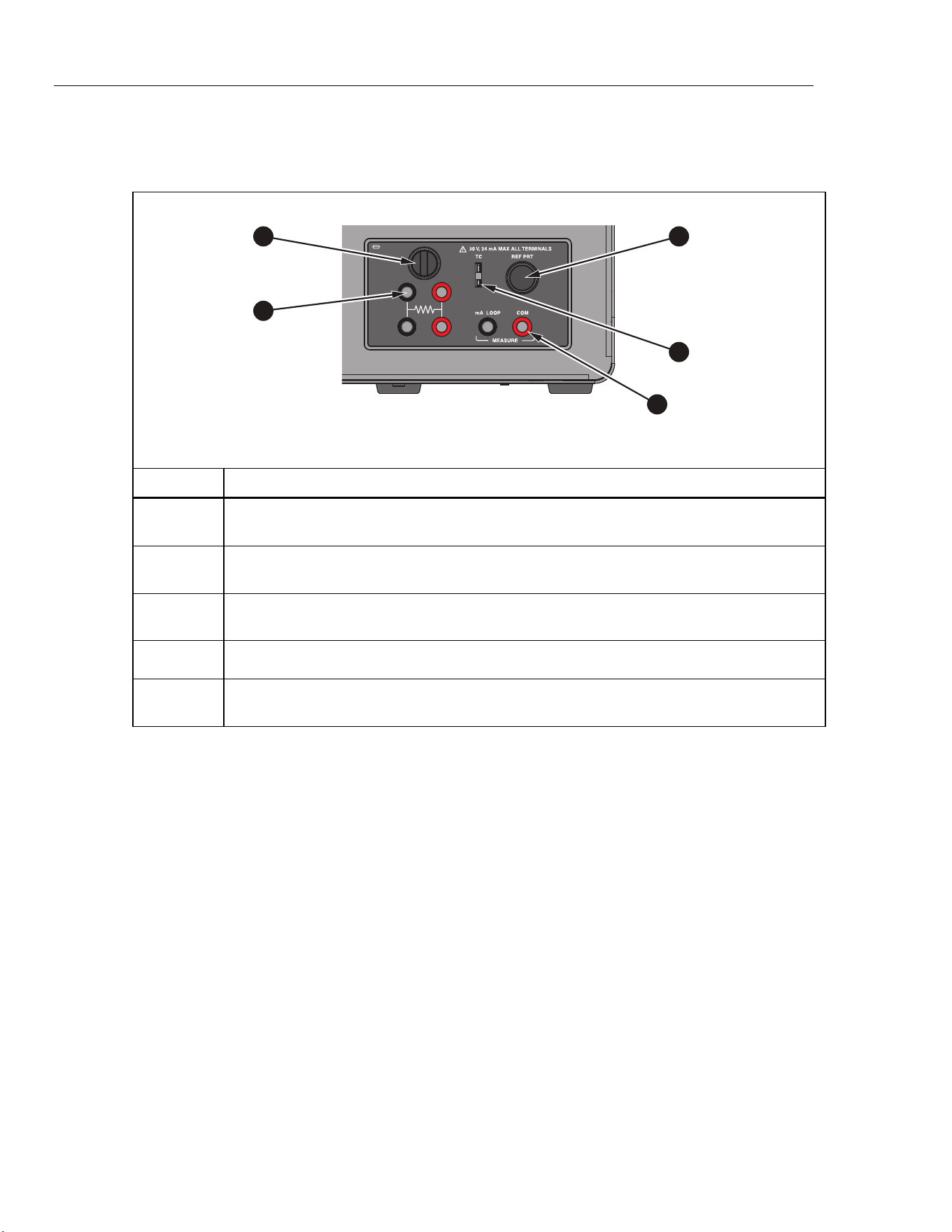
Input Module (Option)
The 7109A-P and 6109A-P come with an Input Module that measures various
types of temperature sensors. This optional input module is shown in Figure 5.
F 50 mA 250V
3
1
2
4
5
icu02.eps
Number Description
Current Fuse - Protects the Input Module and connected devices from accidental short
circuit. Replace the fuse only with the same type: 5 mm × 20 mm, 50 mA, fast-acting.
RTD Terminals - A test RTD connects to these terminals. The graphic on the panel shows
the circuit diagram for a four-wire RTD.
Reference PRT Connector - A reference probe plugs into this socket. The connector
accepts a Fluke INFO-CON plug with a memory device that stores probe coefficients.
Thermocouple Input - A miniature thermocouple connector.
Transmitter Terminals - A 4-20 mA transmitter connects to the two transmitter terminals
labeled mA LOOP and COM.
Figure 5. Input Module Option
Installation
The subsequent sections explain safe and correct Product installation.
Product Placement
Warnings
To prevent possible electrical shock, fire, or personal injury, do
not restrict access to the Product mains power cord. The mains
power cord is the mains disconnecting device.
Place the unpacked Product on a clean, sturdy, flat surface in a spacious location
with good environmental control. There must be at least 150 mm (6 inches) of
space around the front and sides and 300 mm of open space behind the Product
for the ventilation and cooling fans to operate properly. The environment must
maintain a steady, moderate temperature and dissipate up to 1000 W of heat
produced by the Product. Avoid air drafts and temperature fluctuations that could
adversely affect the temperature stability of the Product.
1.888.610.7664 sales@GlobalTestSupply.com
Fluke-Direct.com

Portable Calibration Baths
Installation
13
Provide Ventilation
Warning
To prevent personal injury:
• Read the bath fluid safety data sheet (SDS) and take
necessary precautions. Some fluids are corrosive, toxic, or
irritate the skin, eyes, nose, and respiratory organs.
• Use a ventilation system to remove vapor.
• Do not use fluids that are corrosive to stainless steel.
Harmful substances such as benzene and formaldehyde can be produced above
a certain temperature. The safety data sheet for a silicone fluid typically states
149 °C for this temperature.
Bath fluid vapors present a fire hazard, especially when the bath fluid is operated
above its flash point. Bath fluid vapors tend to condense onto surrounding
surfaces. This can contaminate materials and inhibit laboratory cleanliness. If
enough condensation accumulates on the floor, the floor becomes slippery and
creates a safety hazard.
For appropriate fume extraction use a ventilation duct of at least 75 mm
(3 inches) in diameter with an air flow rate between 1.4 cubic meters and
1.7 cubic meters per minute (50 cfm to 60 cfm). Place the inlet of the ventilation
duct near the top of the tank.
Add Bath Fluid
The choice of bath fluid is important for the Product to achieve full temperature
range and performance specifications. Table 2 lists the recommended bath fluid
for each model.
Table 2. Recommended Bath Fluids
7109A 6109A
Fluke 5012 Silicone, 10 centistoke Fluke 5014 Silicone, 50 centistoke
1.888.610.7664 sales@GlobalTestSupply.com
Fluke-Direct.com

6109A/7109A
Operators Manual
14
Other bath fluids can be used, but the temperature range may be more limited.
Temperature stability and uniformity also varies when other fluids are used. As a
rule, bath fluid viscosity should be no greater than 50 centistokes at any
operating temperature. See Fluid Selection for more information.
Silicone fluid expands as it is heated. This can cause the bath fluid to spill out of
the tank. Use the optional overflow kit or fill the tank to a lower level. The stir
guard has marks MAX and MIN to show the proper fill levels. Fill the tank to the
MIN level if the plug is left in the overflow tube. Fill to the MAX level if the
overflow kit is used. Table 3 gives the recommended fill levels as measured from
the bottom of the tank.
Table 3. Fluid Fill Levels
Overflow Kit Installed Overflow Tube Plugged
MAX level, 154 mm MIN level, 128 mm
Note
Remove the plug from the overflow tube if the tank is filled to
maximum depth.
To add bath fluid:
1. Remove the tank cover.
2. Pour the bath fluid in through the tank opening.
3. Replace the cover and tighten its thumb screws.
4. Clean up any drips or spills. Do not get fluid on the control panel.
Attach the Probe Access Cover
Keep the tank covered when you operate the Product to ensure temperature
stability, uniformity, and accuracy. Use the provided probe access cover. The
cover holes fit many types of temperature sensors. Use the thumb screws to
fasten the cover to the top panel. Make sure the rubber gasket is properly
seated.
Connect to Mains Power
Warning
To prevent possible electrical shock, fire, or personal injury,
connect the factory-supplied three-conductor mains power cord
to a properly-grounded power outlet. Do not use a two-
conductor adapter or extension cord, as it will break the
protective ground connection.
Use the provided mains power cord to connect the Product to a 150 V ac or
230 V ac outlet (this depends on the model). The circuit, outlet, and mains power
cord must all be rated at 115 V ac, 10 A at 230 V ac.
1.888.610.7664 sales@GlobalTestSupply.com
Fluke-Direct.com
Portable Calibration Baths
Installation
15
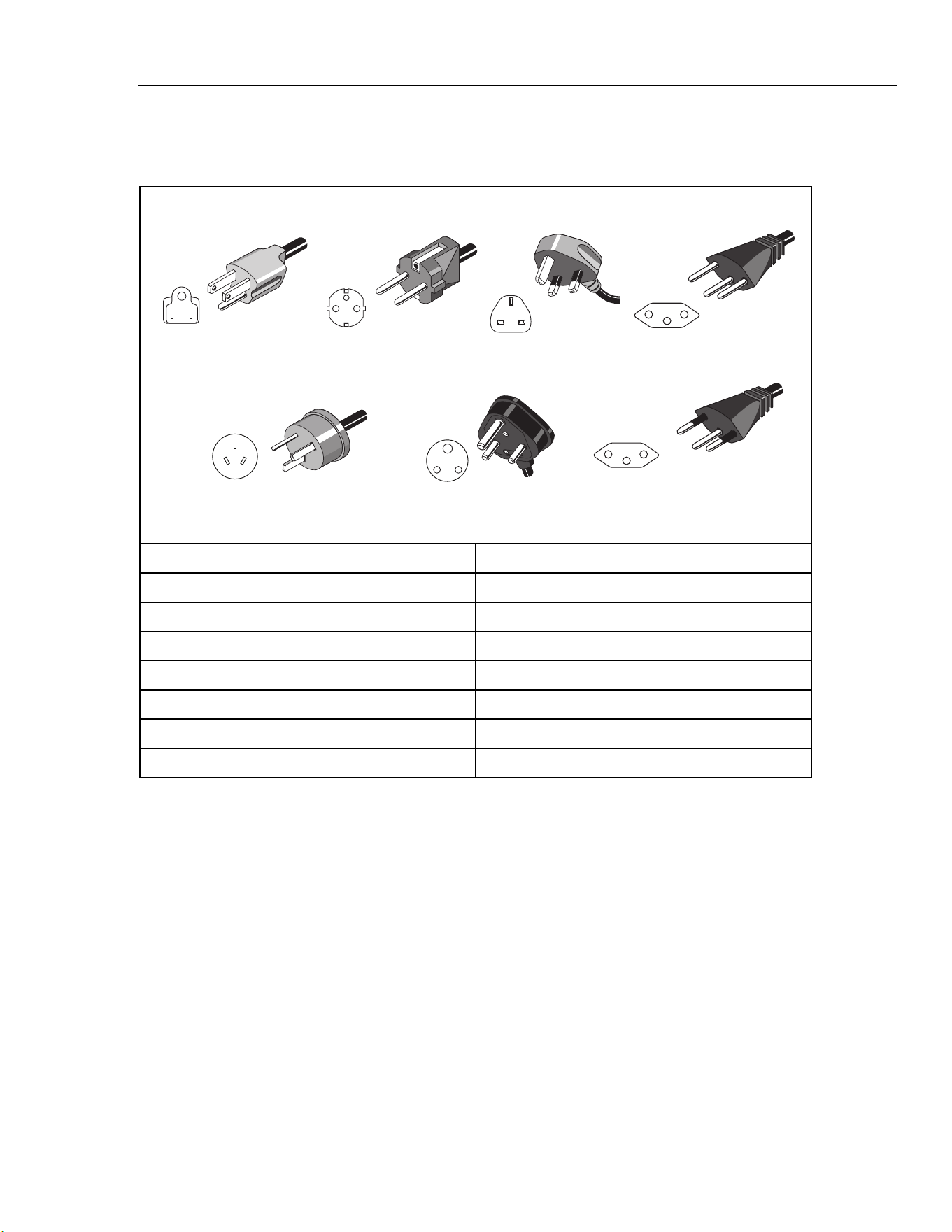
The Product comes with the appropriate line power plug for the country of
purchase. If a different type is necessary, refer to Figure 6 for the correct mains
line power plug types available from Fluke Calibration.
Universal EuroNorth American/Japan United Kingdom
Australia/China
Swiss
South Africa Brazil
LC-1
LC-3
LC-4
LC-5
LC-6
LC-7 LC-42
hhp004.eps
Type Fluke Calibration Part Number
North America LC-1
Universal Euro LC-3
United Kingdom LC-4
Switzerland LC-5
Australia LC-6
South Africa LC-7
Brazil LC-42
Figure 6. Available Mains Power Cord Types
1.888.610.7664 sales@GlobalTestSupply.com
Fluke-Direct.com
6109A/7109A
Operators Manual
16
Attach Accessories
Accessory attachment is explained in the subsequent sections.
Fluid Overflow Accessory
Fluke Calibration recommends the fluid overflow accessory kit (model 7109-
2083) to avoid spills caused by thermal expansion of the fluid or an overfilled
tank.
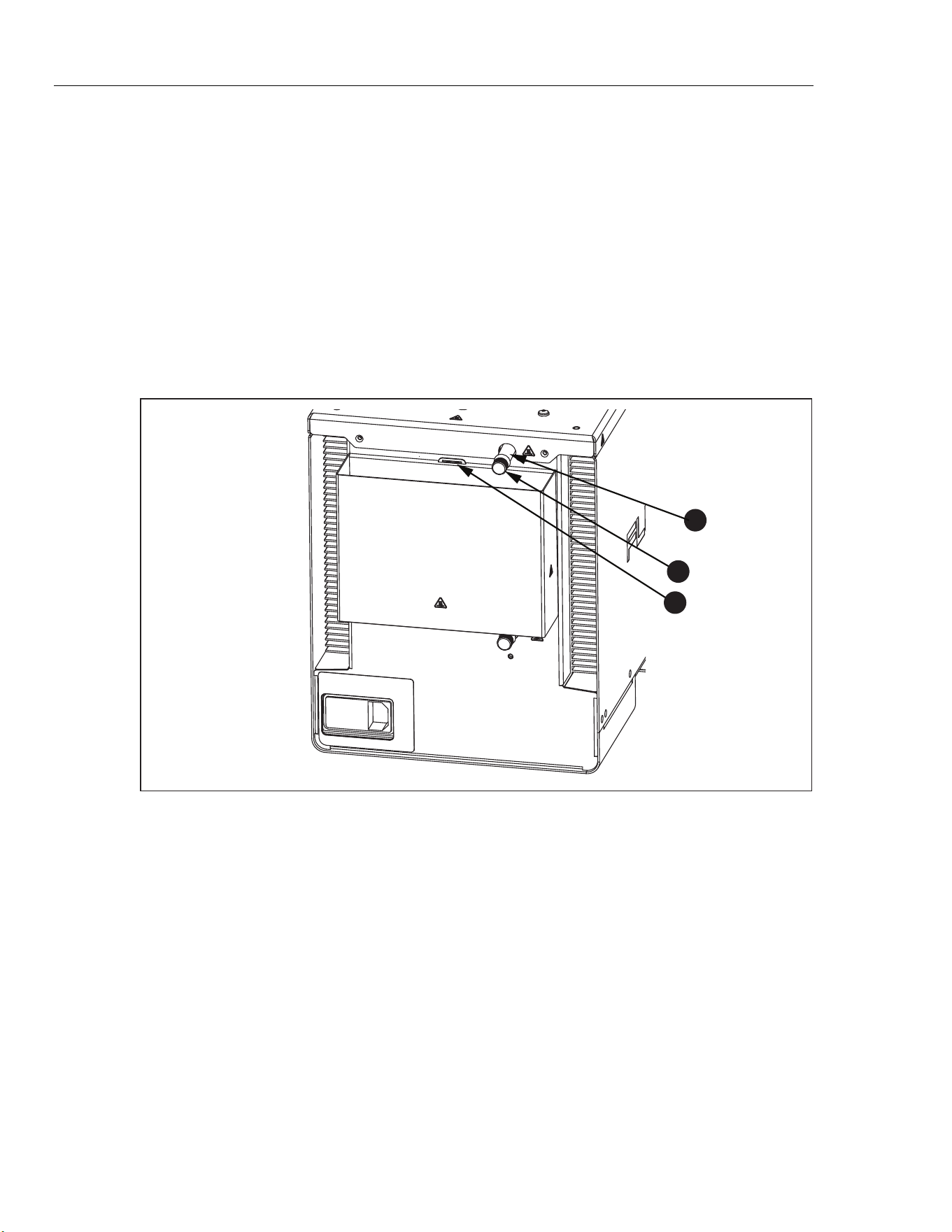
To install the bath fluid overflow accessory, see Figure 7:
1. Remove the plug from the overflow tube .
2. Place the overflow container onto the mounting bracket and align it below
the overflow tube.
3. Place the cover (not shown) on the overflow container.
1
2
3
icu03.eps
Figure 7. Fluid Overflow Accessory
1.888.610.7664 sales@GlobalTestSupply.com
Fluke-Direct.com
Portable Calibration Baths
Installation
17
Probe Clamp
Use the probe clamp accessory (Model 7109-2051, purchased separately) to
hold temperature probes in place while they are calibrated. The post of the probe
clamp screws into any of the four the M4 size threaded holes located near the
corners of the top panel. See Figure 8.
icu14.eps
Figure 8. Probe Clamp Accessory
1.888.610.7664 sales@GlobalTestSupply.com
Fluke-Direct.com
6109A/7109A
Operators Manual
18
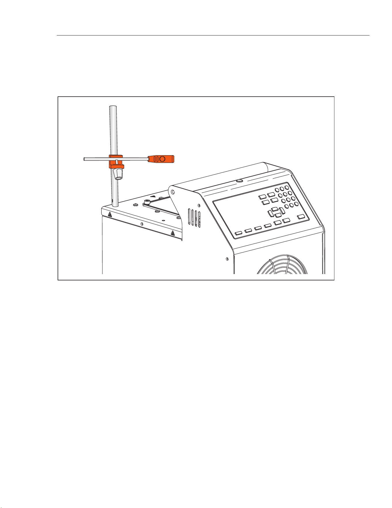
Adjustable Probe Fixture
Use the adjustable probe fixture (model 7109-2027) to hold up to four tri-clamp
temperature sensors. The device fits inside the tank opening and attaches to the
top panel of the Product with four thumb screws. The height of the platform can
be adjusted for proper immersion of the stems and flanges of the temperature
sensors. To adjust the height, slightly squeeze the tabs inward on the height
adjustment bracket shown in Figure 9.
1
icu08.eps
Figure 9. Adjustable Probe Fixture
1.888.610.7664 sales@GlobalTestSupply.com
Fluke-Direct.com

Portable Calibration Baths
Turn On the Product
19
Turn On the Product
Push the power switch on the back panel of the Product to the I side to turn on
the Product. The Product can take up to 40 seconds for the Product to become
fully operational.
Set the Language, Time, and Date
Set the display language, time, date, and other operator preferences in the Setup
Instrument screen. The UI is available in:
• English
• French
• German
• Portuguese
• Spanish
• Russian
• Simplified Chinese
• Japanese
• Korean
To change the language, time, or date:
1. Push .
2. Push .
3. Push to move the focus to an item.
4. Push .
5. Push to move the selection to the necessary value.
6. Push to save the change.
7. Push the (Done) to return to the first screen.
1.888.610.7664 sales@GlobalTestSupply.com
Fluke-Direct.com

6109A/7109A
Operators Manual
20
Set the Password
The Product ships from Fluke Calibration with minimal security settings. Except
for calibration parameters, any settings are easily changed.
To change the security level and set a new password to prevent unauthorized
use:
1. Push .
2. Push .
3. Push (More).
4. Push (Password).
5. Use the number keys to type in the factory password 1234.
6. Push to access the Password screen.
7. Push to edit the password.
8. Use the number keys to type in a new password.
9. Push save the new password.
10. Push to move to the Security setting.
11. Push to change the security level.
12. Push (Done) to return the first screen.
Note
Make sure to save the new password and do not lose it.
Connect the Reference Probe and Test Sensor
The 7109A-P and 6109A-P include the Input module to which a reference
thermometer and one DUT (Device Under Test) sensor can be connected.
Temperatures show on the display and are automatically recorded as a program
runs. This section explains how to set up these models to operate the sensor
inputs.
Connect the Reference Probe
A reference probe provides improved temperature accuracy and serves as a
reference standard to test other sensors. For best results, use a high-quality,
100 Ω, four-wire, platinum resistance thermometer (PRT) calibrated with low
uncertainty such as Fluke 5615-6. Table 4 shows how a reference probe can be
used to improve temperature accuracy.
Table 4. Typical Accuracy with a Fluke 5615 as a Reference Probe
Temperature Expanded Uncertainty (k = 2)
-25 °C 0.020 °C
0 °C 0.022 °C
140 °C 0.031 °C
250 °C 0.043 °C
1.888.610.7664 sales@GlobalTestSupply.com
Fluke-Direct.com
Portable Calibration Baths
Connect the Reference Probe and Test Sensor
21
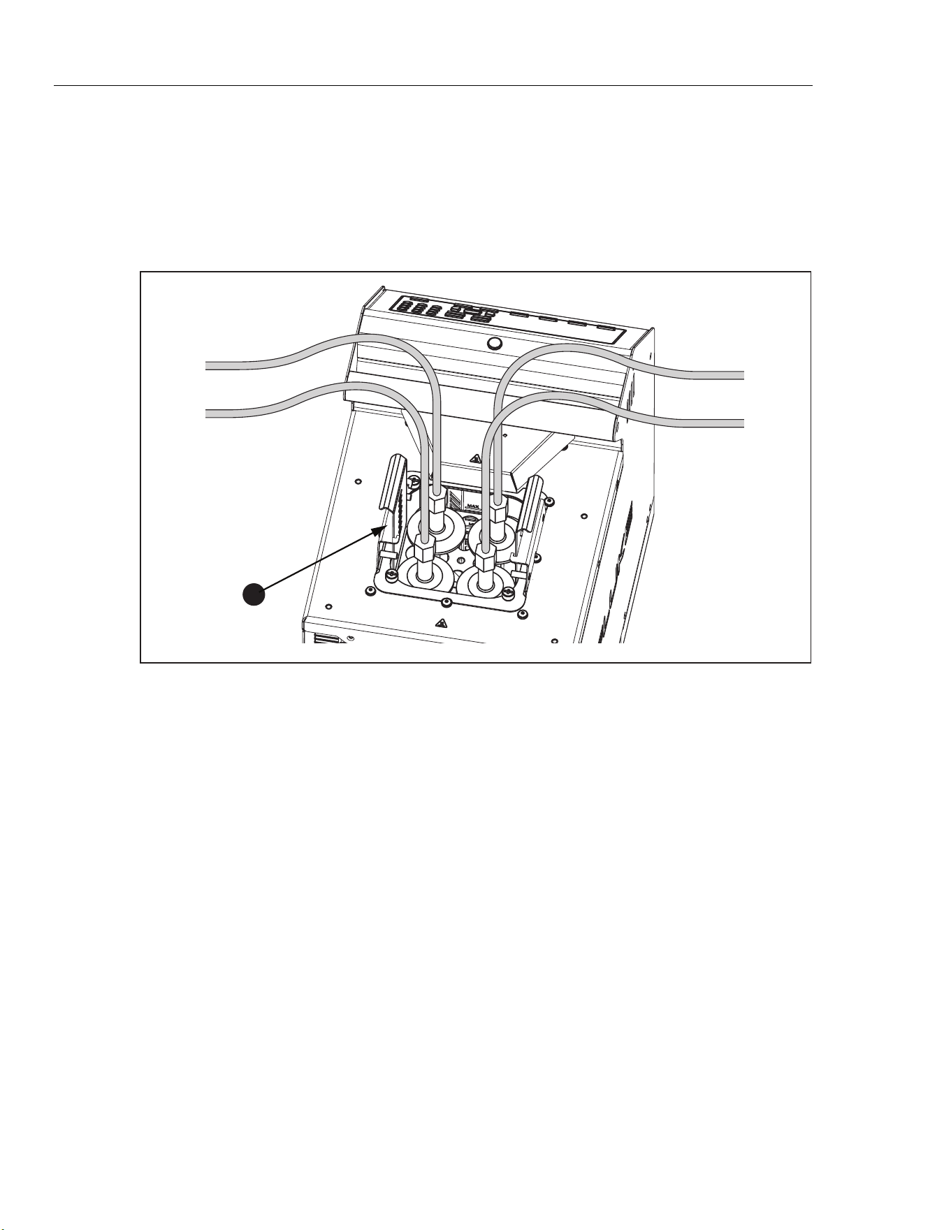
Use the provided clamp-on ferrites to reduce radio-frequency emissions and to
ensure electromagnetic compatibility with other equipment. Loop a section of
cable near the connector through the ferrite as shown in Figure 10. Fluke
Calibration also recommends a ferrite for the test sensor.
1
3
2
icu10.eps
Number Description
Connector
Clamp-on Ferrite
Probe
Figure 10. Ferrite Installation
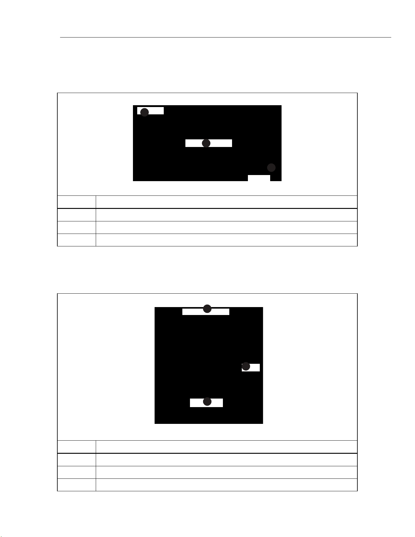
The reference probe plugs into the REF PRT input. It requires a 6-pin DIN
connector wired as shown in Figure 11.
1
2
3
icu11.eps
Number Description
Probe Connector
Shield
PRT Sensor
Figure 11. Reference Probe Connections
1.888.610.7664 sales@GlobalTestSupply.com
Fluke-Direct.com
6109A/7109A
Operators Manual
22
Configure the Reference Probe Coefficients
Probe coefficients must be configured for the PRT temperature to be accurately
measured. If the reference probe has a properly-programmed INFO-CON
connector, probe coefficients are automatically configured when the probe is
connected to the Product. The connection icon shows at the top of the display to
show that the probe coefficients were successfully transferred from the
connector. To view the probe coefficients and verify that they are correct, go to
the Reference Probe menu:
1. Push .
2. Push (Probe Function).
3. Push (Reference Probe).
4. Push or to step through the list.
5. Push (Done) to return the first screen.
If the reference probe does not have a programmed INFO-CON connector, enter
the probe coefficients manually. Get the values from the reference PRT’s report
of calibration. Push (Test Calculation) to test the probe coefficients and
see that they produce correct temperatures.
When properly connected and configured, the temperature of the reference
probe shows on the display under Reference in Monitor mode.
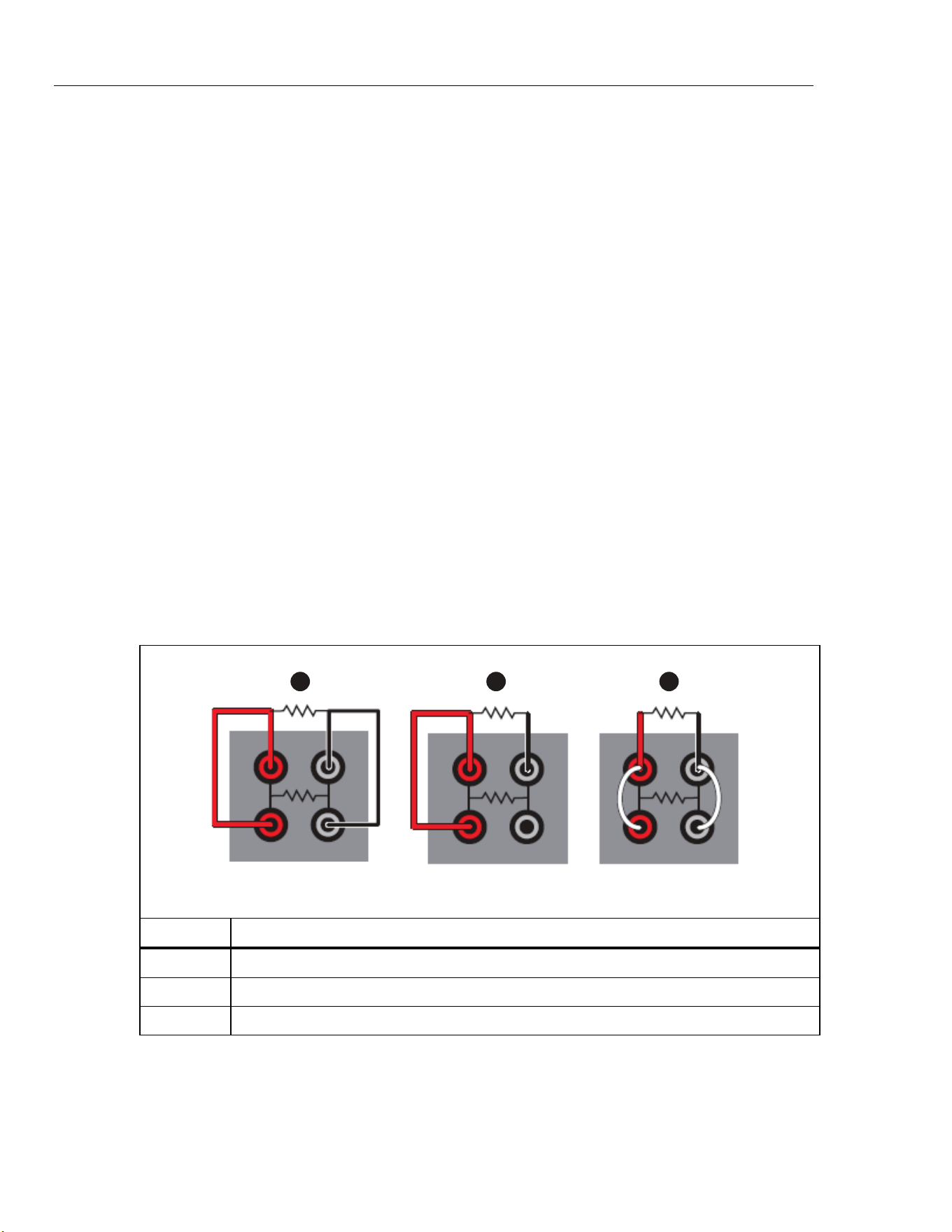
Connect a Test RTD
The Input Module measures the resistance of a four-wire, three-wire, or two-wire
RTD. The RTD connects to the set of four banana terminals on the Input Module.
See Figure 12.
1 2 3
icu12.eps
Number Description
4-wire RTD
3-wire RTD
2-wire RTD
Figure 12. Test RTD Connections
1.888.610.7664 sales@GlobalTestSupply.com
Fluke-Direct.com

Portable Calibration Baths
Connect the Reference Probe and Test Sensor
23
Configure the RTD Type
To configure the test RTD to accurately measure the temperature or the
resistance of the RTD:
1. Push .
2. Push (Probe).
3. Push (DUT).
4. Push to edit the DUT Type.
5. Push or to move the highlight to RTD.
6. Push to save the DUT Type.
7. Push to move the highlight to the Wires control.
8. Push to enter edit mode.
9. Push or to move the highlight to the correct number of wires.
10. Push to save.
11. Push to move the highlight to the RTD Type control.
12. Push to enter edit mode.
13. Push or to move the highlight to the correct type.
14. Push to save.
15. Push (Done) to return the first screen.
When properly connected and configured, the temperature or resistance of the
test RTD shows on the display under DUT in Monitor mode.
Connect a Thermocouple
The Input Module measures temperature from a thermocouple and automatically
applies reference junction compensation. The thermocouple connects directly to
the miniature thermocouple connector labeled TC. Do not use an external
reference junction. The positive wire connects to the smaller blade of the
connector.
1.888.610.7664 sales@GlobalTestSupply.com
Fluke-Direct.com

6109A/7109A
Operators Manual
24
Configure the Thermocouple Type
To configure the thermocouple type to measure the temperature of the
thermocouple accurately:
1. Push .
2. Push (Probe).
3. Push (DUT).
4. Push to edit the DUT type.
5. Push or to move the highlight to the Thermocouple control.
6. Push to save the DUT Type.
7. Push to move the highlight to the Thermocouple Type control.
8. Push to enter edit mode.
9. Push or to move the highlight to the correct type.
10. Push to save.
11. Push (Done) to return the first screen.
When properly connected and configured, the temperature of the thermocouple
shows on the display under DUT in Monitor mode.
Connect a 4–20 mA Transmitter
The Input Module measures current from a 4–20 mA loop transmitter. The Input
Module also provides dc voltage to power the transmitter. The transmitter wires
connect to the two banana terminals labeled mA LOOP and COM. If Loop Power
mode is OFF, the Input Module measures current that flows into the red COM
terminal. If Loop Power is on, positive dc voltage is supplied from the red COM
terminal to the black mA LOOP terminal, and the Input Module measures current
that flows into the black mA LOOP terminal.
Configure the mA Input
Configure the Input Module to measure the transmitter current. If the transmitter
has a separate power supply, set Loop Power to OFF. If the Product must supply
power to the transmitter, set Loop Power to ON.
1. Push .
2. Push (Probe).
3. Push (DUT).
4. Push to edit the DUT type.
5. Push or to move the highlight to the mA control.
6. Push to save the DUT Type.
7. Push to move the highlight to the Loop Power control.
8. Push to switch Loop Power ON or OFF.
9. Push (Done) to return the first screen.
Use the Offset, Span, and Unit settings to convert the transmitter measurement
to another unit such as temperature.
When properly connected and configured, readings from the transmitter show on
the display under DUT in Monitor mode.
1.888.610.7664 sales@GlobalTestSupply.com
Fluke-Direct.com
Portable Calibration Baths
Operation
25
Operation
This section explains how to operate the Product after it is set up.
The user interface (UI) and basic key actions are explained in the subsequent
sections.
Display
The display is explained in Figure 13.
1
2
3
4
5
9
6
8
7
icu06.eps
Number Description
Date and Time - The present date and time from the internal, battery-operated clock of
the Product.
Bath Fluid Temperature - The temperature of the bath fluid as measured by the internal
control sensor.
Setpoint - The Product heats or cools to maintain the fluid temperature at the setpoint.
Reference Temperature (-P models only) - If sensors are connected to the input
module and are properly configured, the reference temperature and test sensor reading
show on the home screen.
Test Sensor reading (-P models only) - This is the temperature that the DUT presently
reads.
Control Indicator - Shows Stable when the bath fluid temperature is at the setpoint and
the Product is ready for temperature measurement.
Connection Indicator (-P models only) - The connection indicator shows when a
reference probe is connected and its probe coefficients have successfully been
transferred to the Product.
Recording Indicator - Shows when recording is on.
Heating Status - Shows these states: Off, Heating, Cooling, or Cutout. Cutout indicates
that the bath fluid temperature has exceeded the cutout temperature setting.
Temperature control can only resume after you push and the bath fluid cools
below the cutout temperature.
Figure 13. The Display
1.888.610.7664 sales@GlobalTestSupply.com
Fluke-Direct.com

6109A/7109A
Operators Manual
26
Basic Operations
Common operations are explained in the subsequent sections.
Immerse Temperature Probes
For best results:
• Check that the bath fluid level is between the MIN and MAX marks on the stir
guard.
• See that the bath fluid stirs well when you enable temperature control.
• Keep the bath fluid covered as much as possible to ensure good temperature
stability and uniformity and to reduce fumes. Use the provided probe access
cover or a custom cover.
• Immerse sensors in the bath fluid so that the tips of the probes are at least
15 mm above the bottom of the tank and 65 mm below the surface of the
fluid. When you test the tri-clamp temperature sensors, immerse their flanges
just below the surface of the bath fluid to ensure good thermal equilibration of
the temperature sensor with the bath fluid.
• If you use a reference probe, place it in the center of the working area.
• Use the optional probe clamps to hold sensors vertical at the proper height.
Set the Setpoint
1. Push . The setpoint field changes to edit mode.
2. Enter the setpoint temperature with the number keys.
3. Push to save the setpoint.
4. Push (Ramp) to specify a temperature ramp rate.
5. Push to edit the Ramp Rate.
6. Use the number keys to type a rate (in °C or °F per minute).
7. Push to save the new value.
8. Push to move the focus to Ramp Enable.
9. Push to enable the ramp rate.
10. Push (Done).
11. Push or the Enable softkey to heat or cool the bath fluid to the setpoint.
If ramp rate is enabled, the rate of change is controlled until the temperature
reaches the setpoint. The Product may reduce heating power as it approaches
the setpoint to minimize overshoot.
When the temperature reaches the setpoint, the control indicator changes to
Stable and the ready indicator turns green. The temperatures of the sensors can
then be measured and compared.
1.888.610.7664 sales@GlobalTestSupply.com
Fluke-Direct.com

Portable Calibration Baths
Operation
27
Preset Setpoints
Use presets to set the setpoint to frequently-used temperatures. To define
presets:
1. Push .
2. Push (Presets) to see the list of preset setpoints.
3. Push as needed to choose one of the numbered setpoints.
4. Push (Edit) to edit the setpoint.
5. Use the number keys to type temperature.
6. Push to save the new value.
7. Push (Done) after all presets have been defined.
To recall a preset:
1. Push .
2. Push (Presets) to see the list of preset setpoints,
3. Push as needed to choose one of the numbered setpoints.
4. Push to activate the chosen preset. The Setpoint field on the display
shows that the setpoint has changed to match the selected preset.
Set the Cutout
The cutout is a safety device that prevents overheating of the Product and bath
fluid in the event of operator error or product malfunction. For each test, set the
cutout to 5 °C to 15 °C above the maximum temperature at which the Product will
operate. Do not set the cutout higher than the maximum safe temperature of the
fluid.
1. Push .
2. Push (Operation).
3. Push to edit the Cutout Temperature.
4. Use the number keys to type in a temperature.
5. Push to save the new temperature.
Stop Heating or Cooling
Push to turn off heating and cooling and the stir motor.
Select the Temperature Unit
To change the temperature to degrees Fahrenheit or degrees Celsius:
1. Push .
2. Push (Operation).
3. Push (°C or °F).
4. Push to see temperatures in the selected unit of measurement.
Note
In some regions, the Product may not have this option.
1.888.610.7664 sales@GlobalTestSupply.com
Fluke-Direct.com

6109A/7109A
Operators Manual
28
Control the Bath Temperature with a Reference Probe
The 7109A-P and 6109A-P allow measurements from the reference probe to be
used to control the fluid temperature with more accuracy. Set up the reference as
explained in Configure the Reference Probe Coefficients.
1. Push .
2. Push (Operation).
3. Push several times to move the highlight to Control Sensor.
4. Push to switch the value to Reference.
5. Push to view the control temperature.
When the reference probe controls temperature, the display shows the fluid
temperature in gray and the Reference temperature in black.
When the reference probe is used, the settling time and temperature variation
may be slightly greater.
Keyboard Use
Use the keyboard to enter or change filename characters. To use the keyboard:
1. Use the direction keys to choose a letter.
2. Push to add the letter to the filename.
3. Repeat until the filename is complete. Push (Backspace) to delete a
letter.
Recording Temperature
The recording function stores temperature readings in a file on a USB memory
device. To use this device:
1. Insert a Linux-compatible, FAT32-formatted memory device into the USB
host port on the front panel.
2. Wait for the device to be recognized.
3. Push .
4. Push (Recording).
5. Push (Filename).
6. Push to specify the filename.
7. Push (Save) to save the filename. See Keyboard Use.
8. Push (Start Recording) to record temperature. Observe that the
recording icon shows at the top of the display.
9. Push (Stop Recording) to stop recording.
10. Wait at least 5 seconds after you stop recording before you remove the USB
memory device. This allows time for all the data to be written and the file
closed.
1.888.610.7664 sales@GlobalTestSupply.com
Fluke-Direct.com

Portable Calibration Baths
Operation
29
The extension “.txt” is automatically appended to the filename when the file is
created. If the file already exists, new data is appended to the end of the file. The
file is placed in a folder determined by the serial number of the Product:
\Fluke\7109_6109\<product serial number>\Data\
Each line in the file contains the date and time, fluid temperature, its unit of
measurement, reference probe reading, its unit of measurement, DUT reading,
and its unit of measurement. Fields are separated by commas. If reference probe
or DUT readings are not available, the field is empty.
Run a Program
A program instructs the Product to step through a sequence of setpoints to
automatically test sensors at multiple temperatures.
To set up a program:
1. Push .
2. Push (New).
3. Push to specify the program name. See Keyboard Use.
4. Push (Save) to save the program name.
5. Push (Edit Setpoints) to specify the setpoints.
6. Push or to choose an existing setpoint or to add a new setpoint.
7. Push to edit the setpoint temperature.
8. Use the number keys to type the setpoint temperature.
9. Push to save the setpoint.
10. Push after all setpoints have been defined.
11. Push several times to move the highlight to Dwell Time.
12. Push to edit the Dwell Time.
13. Use the number keys to type in a time in minutes.
14. Push to save the value.
15. Push (Save) to save the program.
If the Input Module (7109A-P or 6109A-P) is installed, the module can collect the
sensor readings and produce a test report. To turn on program report:
1. Push .
2. Push or to choose a program.
3. Push (SELECT).
4. Push (Options).
5. Push to move the highlight to Program Report.
6. Push to change Program Report to ON.
7. Push to move to Pass Tolerance.
8. Push to change the number.
9. Use the number keys to type in the new number.
10. Push to save the value.
1.888.610.7664 sales@GlobalTestSupply.com
Fluke-Direct.com

6109A/7109A
Operators Manual
30
To run a program:
1. Push .
2. Push or to choose a program.
3. Push (Select).
4. Push (Run Program).
After the program completes, to view the reports:
1. Push .
2. Push (Reports).
3. Push or to choose the report.
4. Push (View).
5. Push (Done) to exit.
A program report can also be exported to a file on a USB memory device.
Insert a memory device into the USB host port on the front panel. Wait for the
device to be recognized.
1. Push .
2. Push (Reports).
3. Push or to choose the report.
4. Push (Export).
Menu Guide
This section explains each of the items in the user interface menu system. The
menus are arranged into separate menu trees associated with the mode keys.
Most menus contain a softkey labeled Done. This returns the menu system to
the home screen of the active mode. Push to move to the prior menu.
Some menus require the password before settings can be changed.
Monitor
Use Monitor mode to view and record temperature data.
(Monitor) Recording
Control recording to a USB memory device.
The memory device must be Linux-compatible and formatted as FAT32.
(Monitor > Recording) Start Recording/Stop Recording
Enable or disable temperature recording.
Insert a memory device into the USB host port and set the filename
before you turn on recording.
1.888.610.7664 sales@GlobalTestSupply.com
Fluke-Direct.com

Portable Calibration Baths
Menu Guide
31
(Monitor > Recording) Filename
Specify the filename for recording data to the memory device.
The filename can have up to 20 characters. The extension “.txt” is
automatically added to the filename when the file is created.
(Monitor) View Graph
Plot temperature over time.
The graph scales automatically to best fit the data.
For the 7109A-P and 6109A-P, the , , and softkeys
select which parameter to plot—either the control sensor, reference
probe, or DUT sensor.
(Monitor) Statistics
Show moving average and standard deviation of temperature readings.
(Monitor > Statistics) Time Window
Select the time window for the moving average and standard deviation.
(Monitor > Statistics) Reset Statistics
Clear the statistical buffers and set a new starting point for subsequent
statistics.
(Monitor) Delta Temperature/DUT Reading (-P models)
Select the parameter to be shown in the DUT field on the Monitor screen.
• DUT Reading is the immediate indication from the test sensor.
• Delta Temperature is the difference between the DUT reading and the
reference probe temperature. Delta T is only valid if the Reference
and DUT are both configured to read temperature.
Setpoint
Use Setpoint mode to set the temperature of the Product:
1. Push to change the setpoint.
2. Type in a new temperature using the number keys.
3. Push to save the number.
4. Push again to enable temperature control.
(Setpoint) Enable/Disable
Enable or disable temperature control.
This does the same thing as when is pushed twice after , or
.
(Setpoint) Presets
Select a preset for recall or edit.
Push or to move the focus to one of the presets in the list and
to recall that setpoint.
1.888.610.7664 sales@GlobalTestSupply.com
Fluke-Direct.com

6109A/7109A
Operators Manual
32
(Setpoint > Presets) Edit
Change the temperature of the selected preset.
(Setpoint) Ramp Rate
Set the rate at which the Product heats or cools.
• Ramp Rate is the rate of change when heating or cooling. The setting
is only effective when Ramp Enable is ON. The actual rate may be
limited by the Product’s heating and cooling capacity.
• Ramp Enable enables or disables Ramp Rate. If Ramp Enable is
OFF, the Product heats or cools at the maximum possible rate.
(Setpoint) Edit Setpoint
Change the setpoint.
This does the same as when you push .
Program
Use Program mode to create and run an automatic setpoint program.
When is pushed, a list of defined programs is shown. Use or to select
a program.
(Program) Select
Choose the program to run or edit.
does the same.
When you push , a list of defined setpoints is shown.
The softkeys change with the state of the program execution.
(Program > Select) Run Program
Start the selected program.
This function shows only if a program is not running.
(Program > Select) Pause Program
Pause the program.
This function shows only if a program is running.
After the program is paused, it can be continued later.
(Program > Select) Continue Program
Continue program execution.
This function only appears if a program is paused.
1.888.610.7664 sales@GlobalTestSupply.com
Fluke-Direct.com

Portable Calibration Baths
Menu Guide
33
(Program > Select) Stop Program
Stop the program.
This function only appears if a program is running.
Once stopped, a program cannot be continued.
(Program > Select) Edit
Change the selected program.
A list of program parameters shows:
• Program Name identifies which program is selected or running.
• Setpoints indicate the number of setpoints that have been defined. It
cannot be changed directly. Use Edit Setpoint to add, delete, or
change setpoints.
• Cycles defines the number of cycles completed before the program is
finished.
• Order controls the order of setpoints. If Order is Linear, the program
setpoints step from first to last in one cycle. The next cycle starts with
the first setpoint again. If Order is Up/Down, the sequence is from first
to last, then backwards last to first to complete one cycle.
• Dwell Time is number of minutes the temperature is held at each
setpoint before it advances to the next setpoint. The timer begins
when the control indicator changes to Stable and the ready indicator
is green.
• Ramp Rate overrides the Setpoint mode Ramp Rate as a program
runs.
• Ramp Enable overrides the Setpoint mode Ramp Enable as a
program runs.
Push (Save) to save the program.
1.888.610.7664 sales@GlobalTestSupply.com
Fluke-Direct.com

6109A/7109A
Operators Manual
34
(Program > Select > Edit) Edit Setpoints
Add, delete, or change program setpoints.
A list of program setpoints is shown. Push or and then to
choose a setpoint to change.
Move to Add and push to add a new setpoint to the end of the list.
(Program > Select > Edit > Edit Setpoints) Insert
Add a setpoint just above the highlighted setpoint.
(Program > Select > Edit > Edit Setpoints) Delete
Delete the highlighted setpoint.
(Program > Select > Edit > Edit Setpoints) Move Up
Exchange the highlighted setpoint with the one just above it.
(Program > Select > Edit) Save
Save the program to memory.
(Program > Select) Options
Change general program and report settings.
If Program Beep is ON, the Product beeps when the program finishes.
In the 7109A-P and 6109A-P, settings to manage reports are also
available.
• Report determines whether a test report is created. Readings are
captured at the end of the dwell time and added to the report.
• Standard determines the source for the reference temperature. If
Standard is Reference (and a reference probe is connected and
configured) the recorded reference temperature will come from the
reference probe. Otherwise the reference will be the internal control
sensor.
• Pass Tolerance specifies the maximum acceptable difference
between the DUT temperature and the reference temperature.
1.888.610.7664 sales@GlobalTestSupply.com
Fluke-Direct.com

Portable Calibration Baths
Menu Guide
35
(Program) New
Create a new program.
See (Program > Select) Edit for a list of program parameters.
Up to eight programs can be defined.
(Program) Delete
Delete the selected program.
(Program) Reports (7109A-P and 6109A-P)
Select a report for view or export.
A list of stored test reports appears. Push or to select a report.
(Program > Reports) View
View the selected report.
(Program > Reports) Export
Export the selected report to a file on a USB memory device.
The memory device must be Linux-compatible and FAT32-formatted.
The filename is created automatically from the program name and the time the
program finished. The extension is “.csv”. The file is placed in a folder on the
memory device that is dependent to the serial number of the Product:
\Fluke\7109_6109\<product serial number>\Report\
(Program > Reports) Delete
Delete the selected report.
Setup
The Setup menu contains operator preferences and instrument settings.
(Setup) Operation
Change settings related to temperature control.
• The cutout is a safety device that prevents overheating of the Product
and bath fluid in the event of operator error or product malfunction. If
the fluid temperature exceeds the Cutout Temperature, power is
immediately removed from the heating and cooling devices.
Temperature control can only resume after the operator pushes
and the fluid cools below the cutout temperature. Set the Cutout
Temperature at 5 °C to 15 °C above the maximum temperature at
which the Product is operated and no higher than the maximum safe
temperature of the bath fluid.
• Stability Window controls when the control indicator becomes Stable
and the ready indicator turns green. The control temperature must
remain near the setpoint within the Stability Window tolerance for at
least 1 minute.
1.888.610.7664 sales@GlobalTestSupply.com
Fluke-Direct.com

6109A/7109A
Operators Manual
36
• Stability Beep controls whether the beeper sounds when the control
indicator changes to Stable.
• Control Sensor (7109A-P and 6109A-P only) selects which
temperature sensor is used for temperature control. This feature is
useful to improve the temperature accuracy. The usual configuration
(Internal) uses the internal PRT. When set to Reference, the Product
heats or cools the tank so that the reference probe temperature
matches the setpoint.
(Setup > Operation) °C/°F
Select the temperature unit.
Fahrenheit is only available in some regions of the world.
(Setup) Instrument
View or change configuration and user preferences.
• Language selects the language for the user interface. Options are
English, French, German, Portuguese, Spanish, Russian, Simplified
Chinese, Japanese, and Korean.
• Time Format selects the format for the time shown on the display.
Options are 24-hour and 12-hour format.
• Time changes the clock’s time.
• Date Format selects the format of dates shown on the display. Options
are YYYY-MM-DD (default), MM-DD-YYYY, DD.MM.YYYY,
DD/MM/YYYY, and YYYY/MM/DD.
• Date changes the clock’s date.
• Decimal selects the decimal character used in numbers shown on the
display. Options are period and comma.
(Setup > Instrument) English
Change the UI language to English.
(Setup > Instrument) Remote
Change settings related to the remote interface.
• Termination selects the line termination characters for transmitted
messages. The options are CR, LF, and CR/LF.
• Serial Baud Rate selects the bit rate for the RS-232 port.
• Serial Monitor turns on automatic transmission of temperature readings.
The fluid temperature is sent at intervals of one second. Temperature is in
°C or °F and depends on the temperature unit setting. Serial Monitor is
always OFF after power on.
(Setup > Instrument) More...
Access additional instrument settings.
1.888.610.7664 sales@GlobalTestSupply.com
Fluke-Direct.com

Portable Calibration Baths
Menu Guide
37
• Temperature Resolution selects the number of decimal places in
temperatures shown on the display.
• Display Brightness sets the brightness of the backlight, which may need
to be adjusted depending on ambient light.
• Screen Saver causes the display to turn off after a period of time without
operator actions. Push any key to turn the display on again. The Product
continues to operate and control temperature while the display is dark.
• Key Beep controls whether the Product beeps each time a key is pushed.
• Stability Beep controls whether the Product beeps when the ready
indicator turns green. This setting is also located in the Setup Operation
menu.
(Setup > Instrument > More) Control
Change temperature control parameters.
Depending on the fluid used, the Product may achieve slightly better
temperature stability after fine-tuning the control parameters. This should
only be done by a knowledgeable technician when necessary. Incorrect
values could cause the bath temperature to oscillate or drift.
The password is required to change these settings.
• Stir Speed sets the speed of the stir motor. The normal speed is 2000
revolutions per minute (RPM). When bath fluids are used that have low
viscosity, the operator might want to decrease the stir speed to reduce
spatter.
Note
The stir motor only runs when temperature control is enabled.
• Proportional Band controls the gain of the control function. A larger value
decreases gain and a smaller proportional band increases gain.
• Integral Time controls the settling time of the control function.
• Derivative Time controls stability compensation.
(Setup > Instrument > More > Control) Default
Change the control parameters back to factory default values.
(Setup > Instrument > More) Password
Change the security settings.
The password is required to access this menu. The default password is
1234.
The password is the security code required by any protected menu,
including this one.
IMPORTANT: Do not lose your password. If you do lose your
password, contact Fluke Calibration.
1.888.610.7664 sales@GlobalTestSupply.com
Fluke-Direct.com

6109A/7109A
Operators Manual
38
Security determines which menus and functions require the password.
Regardless of the Security setting, these menus are protected:
• Setup > Instrument > More > Control
• Setup > Instrument > More > Password
• Setup > Instrument > More > Service > System Status > Update Firmware
• Setup > Instrument > More > Service > Bath Calibration
• Setup > Instrument > More > Service > Input Calibration (-P models)
• Setup > Instrument > More > Memory > Clear Settings
• Setup > Instrument > More > Memory > Clear Data
• Setup > Probe > Reference Probe > Program Probe (-P models)
When Security is ON, these additional menus are protected:
• Program > Select > Edit
• Program > Select > Options
• Program > New
• Program > Delete
• Program > Reports > Delete
• Setup > Operation
• Setup > Instrument
• Setup > Probe > Reference Probe (-P models)
• Setup > Probe > DUT (-P models)
(Setup > Instrument > More > Password) Default
Change the password back to the factory default (1234).
(Setup > Instrument > More) Service
View or change service related parameters.
Product information is shown (Model, Serial Number, Firmware Version,
Bath Calibration date, and Input Calibration date (-P models)).
(Setup > Instrument > More > Service) System Status
View information about the condition of the Product.
The System Status screen shows the results of the latest self-check. A
self-check is performed when the Product is switched on.
(Setup > Instrument > More > Service > System Status) Self Check
Repeat the system self-check.
Subsystems and components are tested. When completed, the System
Status screen shows updated results.
(Setup > Instrument > More > Service > System Status) Diagnostics
View data about the Product operation.
The diagnostics indicators can be helpful when the Product is serviced
and for troubleshooting issues.
1.888.610.7664 sales@GlobalTestSupply.com
Fluke-Direct.com

Portable Calibration Baths
Menu Guide
39
• Heating is the relative size of the signal that controls the heating devices. A
negative number indicates cooling.
• Cutout Code indicates the specific cause of a cutout event. This number is
normally 0.
• Stir Tachometer shows the actual speed of the stir motor in RPM.
• Stir Power is the relative size of the signal controlling the stir motor speed.
Because stir power increases with load, it can reveal a change in fluid
viscosity. An increase of 1 % or greater suggests that fluid should be checked
and perhaps replaced.
• Typical Stir Power provides a reference to determine whether the load on the
stir motor has increased significantly. The value is set in the Bath Calibration
menu.
• Ambient Temperature shows the air temperature inside the Product.
• Remote Error shows the latest error message if any occurred at the time of
remote operation.
(Setup > Instrument > More > Service > System Status) Update Firmware
Update the Product firmware.
A valid firmware update file must be stored on the memory device
plugged in to the USB host port.
(Setup > Instrument > More > Service) Memory
Manage data stored in memory.
The Memory screen shows how many user-defined programs and test
reports are stored in memory.
(Setup > Instrument > More > Service > Memory) Clear Data
Clear all setpoint programs and test reports from memory. The default
setpoint program remains in memory.
This function requires the password.
(Setup > Instrument > More > Service > Memory) Clear Settings
Change all settings to factory defaults.
The settings affected are preset setpoints, operation settings, and
instrument settings. Password settings, control parameters, and
calibration parameters are not affected.
This function requires the password.
(Setup > Instrument > More > Service) Bath Calibration
Adjust the temperature accuracy of the Product.
This menu requires the password to change any of the settings.
1.888.610.7664 sales@GlobalTestSupply.com
Fluke-Direct.com

6109A/7109A
Operators Manual
40
• Bath Calibration is the date the Product was calibrated.
• TEMP1 adjusts the temperature accuracy at the low end of the Product’s
temperature range.
• TEMP2 adjusts the temperature accuracy at the middle of the Product’s
temperature range.
• TEMP3 adjusts the temperature accuracy at the high end of the Product’s
temperature range.
• Cutout Mode temporarily disables the software cutout to facilitate testing
the hardware cutout. The setting is always Normal after power on.
• Typical Stir Power is a reference used to determine whether the load on
the stir motor has changed because of increased fluid viscosity (see
Diagnostics). It is up to the operator to set this value to the observed Stir
Power under normal conditions.
(Setup > Instrument > More > Service) Input Calibration (7109A-P and
6109A-P only)
Adjust the measurement accuracy of the Input Module.
This menu requires the password to change any of the settings.
• Input Calibration is the date the Input Module was calibrated.
• REF1C0 adjusts the accuracy resistance measurements at 0 Ω.
• REF1C100 adjusts the accuracy of resistance measurements at 100 Ω.
• TCC0 adjusts the accuracy of the thermocouple measurements at 0 mV.
• TCC100 adjusts the accuracy of the thermocouple measurements at
100 mV.
• TCCRJ adjusts the accuracy of the thermocouple reference junction.
• mAC4 adjusts the accuracy of current measurements at 4 mA.
• mAC22 adjusts the accuracy of current measurements at 22 mA.
(Setup) Probe (Models 7109A-P and 6109A-P)
Configure temperature probes connected to the Input Module.
The Probe screen shows the present configuration.
(Setup > Probe) Reference Probe
View or change the reference probe configuration.
If the reference probe connector contains a programmed memory device
(INFO-CON), the probe coefficients are automatically transferred to the
Product when the reference probe is plugged in. If the probe does not
contain programmed memory, the probe coefficients must be entered
manually.
1.888.610.7664 sales@GlobalTestSupply.com
Fluke-Direct.com

Portable Calibration Baths
Menu Guide
41
• ID is a name to identify the reference probe.
• Probe Calibration is the date the reference probe was calibrated.
• PRT Type is the method used to characterize the reference probe.
• RTPW, A, B, C, A4, and B4 are coefficients for a PRT characterized
according to the ITS-90 standard. Depending on the calibration, some
coefficients might not be used, in which case they must be set to 0.
• R0, Alpha, Delta, and Beta are coefficients for a PRT characterized that
use the Callendar-Van Dusen method.
(Setup > Probe > Reference Probe) Test Calculation
Test the reference probe temperature calculation.
Use this function to ensure that the probe coefficients are correct. Enter a
resistance and compare the calculated temperature to values given on
the PRT’s report of calibration.
(Setup > Probe > Reference Probe) Program Probe
Copy the probe coefficients into the reference probe’s memory (INFO-
CON).
This function should only be used by a qualified calibration technician.
The password is required to perform this operation.
(Setup > Probe) DUT
Configure the test sensor.
• DUT Type is the type of sensor. The Input Module can measure an RTD,
thermocouple, or 4–20 mA transmitter. Different parameters are shown
below depending on the DUT Type.
• RTD Type is the specification to which the RTD conforms. Choose
PT100-385 for an RTD that conforms to IEC 60751 or ASTM E 1137.
Other options are PT100-392 for an α 0.00392 type PRT, PT100-JIS for
an RTD conforming to JIS C 1604, and NI-120 for a 120 Ω nominal nickel
sensor.
• Wires is the number of lead wires of the RTD.
• Thermocouple Type specifies the type of thermocouple by letter
designation.
• Loop Power controls whether the Input Module supplies dc voltage to the
transmitter. If the transmitter operates from a separate power source, set
Loop Power to OFF.
• Span, Offset, and Unit can be used to convert the measured current to
some other quantity. The formula is as follows, where Input is the current
in mA and Reading is the value shown:
Reading = Input - 4 x Span + Offset
16
For example, if the transmitter draws 4 mA while at 0 °C, and 20 mA at
100 °C, set Span to 100, Offset to 0, and Unit to “°C”. To show the actual
current in mA, set Span to 16, Offset to 4, and Unit to “mA”.
1.888.610.7664 sales@GlobalTestSupply.com
Fluke-Direct.com
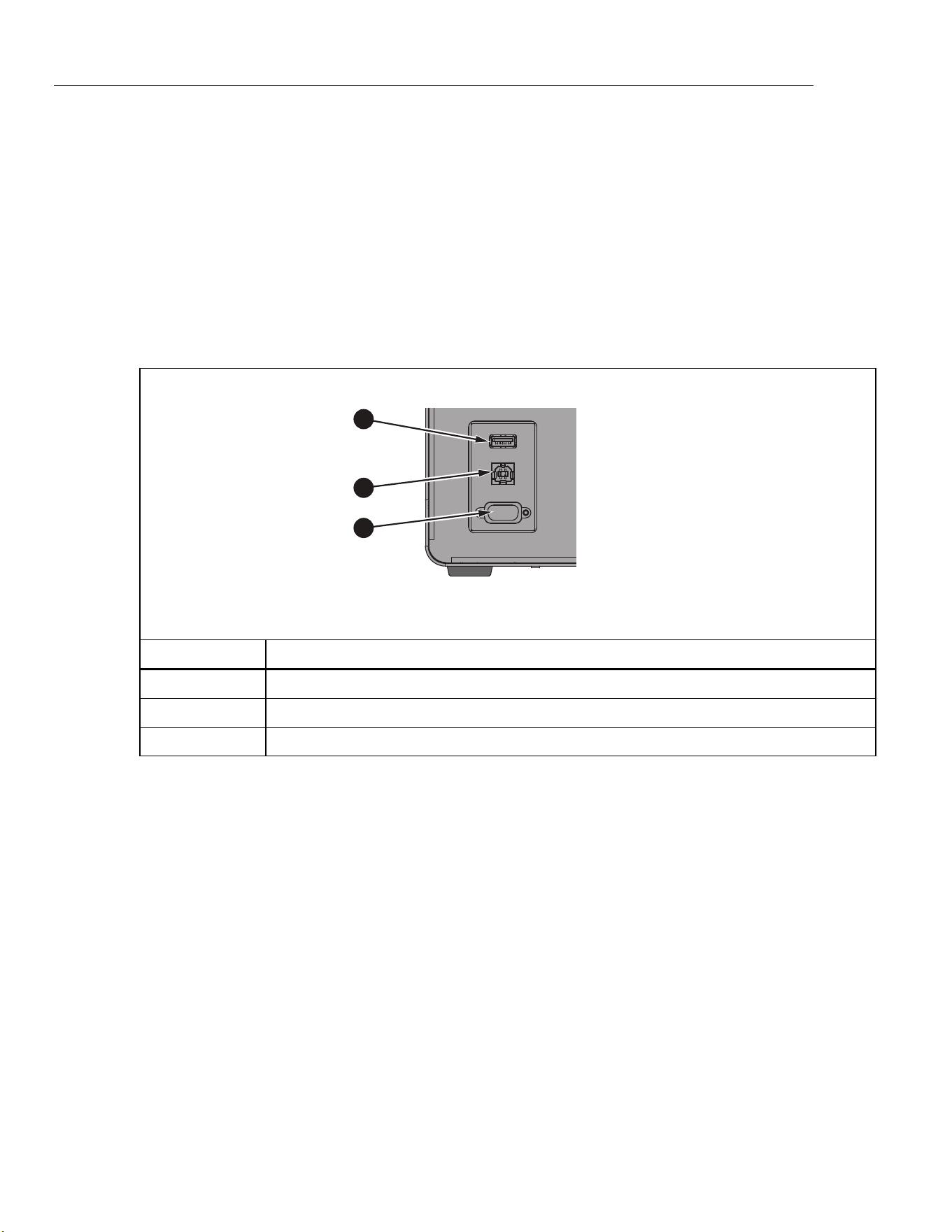
6109A/7109A
Operators Manual
42
(Setup > Probe > DUT) Default Scale
Change Span, Offset, and Unit back to the factory default values, which
are 16, 4, and “mA” respectively.
Remote Operation
A computer can control the Product with either the USB or RS-232 remote
interface.
Setup
Ports for the USB device and RS-232 interface are located in the lower-left area
of the front panel of the Product as shown in Figure 14. Some setup may be
required to get the remote interface to function properly with the computer.
1
2
3
icu04.eps
Number Description
USB Host Port
USB Device Port
RS-232 Port
Figure 14. Remote Interface Ports
USB Device
The USB remote interface requires a special driver to be installed on the
computer. The driver can be found on the Product CD.
Connect the Product to the computer with the provided USB cable. Wait a few
seconds for the Product to be recognized as a USB device. The USB interface
shows as a virtual com port on the computer.
1.888.610.7664 sales@GlobalTestSupply.com
Fluke-Direct.com

Portable Calibration Baths
Remote Operation
43
RS-232
The Product’s RS-232 port is configured as DTE (data terminal equipment). Use
a null-modem cable with two female 9-pin subminiature D connectors, such as
Fluke item number 2200962. The bus protocol is 8 data bits, 1 stop bit, no parity,
and no flow control. The baud rate is selectable from 1200 to 38400.
Response data is terminated with CR or LF or a combination depending on the
Termination setting (see Remote). The Product accepts CR or LF or both when it
receives commands.
To configure the RS-232 interface:
1. Push .
2. Push the Instrument softkey .
3. Push the Remote softkey .
4. Push or , then to change Serial Baud Rate.
5. Push the Done softkey to return to the first screen.
Test
Once the remote interface is set up, test several commonly used commands:
1. Run terminal software such as PuTTY.
2. Select the COM port associated with the Product.
3. Select the matching baud rate.
4. Type the command SYST:BEEP:IMM and push Enter on the remote
computer. The Product should beep.
5. Type the command *IDN? and push Enter on the remote computer. Product
information should appear in the terminal window.
6. Type the commands SOUR:SPO 50 (push Enter on the remote computer)
and OUTP:STAT 1 (push Enter on the remote computer). The Product should
begin to heat to 50 °. (Be sure to include a space between the command and
the parameter.)
7. Type the command SOUR:SENS:DATA? and push Enter on the remote
computer. The fluid temperature should be returned.
8. Type the command SYST:ERR? and push Enter on the remote computer.
The response should be 0, “No error”.
1.888.610.7664 sales@GlobalTestSupply.com
Fluke-Direct.com

6109A/7109A
Operators Manual
44
Commands
This sections lists the remote commands used by the Product.
SCPI Conformance Information
The Product complies with IEEE-488.2 and SCPI (Standard Commands and
Programmable Interface) version 1999.0 with regards to standard commands,
syntax, and data formats.
Many commands have two forms: the command form and query form. The
command form changes a setting or performs an action. The query form, which
ends with a question mark ‘?’, returns data from the Product.
All commands are sequential. Execution of a command is immediate and
completes before any subsequent command is executed.
Parameters or keywords shown in square brackets “[ ]” are optional. Parameters
shown separated by ‘|’ are alternative values.
Some commands, as noted, may be password protected. The password must be
given with the command SYSTem:PASSword:CENable
(<SYSTem:PASSword[:CENable]>). Some commands are conditionally
password protected depending on the security setting.
Some commands, as noted, are only available in the 7109A-P and 6109A-P.
Command Reference
Commands are listed below in alphabetical order with explanations.
*CLS
Clear status registers and the error queue.
*ESE <numeric_value>
*ESE?
Set bits in the IEEE-488.2 Event Status Enable Register.
<numeric_value> is a decimal number that ranges from 0 to 255. This
determines which bits of the Standard Event Status Register affect ESB
summary message of the Status Byte Register.
1.888.610.7664 sales@GlobalTestSupply.com
Fluke-Direct.com

Portable Calibration Baths
Commands
45
*ESR?
Return and clear the IEEE-488.2 Standard Event Status Register.
The response is a decimal number that ranges from 0 to 255. The definition of
the bits are shown in Table 5.
Table 5. *ESR Bits
Bit Name Definition
0 OPC Operation complete
1 RQC Request control (not used)
2 QYE Query error flag (not used)
3 DDE Device-specific error flag
4 EXE Execution error flag
5 CME Command error flag
6 URQ User request (not used)
7 PON Power on
*IDN?
Return product information. The response contains the manufacturer, model
number, serial number, and firmware version numbers.
*OPC
*OPC?
Operation complete. Since all commands are sequential, this command is not
necessary for synchronization.
*OPT?
Return the product configuration.
The response is 1 if the Product is equipped with the Input Module (7109A-P or
6109A-P only). It is 0 otherwise.
*RST
Reset operational settings.
• Stop temperature control
• Set the setpoint to 25 °C
• Set Control Sensor to Internal
• Set Ramp Enable to OFF
• Set Stability Beep to ON
• Set Stability Window to 0.05 °C
• Stop program execution
1.888.610.7664 sales@GlobalTestSupply.com
Fluke-Direct.com

6109A/7109A
Operators Manual
46
*SRE <numeric_value>
*SRE?
Set bits in the IEEE-488.2 Service Request Enable Register.
<numeric_value> is a decimal number that range from 0 to 255. This determines
which bits of the Status Byte Register affect the MSS bit of the Status Byte
Register.
*STB?
Return the IEEE-488.2 Status Byte Register.
The response is a decimal number that range from 0 to 255. The definitions of
the bits are shown in Table 6.
Table 6. *STB Bits
Bit Name Definitions
0 — not used
1 — not used
2 ERR Error message flag
3 QSB Questionable status flag
4 MAV Message available (not used)
5 ESB Standard Event Status flag
6 MSS Master summary status
7 OSB Operation status flag
*TST?
Return the self-test results.
The response is 1 if a failure was detected or 0 otherwise.
*WAI
Wait to continue. Since all commands are sequential, this command is not
necessary for synchronization.
CALibration:DATE <year>,<month>,<day>
CALibration:DATE?
Store the given date as the Product calibration date.
This command is password protected.
CALibration:DATE:MODule <year>,<month>,<day>
CALibration:DATE:MODule?
(-P models only) Store the given date as the calibration date of the Input Module.
This command is password protected.
1.888.610.7664 sales@GlobalTestSupply.com
Fluke-Direct.com

Portable Calibration Baths
Commands
47
CALCulate:AVERage:CLEAr
Clear the statistical average and standard deviation for fluid temperature,
reference probe, and DUT sensor readings.
CALCulate:AVERage:WINDow <numeric_value>
CALCulate:AVERage:WINDow?
Set the time window in seconds for the moving average and standard deviation.
<numeric_value> is either 10, 60, or 300.
CALCulate1:AVERage[:AVERage]?
(-P models only) Return the moving average of the reference probe readings.
The response is a temperature value in °C or °F and depends on the temperature
unit setting.
CALCulate1:AVERage:SDEViation?
(-P models only) Return the moving standard deviation of the reference probe
readings.
The response is a temperature value in °C or °F and depends on the temperature
unit setting.
CALCulate1:CONVersion:CATalog?
(-P models only) Return the list of supported PRT types for the reference probe.
The response is CVD,ITS90,IEC,RES,NONE.
CALCulate1:CONVersion:DATE <year>,<month>,<day>
CALCulate1:CONVersion:DATE?
(-P models only) Store the given date as the reference probe calibration date.
This command is password protected.
CALCulate1:CONVersion:TYPE?
(-P models only) Set the reference probe type.
<type> is either CVD, ITS-90, IEC, RES, or NONE.
This command is conditionally password protected.
CALCulate1:CONVersion:TYPE <type>
CALCulate1:CONVersion:PARameter:CATalog?
(-P models only) Return the list of characterization coefficients associated with
the selected PRT type.
1.888.610.7664 sales@GlobalTestSupply.com
Fluke-Direct.com

6109A/7109A
Operators Manual
48
CALCulate1:CONVersion:PARameter:VALue <parameter>,<n>
CALCulate1:CONVersion:PARameter:VALue? <parameter>
(-P models only) Set the value of the given reference probe characterization
coefficient.
<parameter> is the name of the characterization coefficient.
<n> is the value the characterization coefficient.
This command is conditionally password protected.
CALCulate1:CONVersion:PROGram
(-P models only) Program the reference probe memory with the current PRT
type, characterization coefficients, serial number, and calibration date.
This command is password protected.
CALCulate1:CONVersion:SNUMber <string>
CALCulate1:CONVersion:SNUMber?
(-P models only) Set the reference probe serial number.
<string> is an alphanumeric serial number or identification string that contains up
to10 characters, enclosed in quotation marks.
This command is conditionally password protected.
CALCulate1:CONVersion:STATe?
(-P models only) Return the connection state of the reference probe memory.
The response is 1 if the Product and reference probe memory are linked or 0
otherwise.
CALCulate1:CONVersion:TEST? <numeric_value>
(-P models only) Return temperature calculated from the given resistance that
uses the current reference PRT type and characterization coefficients.
<numeric_value> is the simulated PRT resistance in ohms.
The response is temperature in °C or °F and depends on the temperature unit
setting.
CALCulate1:DATA?
(-P models only) Return the reference probe temperature.
The response is temperature in °C or °F and depends on the temperature unit
setting, unless the PRT type is RES or NONE.
CALCulate2:AVERage[:AVERage]?
(-P models only) Return the moving average of the DUT sensor readings.
The response is a temperature value in °C or °F and depends on the temperature
unit setting.
1.888.610.7664 sales@GlobalTestSupply.com
Fluke-Direct.com

Portable Calibration Baths
Commands
49
CALCulate2:AVERage:SDEViation?
(-P models only) Return the moving standard deviation of the DUT sensor
readings.
The response is a temperature value in °C or °F and depends on the temperature
unit setting.
CALCulate2:CONVersion:CATalog? [<function>]
(-P models only) Return the list of supported RTD types or thermocouple types.
<function> is either RTD or TC. If the parameter is omitted, the current function is
assumed.
For RTD, the response is PT_A385,PT_A392,PT_JIS,NI_120,RES.
For TC, the response is C,D,E,G,J,K,L,M,N,R,S,T,U,W,MV.
CALCulate2:CONVersion:TYPE <type>
CALCulate2:CONVersion:TYPE?
(-P models only) Set the DUT sensor type.
<type> is the specific DUT sensor type. The allowed types depend on the current
function (see CALCulate2:CONVersion:CATalog? and SENSE2:FUNCtion).
When the DUT sensor type is changed, the RTD wires setting (see
INPut2:RTD:WIRes) and transmitter loop power setting (see
INPut2:MAMP:LPOWer) revert to their default values.
This command is conditionally password protected.
CALCulate2:DATA?
(-P models only) Return the DUT sensor reading.
If the DUT sensor is configured to produce temperature readings, the response is
in °C or °F and depends on the temperature unit setting.
CALCulate2:SCALe:SPAN <numeric_value>|DEF
CALCulate2:SCALe:SPAN?
(-P models only) Set the mA scaling span.
<n> is the span between the reading at 20 mA and the reading at 4 mA. The
default is 16.
This command is conditionally password protected.
1.888.610.7664 sales@GlobalTestSupply.com
Fluke-Direct.com

6109A/7109A
Operators Manual
50
CALCulate2:SCALe:OFFSet <numeric_value>|DEF
CALCulate2:SCALe:OFFSet?
(-P models only) Set the mA scaling offset.
<n> is the reading at 4 mA. The default is 4.
This command is conditionally password protected.
CALCulate2:SCALe:UNIT <string>|DEF
CALCulate2:SCALe:UNIT?
(-P models only) Set the mA scaling unit of measurement.
<string> is an alphanumeric string containing up to 4 characters, enclosed in
quotation marks. Allowed characters are ‘A’ to ‘Z’, ‘a’ to ‘z’, ‘0’ to ‘9’, ‘/’, ‘-‘, ‘%’,
and ‘@’. The character ‘@’ is displayed as the degree symbol ° on the display.
The default setting is “mA”.
This command is conditionally password protected.
DATA:RECord[:STATe] <boolean>
DATA:RECord[:STATe]?
Turns data recording on or off.
A properly formatted memory device must be already connected to the USB host
port.
<boolean> is 1(ON) or 0 (OFF).
DATA:RECord:FILename <filename>
DATA:RECord:FILename?
Specify the name of the file to which data is recorded.
<filename> is the name of the file that can have up to 14 characters. The
extension “.txt.” is automatically appended to the filename when the file is
created.
DISPlay:BRIGhtness <numeric_value>
DISPlay:BRIGhtness?
Set the brightness of the front panel LCD.
<numeric_value> is the fractional brightness from 0 to 1. The actual brightness is
rounded to 0.4 (low), 0.7 (medium), or 1.0 (high).
1.888.610.7664 sales@GlobalTestSupply.com
Fluke-Direct.com

Portable Calibration Baths
Commands
51
DISPlay:DATE:FORMat <format>
DISPlay:DATE:FORMat?
Set the format for dates on the display.
<format> is either “YYYY-MM-DD”, “YYYY/MM/DD”, “DD/MM/YYYY”,
“DD.MM.YYYY”, or “MM-DD-YYYY”.
DISPlay:DECimal:FORMat <boolean>
DISPlay:DECimal:FORMat?
Select the decimal point for numbers on the display.
<boolean> is either 0 for period ‘.’ or 1 for comma ‘,’.
DISPlay:LANGuage <language>
DISPlay:LANGuage?
Select the language for the display.
<language> is either “ENGLISH”, “FRENCH”, “SPANISH”, “PORTUGUESE”,
“GERMAN”, “RUSSIAN”, “CHINESE”, “JAPANESE”, or “KOREAN”.
DISPlay:SAVer <numeric_value>
DISPlay:SAVer?
Set the screen saver timeout period.
<numeric_value> is the time in minutes. 0 disables screen saver. A non-zero
value is rounded to 10, 30, or 60.
DISPlay:TEMPerature:DIGits <numeric_value>
DISPlay:TEMPerature:DIGits?
Set the number of decimal places for temperature values on the display.
<numeric_value> is the number of decimals places, either 2 or 3.
DISPlay:TIME:FORMat 12|24
DISPlay:TIME:FORMat?
Set the format for time on the display.
FETCh?
(-P models only) Return the reference probe temperature and DUT sensor
reading.
The response is temperature in °C or °F and depends on the temperature unit
setting.
1.888.610.7664 sales@GlobalTestSupply.com
Fluke-Direct.com

6109A/7109A
Operators Manual
52
INITiate
(-P models only) Measurement is continuous and automatic, so no triggering is
necessary.
INITiate:CONTinuous 1
INITiate:CONTinuous?
(-P models only) Measurement is always continuous.
INPut2:MAMP:LPOWer <boolean>|DEFault
INPut2:MAMP:LPOWer?
(-P models only) Turn transmitter loop power on or off.
<boolean> is 0 (OFF, default) or 1(ON).
This command is conditionally password protected.
INPut2:RTD:WIRes 2|3|4|DEFault
INPut2:RTD:WIRes?
(-P models only) Select the number of lead wires for the DUT RTD circuit. The
default is 4 wires.
This command is conditionally password protected.
MEASure?
(-P models only) Return the reference probe temperature and DUT sensor
reading.
The response is temperature in °C or °F and depends on the temperature unit
setting.
OUTPut:DATA?
Return percent heating output of the temperature control function.
The response is a decimal number of percent. The value is negative as the
Product cools. The value is 0 if control is off.
OUTPut:STATe <boolean>|DEFault
OUTPut:STATe?
Turn temperature control on or off.
<boolean> is 0 (OFF, default) or 1(ON).
*RST sets this to off.
Example:
OUTP:STATE 1
1.888.610.7664 sales@GlobalTestSupply.com
Fluke-Direct.com

Portable Calibration Baths
Commands
53
PROGram:BEEP <boolean>|DEFault
PROGram:BEEP?
Turn program beep on or off.
<boolean> is 0 (OFF) or 1(ON, default).
This command is conditionally password protected.
PROGram:CATalog?
Return a list of defined programs.
The response is a series of comma-separated program names, each enclosed in
quotation marks.
PROGram:DELete:ALL
Delete all defined programs.
Because at least one program must be defined, a new default program will be
created to replace those that have been deleted.
This command is password protected.
PROGram:EXPlicit:DEFine <name>[,<numeric_value>[,...]]
PROGram:EXPlicit:DEFine?
Create a new temperature program.
<name> is the name of the new program enclosed in quotation marks. It can
contain up to 14 characters. Characters can range from ‘A’ to ‘Z’, ‘a’ to ‘z’, ‘0’ to
‘9’, ‘-‘, ‘.’, ‘/’, and ‘_’. The name must be different from any other defined program.
<numeric_value> are values of program variables. If parameters are omitted,
default values are assumed. Variable are defined the order shown in Table 7.
1.888.610.7664 sales@GlobalTestSupply.com
Fluke-Direct.com

6109A/7109A
Operators Manual
54
Table 7. Program Variables
Setting Name Description
Cycles CYCL Number of cycles. Range is 1 to 99. Default is 1.
Order ORD Setpoint order. Range is 0 (linear, default) or 1 (up/down).
Dwell Time DWEL Dwell time in minutes. Range is 1 to 900. Default is 10.
Ramp Rate RRAT Heating or cooling rate in °C per minute or °F per minute.
Ramp Enable RREN Turn ramp rate on or off. Range is 0 (off, default) or 1(on).
Points POIN Number of setpoints, 1 to 8. Default is 2.
Setpoint 1 SPO1 Setpoint temperature in °C or °F. Default is 40 °C or 104 °F.
Setpoint 2 SPO2 Setpoint temperature in °C or °F. Default is 40 °C or 104 °F.
Setpoint 3 SPO3 Setpoint temperature in °C or °F. Default is 40 °C or 104 °F.
Setpoint 4 SPO4 Setpoint temperature in °C or °F. Default is 40 °C or 104 °F.
Setpoint 5 SPO5 Setpoint temperature in °C or °F. Default is 40 °C or 104 °F.
Setpoint 6 SPO6 Setpoint temperature in °C or °F. Default is 40 °C or 104 °F.
Setpoint 7 SPO7 Setpoint temperature in °C or °F. Default is 40 °C or 104 °F.
Setpoint 8 SPO8 Setpoint temperature in °C or °F. Default is 40 °C or 104 °F.
Example:
PROG:DEF “My_Program”,2,0,5,1,0,3,0.0,50.0,100.0
This command is conditionally password protected.
The query returns the values of the parameters of the selected program in a
comma separated list.
PROGram:EXPlicit:DELete <name>
Delete the specified program.
<name> is the name of an existing program enclosed in quotation marks.
Since at least one program must be defined, a new default program will be
created if necessary.
This command is conditionally password protected.
PROGram:EXPlicit:EXEcute <name>
Run the specified program.
<name> is the name of an existing program enclosed in quotation marks.
No program may be running, otherwise the command will fail.
1.888.610.7664 sales@GlobalTestSupply.com
Fluke-Direct.com

Portable Calibration Baths
Commands
55
PROGram[:SELected]:DEFine <name>[,<numeric_value>[,...]]
PROGram[:SELected]:DEFine?
Create a new temperature program and select the new program for further
operations. This command has the same function as PROGram:EXPlicit:DEFine.
PROGram[:SELected]:NAME <name>
PROGram[:SELected]:NAME?
Select a program for further operations.
<name> is the name of an existing program enclosed in quotation marks.
PROGram[:SELected]:NUMBer <variable>,<numeric_value>|DEFault
PROGram[:SELected]:NUMBer? <variable>
Set a program variable in the selected program.
<variable> is the name of a variable (see Table 5).
<numeric_value> is the value of the variable.
PROGram[:SELected]:STATe <boolean>|RUN|PAUSe|CONTinue|STOP
PROGram[:SELected]:STATe?
Change the execution state of the selected program.
<boolean> is 0 (STOP) or 1(RUN). Which parameters are allowed depends on
the present state.
*RST stops program execution.
The query returns the present state, either STOPPED, RUNNING, or PAUSED.
PROGram:MEMory:CLEar:ALL
(-P models only) Clear memory of all test reports.
This command is password protected.
PROGram:REPort:COUNt?
(-P models only) Return the number of test reports stored in memory.
PROGram:REPort:ENABle <boolean>|DEFault
PROGram:REPort:ENABle?
(-P models only) Turn Program Report on or off.
<boolean> is 0 (OFF) or 1(ON, default).
This command is conditionally password protected.
1.888.610.7664 sales@GlobalTestSupply.com
Fluke-Direct.com

6109A/7109A
Operators Manual
56
PROGram:REPort:REFerence <boolean>|DEFault
PROGram:REPort:REFerence?
(-P models only) Select the reference source for program reports.
<boolean> is 0 (internal control sensor) or 1(external reference probe, default).
This command is conditionally password protected.
PROGram:REPort:TOLerance <numeric_value>|DEFault
PROGram:REPort:TOLerance?
(-P models only) Set the pass tolerance for program reports.
<numeric_value> is the tolerance number. Range is 0.001 to 50. Default is 1.
READ?
(-P models only) Return the reference probe temperature and DUT sensor
reading.
The response is temperature in °C or °F and depends on the temperature unit
setting.
SENSe1:CALibration:PARameter<index> <numeric_value>
SENSe1:CALibration:PARameter<index>?
(-P models only) Set a calibration parameter for the Input Module PRT/RTD
inputs.
<index> selects the calibration parameter; 1: REF1C0; 2: REF1C100.
<numeric_value> is the value to which the calibration parameter is set.
Calibration parameters should only be changed by a qualified technician as part
of a calibration procedure.
This command is password protected.
SENSe1:DATA?
(-P models only) Return the reference probe resistance in ohms.
SENSe2:CALibration:PARameter<index> <numeric_value>
SENSe2:CALibration:PARameter<index>?
(-P models only) Set a calibration parameter for the Input Module thermocouple
and transmitter inputs.
<index> specifies the calibration parameter; 1: TCC0; 2: TCC100; 3: TCCRJ; 4:
mAC4; 6: mAC22.
<numeric_value> is the value to which the calibration parameter is set.
Calibration parameters should only be changed by a qualified technician as part
of a calibration procedure.
This command is password protected.
1.888.610.7664 sales@GlobalTestSupply.com
Fluke-Direct.com

Portable Calibration Baths
Commands
57
SENSe2:DATA?
(-P models only) Return the DUT input measurement as resistance in ohms,
voltage in mV, or current in mA.
SENSe2:FUNction <function>
SENSe2:FUNction?
(-P models only) Select the function for the Input Module DUT inputs.
<function> is either RTD, TC, MA, or NONE.
This command is conditionally password protected.
SOURce:CUTout:CLEAr
Clear cutout condition.
For the cutout to be cleared, the fluid temperature must be less than the cutout
temperature setting.
SOURce:CUTout:EVENt?
Return the most recent cutout event.
The response is a sum of one or more codes. Codes are interpreted as in
Table 8:
Table 8. Cutout Codes
Code Definitions
0 No cutout occurred
1 Fluid temperature exceeded the cutout temperature
2 Tank is empty
16 Heater temperature exceeded the cutout temperature
32 Stir motor failed
SOURce:CUTout:LEVel <numeric_value>
SOURce:CUTout:LEVel?
Set the cutout temperature.
<numeric_value> is the temperature in °C or °F and depends on the temperature
unit setting.
This command is conditionally password protected.
SOURce:CUTout:STATe?
Return the cutout condition.
The response is 1 if the cutout is active, or 0 otherwise.
1.888.610.7664 sales@GlobalTestSupply.com
Fluke-Direct.com

6109A/7109A
Operators Manual
58
SOURce:LCONstants:DERivative <numeric_value>
SOURce:LCONstants:DERivative?
Set the derivative loop constant for temperature control.
Control parameters affect the temperature stability of the Product and should
only be changed by a qualified personnel.
This command is password protected.
SOURce:LCONstants:INTegral <numeric_value>
SOURce:LCONstants:INTegral?
Set the integral loop constant for temperature control.
Control parameters affect the temperature stability of the Product and should
only be changed by a qualified personnel.
This command is password protected.
SOURce:LCONstants:PBANd <numeric_value>
SOURce:LCONstants:PBANd?
Set the proportional band loop constant for temperature control.
Control parameters affect the temperature stability of the Product and should
only be changed by a qualified personnel.
This command is password protected.
SOURce:RAMP:RATE <numeric_value>
SOURce:RAMP:RATE?
Set Ramp Rate.
<numeric_value> is the ramp rate value in °C per minute or °F per minute.
The ramp function must be enabled for Ramp Rate to apply.
SOURce:RAMP:ENABle <boolean>
SOURce:RAMP:ENABle?
Set Ramp Enable.
<boolean> is 1(ON) or 0 (OFF).
When Ramp Enable is ON, the heating or cooling rate is reduced according to
the Ramp Rate setting. When Ramp Enable is OFF, the Product will heat or cool
as fast as possible to a new setpoint.
1.888.610.7664 sales@GlobalTestSupply.com
Fluke-Direct.com

Portable Calibration Baths
Commands
59
SOURce:SENSe:CALibration:PARameter<index> <numeric_value>
SOURce:SENSe:CALibration:PARameter<index>?
Set a calibration parameter for the control sensor.
<index> specifies the calibration parameter; 1: TEMP1; 2: TEMP2; 3: TEMP3.
<numeric_value> is the value to which the calibration parameter is set.
Calibration parameters should only be changed by a qualified technician as part
of a calibration procedure.
This command is password protected.
SOURce:SENSe:AVERage:[:AVERage]?
Return the moving average of the fluid temperature.
The response is a temperature value in °C or °F and depends on the temperature
unit setting.
SOURce:SENSe:AVERage:SDEViation?
Return the moving standard deviation of the fluid temperature.
The response is a temperature value in °C or °F and depends on the temperature
unit setting.
SOURce:SENSe:DATA?
Return the fluid temperature.
The response is a temperature value in °C or °F and depends on the temperature
unit setting.
SOURce:SENSe:ROUTe <boolean>|DEFault
SOURce:SENSe:ROUTe?
Select the control sensor source.
<boolean> is 0 (Internal sensor) or 1 (reference probe).
This command is conditionally password protected.
1.888.610.7664 sales@GlobalTestSupply.com
Fluke-Direct.com

6109A/7109A
Operators Manual
60
SOURce:SPOint <numeric_value>
SOURce:SPOint? [MINimum|MAXimum]
Set the temperature setpoint.
<numeric_value> is temperature in °C or °F and depends on the temperature unit
setting. The range depends on the model.
Example:
SOUR:SPO 50.02
Temperature control must be turned on for the setpoint to take effect (see the
command OUTPut:STATe).
SOURce:SPOint:DEFine<index> <numeric_value>
SOURce:SPOint:DEFine<index>? [MINimum|MAXimum]
Set a preset setpoint.
<index> is the preset number. Range is 1 to 8.
<numeric_value> is temperature in °C or °F and depends on the temperature unit
setting. The range depends on the model.
Example:
SOUR:SPO:DEF8 100
SOURce:SPOint:SELect <index>
Set the temperature setpoint to a selected preset.
Temperature control must be turned on for the setpoint to take effect (see the
command OUTPut:STATe).
SOURce:STABility:BEEP <boolean>
SOURce:STABility:BEEP?
Enable the ready beep.
<boolean> is 0 (OFF) or 1 (ON).
SOURce:STABility:CONDition?
Return the ready condition.
The response is 0 (settling or off) or 1 (stable, ready).
SOURce:STABility:LIMit <numeric_value>|DEFault
SOURce:STABility:LIMit?
Set the stability window
<numeric_value> is temperature in °C or °F and depends on the temperature unit
setting. The range depends on the model.
This command is conditionally password protected.
1.888.610.7664 sales@GlobalTestSupply.com
Fluke-Direct.com

Portable Calibration Baths
Commands
61
SOURce:STIR:CALibration <numeric_value>
SOURce:STIR:CALibration?
Set the reference stir power percent.
<numeric_value> is the stir power percent.
Calibration parameters should only be changed by a qualified technician as part
of a calibration procedure.
This command is password protected.
SOURce:STIR:POWer?
Return the stir power percent.
SOURce:STIR:SPEEd <numeric_value>
SOURce:STIR:SPEEd?
Set the stir speed.
<numeric_value> is the stir speed in revolutions per minute (RPM).
Calibration parameters should only be changed by a qualified technician as part
of a calibration procedure.
This command is password protected.
SOURce:STIR:TACHometer?
Return the actual stir speed.
The response is the stir speed in revolutions per minute (RPM). Stir speed is 0 if
control is off.
STATus:OPERation[:EVENt]?
Return and clear the SCPI Operation Status Event register.
(-P models only) The response is 16 (measurement ready) if the latest reading of
the reference probe has not yet been queried (see the command FETCh?).
STATus:OPERation:CONDition?
Return the SCPI Operation Status Condition register.
(-P models only) The response is 16 (Measuring).
STATus:OPERation:ENABle <numeric_value>
STATus:OPERation:ENABle?
Set bits in the SCPI Operation Status Mask register.
<numeric_value> is a decimal number that ranges from 0 to 255. This
determines which bits of the Operation Status Event Register affect the OSB
summary message of the Status Byte Register.
1.888.610.7664 sales@GlobalTestSupply.com
Fluke-Direct.com

6109A/7109A
Operators Manual
62
STATus:PRESet
Set the Operation Status Mask register to 0 and the Questionable Status Mask
register to 0.
STATus:QUEStionable:CONDition?
Return the SCPI Questionable Status Condition register.
(-P models only) The response is 16 if the latest reading of the reference probe
or DUT sensor is out of range.
STATus:QUEStionable[:EVENt]?
Return and clear the SCPI Questionable Status Event register.
(-P models only) The response is 16 if a reading of the reference probe or DUT
sensor was out of range.
STATus:QUEStionable:ENABle <numeric_value>
STATus:QUEStionable:ENABle?
Set bits in the SCPI Questionable Status Mask register.
<numeric_value> is a decimal number ranging from 0 to 255. This determines
which bits of the Questionable Status Event Register affect the QSB summary
message of the Status Byte Register.
SYSTem:BEEP:IMMediate
Make the Product beep.
SYSTem:BEEP:KEY <boolean>
SYSTem:BEEP:KEY?
Enable key beep.
<boolean> is 0 (OFF) or 1 (ON).
SYSTem:COMMunicate:SERial:BAUD <numeric_value>
SYSTem:COMMunicate:SERial:BAUD?
Set the baud rate of the RS-232 port.
<numeric_value> is either 1200, 2400, 4800, 9600, 19200, or 38400.
SYSTem:COMMunicate:SERial:FEED <boolean>
SYSTem:COMMunicate:SERial:FEED?
Turn on serial port monitor.
<boolean> is 0 (OFF) or 1 (ON). When this function is on, the fluid temperature is
transmitted to the serial port automatically at a rate of one reading per second.
The temperature is in °C or °F. The default is OFF.
1.888.610.7664 sales@GlobalTestSupply.com
Fluke-Direct.com

Portable Calibration Baths
Commands
63
SYSTem:COMMunicate:SERial:LINefeed <boolean>
SYSTem:COMMunicate:SERial:LINefeed?
Enable LF termination character.
<boolean> is 0 (OFF) or 1 (ON). When this setting is on, CR and LF are both
transmitted at the end of every response. If the setting is OFF, only CR is
transmitted. The default is OFF.
SYSTem:DATE <year>,<month>,<day>
SYSTem:DATE?
Set the clock date.
This command is conditionally password protected.
SYSTem:ERRor[:NEXT]?
Return and clear the latest error from the error queue.
The response is an error code and message, separated by a comma.
Example:
-100,”Command error”
If the error queue is empty, the message is “No error”.
Example:
0,”No error”
SYSTem:KLOCk <boolean>
SYSTem:KLOCk?
Disable the front panel keys.
<boolean> is 0 (OFF, unlocked) or 1 (ON, locked). After power-on, the setting is
always 0.
SYSTem:PASSword:CDISable
Lock protected commands.
At power-on, all protected commands are locked.
SYSTem:PASSword[:CENable] <password>
Unlock protected commands.
<password> is the user password. The default password is 1234.
SYSTem:PASSword:CENable:STATe
Return the protection state.
The response is 0 (locked) or 1 (unlocked).
1.888.610.7664 sales@GlobalTestSupply.com
Fluke-Direct.com

6109A/7109A
Operators Manual
64
SYSTem:PASSword:NEW <password>
Set the password.
<password> is a four-digit number.
This command is password protected.
SYSTem:PASSword:PROTection <boolean>
SYSTem:PASSword:PROTection?
Set the password protection level.
<boolean> is 0 (OFF) or 1 (ON). When this setting is on, conditionally password
protected commands are protected. When the setting is off, only calibration
commands and password commands are protected.
This command is password protected.
SYSTem:TIME <hour>,<minute>,<second>
SYSTem:TIME?
Set the clock time.
This command is conditionally password protected.
SYSTem:VERSion
Return the SCPI version.
The response is “1999.0”.
UNIT:TEMPerature <unit>
UNIT:TEMPerature?
Select the temperature unit.
<unit> is C or CEL for degrees Celsius or F or FAR for degrees Fahrenheit.
Fahrenheit may not be available in some regions of the world.
1.888.610.7664 sales@GlobalTestSupply.com
Fluke-Direct.com

Portable Calibration Baths
Maintenance
65
Maintenance
This section explains routine operator maintenance necessary to keep the
Product in optimal condition.
Clean the Product
The tank and other metal parts are made of stainless steel to resist corrosion.
Keep the outside of the Product dry to prevent fluid seeping inside or spreading
to other equipment. Use paper towels or other absorbent material to wipe the
fluid off all surfaces. Complete removal of fluid residue may require a special mild
solvent. Steris SPOR-KLENZ and Dow Corning OS-2 are effective for silicone.
Use solvents only in a well-ventilated area. Refer to the material safety data
sheet (SDS) of the cleaner for additional safety precautions. Dispose of used
cleaning materials properly. See Drain the Bath Fluid.
The stir motor cover can be temporarily removed so that the area underneath it
can be cleaned. Use a T20 Torx driver to remove the carrying handle and a T10
Torx driver for the stir motor cover. Replace the stir motor cover before you
operate the Product.
Clean Up Spills
Fluid spilled on the floor is a safety hazard. To avoid accidents, follow these
precautions and instructions.
Caution
• Be careful when you fill and operate the Product to avoid
drips and spills.
• Keep cleanup materials on hand.
• If a spill occurs, close the area to traffic until the spill is
cleaned up.
• Use paper towels or other absorbent material to wipe up
spilled fluid.
• Use a ventilation system to collect vapor emitted by the
fluid or cleaning solutions.
• Dispose of used cleanup materials properly.
Fluids and solvents may require additional safety precautions. Refer to the
material’s safety data sheet (SDS).
Bath fluid residue can be removed with a suitable mild solvent such as Steris
SPOR-KLENZ or Dow Corning OS-2 for silicone.
1.888.610.7664 sales@GlobalTestSupply.com
Fluke-Direct.com

6109A/7109A
Operators Manual
66
Check the Bath Fluid
Optimal temperature performance requires bath fluid in good condition. Check
the fluid often to ensure it stirs easily. Replace the fluid before it begins to
polymerize. The fluid’s viscosity should be 50 centistokes or less at the minimum
temperature. The viscosity of a silicone fluid will increase over time, and it can
thicken quickly at the end of the bath fluid’s lifespan.
Measure viscosity with a viscosity cup. For safety and accuracy, the fluid
temperature should be ≤35 °C.
An alternative method to detect a change in viscosity is the Stir Power indicator
in the Diagnostics screen (see Diagnostics). Higher viscosity causes greater load
on the stir motor. A significant change of viscosity can be seen as an increase in
Stir Power >1 %. Check the Stir Power while the fluid is ≤35 °C.
Since the 7109A can operate at temperatures colder than the environment’s dew
point, it is susceptible to water condensing into the fluid. Avoid extended
operation at temperatures below the environment, especially with the tank open.
To remove condensed water, set the setpoint to 100 °C and hold that
temperature for an hour to let the water evaporate.
Drain the Bath Fluid
Occasionally it is necessary to drain the tank to replace the bath fluid or transport
the Product. A clean, wide-mouth container large enough to contain at least
2.5 liters of fluid is necessary.
Warning
To prevent personal injury, wear appropriate personal
protective equipment.
To drain the bath fluid:
1. Set the setpoint to 25 °C and wait for the Product to heat or cool to between
5 °C and 60 °C.
2. Switch off the Product and disconnect the mains power cord.
3. Remove the overflow container and pour its contents into the large container.
4. Remove all accessories.
5. Remove the drain cover.
6. Move the Product to the edge of the table so that the drain tube extends over
the edge.
7. Position the container on a platform under the drain tube so that the fluid falls
into the mouth of the container. Be aware that pressure will cause the fluid to
flow outward.
8. Unscrew and remove the drain plug. As the bath fluid flows out into the
container, watch carefully to ensure the container stays properly positioned to
catch all the fluid.
9. After the fluid stops, lift the front of the Product to funnel any fluid that
remains into the drain tube.
1.888.610.7664 sales@GlobalTestSupply.com
Fluke-Direct.com

Portable Calibration Baths
Calibrate the Product
67
10. Once the tank is empty, insert the drain plug and tighten it securely.
11. Replace the drain cover.
12. Use a paper towel or other clean absorbent material to remove any fluid that
remains in the tank.
13. Clean up any drips or spills.
14. Dispose of the bath fluid in a legal and environmentally-friendly manner.
Check the bath fluid disposal information.
Transport the Calibration Bath
To prepare the Product for transport:
1. Set the setpoint to 25 °C and wait for the Product to heat or cool to between
5 °C and 60 °C.
2. Turn off the Product and disconnect the mains power cord.
3. Remove all accessories.
4. Drain the fluid as explained in Drain the Bath Fluid.
5. Place the transport cover over the tank and fasten it securely.
6. Install the overflow plug on the overflow tube.
7. Wipe off any fluid on the Product.
8. Use the carrying handle and the recessed handle on the side to lift the
Product.
9. If you transport the Product by car or truck, carefully pack the Product in the
original shipping carton.
10. Follow the instructions provided in Setup to prepare the Product for operation
at the new location. Remember to remove the overflow plug when the
overflow kit is used.
Calibrate the Product
This section provides instructions to calibrate and adjust the Product to ensure it
meets performance specifications. During Calibration:
• The environment temperature should be steady between 19 °C and 27 °C.
• Avoid air drafts.
• Use the recommended silicone fluid.
• Check that the tank is filled between the MIN and MAX levels.
• Use the provided probe access cover.
1.888.610.7664 sales@GlobalTestSupply.com
Fluke-Direct.com

6109A/7109A
Operators Manual
68
Temperature Setpoint Calibration
The Product is calibrated to ensure it performs within the Temperature Source
specifications. If necessary, adjustments are made to return the Product to
specification or to optimize performance.
Table 9 lists the equipment required to calibrate the temperature setpoint
accuracy. The combined expanded (k =2) uncertainty of the calibration
equipment must be no more than 0.025 °C.
Table 9. Equipment for Temperature Setpoint Calibration
Equipment Specifications Suggested Model
Reference PRT 0.008 °C at 0 °C Fluke Calibration 5628
PRT readout 20 ppm Fluke Calibration 1560/2560
Table 10 lists the calibration points for each model. Calibration points marked
with an asterisk are also alignment points.
Table 10. Calibration Points for Temperature Setpoint Calibration
Point number 7109A Temperature 6109A Temperature
Calibration
Parameter
1 * -25 °C 35 °C TEMP1
2 0 °C 100 °C (none)
3 * 50 °C 150 °C TEMP2
4 100 °C 200 °C (none)
5 * 140 °C 250 °C TEMP3
To calibrate the temperature setpoint:
1. Place the reference PRT in the center of the tank with the tip 13 mm above
the bottom.
2. Set the Stability Window to 0.05 °C, see Operation.
3. For each calibration point:
a. Set the setpoint to the calibration point.
b. Wait for the control indicator to show stable.
c. Wait at least 30 minutes for complete settling.
d. Measure the average temperature of the reference PRT with at least 20
samples over 15 minutes.
e. Calculate the temperature setpoint error as the difference between the
average temperature and the calibration point.
f. Check that the error is no greater than the Temperature Source Accuracy
specification.
1.888.610.7664 sales@GlobalTestSupply.com
Fluke-Direct.com

Portable Calibration Baths
Calibrate the Product
69
Alignment is required if the magnitude of any error is greater than 50 % of the
specification. Adjustments are made to the calibration parameters listed in
Table 9. These are accessible in the Bath Calibration menu after the password is
entered.
For each adjustment point:
1. Get the current value of the calibration parameter associated with the
alignment point.
2. Add the error (with sign), which was obtained during the setpoint calibration
at the calibration point, to the calibration parameter.
3. Set the calibration parameter to the new value.
As an example, say the 7109A is set to 50.00 °C but the reference probe measures
49.944 °C. For this example, the calibration parameter TEMP2 is -0.103. If you
change the parameter to -0.159, this shifts the temperature so the reference probe
measures close to 50.00 °C.
After you make adjustments to the calibration parameters, repeat the setpoint
calibration to make sure that the errors at each calibration point are no
greater than 50 % of the specification.
Temperature Stability Calibration
The Product is tested to ensure it performs within the Temperature Stability
specifications. Test temperature stability at least at the two extreme calibration
points listed in Table 12. The temperature stability calibration can be performed
concurrently with the temperature setpoint calibration.
Follow these steps:
1. Insert the reference PRT into the center of the tank with the tip 13 mm above
the bottom of the tank.
2. For each calibration point:
a. Set the setpoint to the calibration point.
b. Wait for the control indicator to show stable.
c. Wait at least 30 minutes for complete settling.
d. Measure the standard deviation of the reference PRT temperature with at
least 20 samples over 15 minutes.
e. Multiply the standard deviation by 2 to get the stability measurement.
f. Check that the result is no greater than the Temperature Stability
specification.
1.888.610.7664 sales@GlobalTestSupply.com
Fluke-Direct.com

6109A/7109A
Operators Manual
70
Temperature Uniformity Calibration
Temperature uniformity calibration measures the temperature difference between
a test location and a reference location. Perform this procedure for each location
within the fluid where devices will be placed for measurement. Also perform the
procedure at each setpoint at which devices will be measured.
The temperature uniformity calibration requires two reference PRTs of the type
and specifications stated in Table 12. The test also requires a modified probe
access cover that has holes at the locations of interest.
To calibrate the temperature uniformity:
1. Insert the first reference PRT into the tank at the reference location, placing
the tip of the PRT 15 mm above the bottom of the tank.
2. Insert the second reference PRT into the tank at the test location.
3. Set the setpoint to the required temperature.
4. Wait for the control indicator to show stable.
5. Wait at least another 15 minutes for complete settling.
6. Measure the average temperature of both PRTs with at least 20 samples
over 5 minutes.
7. Calculate the temperature uniformity error as the difference between the
average temperatures of the two PRTs.
1.888.610.7664 sales@GlobalTestSupply.com
Fluke-Direct.com

Portable Calibration Baths
Calibrate the Product
71
Input Module Calibration
This section provides instructions to calibrate and adjust the Input Module in the
7109A-P and 6109A-P. Table 11 lists the required equipment.
Table 11. Equipment for Input Module Calibration
Equipment Specifications Suggested Model
0 Ω 4-wire short 0.0005 Ω —
25 Ω 4-wire resistor 0.0005 Ω Fluke 742A-25
100 Ω 4-wire resistor 0.001 Ω Fluke 742A-100
200 Ω 4-wire resistor 0.002 Ω —
400 Ω 4-wire resistor 0.004 Ω —
Multifunction calibrator
mV: 2.0 µV
mA: 40 ppm + 0.4 µA
Fluke Calibration 5730A
Type E thermocouple 0.06 °C at 25 °C or 35 °C —
Calibration bath 0.1 °C at 25 °C or 35 °C
Fluke Calibration 7109A or
6109A
Reference PRT 0.008 °C Fluke Calibration 5628
PRT readout 20 ppm Fluke Calibration 1560/2560
Suitable test leads, connectors, and adapter cables are also necessary.
1.888.610.7664 sales@GlobalTestSupply.com
Fluke-Direct.com

6109A/7109A
Operators Manual
72
Table 12 lists calibration points. Those marked with an asterisk are also
alignment points.
Table 12. Calibration Points for Input Module Calibration
Number Terminals Configuration Quantity
Calibration
Parameter
1 *
Reference
Reference:
Resistance
0 Ω REF1C0
2 25 Ω (none)
3 * 100 Ω REF1C100
4 200 Ω (none)
5 400 Ω (none)
6 DUT 4-wire
DUT: RTD, 4
wires,
resistance
100 Ω (none)
7 DUT 3-wire
DUT: RTD, 3
wires,
resistance
100 Ω (none)
8
Thermocouple
DUT:
Thermocouple,
mV
-10 mV (none)
9 * 0 mV TCC0
10 50 mV (none)
11 * 100 mV TCC100
12 *
DUT:
Thermocouple,
E
25 °C or 35 °C TCCRJ
13
4–20 mA
DUT: mA, Loop
Power OFF,
default scaling
0 mA (none)
14 * 4 mA mAC4
15 12 mA (none)
16 20 mA (none)
17 * 22 mA mAC22
1.888.610.7664 sales@GlobalTestSupply.com
Fluke-Direct.com

Portable Calibration Baths
Calibrate the Product
73
The source for the 25 °C/35 °C thermocouple calibration point is the E
thermocouple immersed in the Product beside the reference PRT. Set the bath to
25 °C (7109A) or 35 °C (6109A). Get the reference temperature from the
reference PRT and readout.
To calibrate Input Module:
1. Set the statistics Time Window to 60 s.
2. For each calibration point:
a. In the Setup > Probe menu, select the PRT or DUT Type, see Table 12.
b. Connect the electrical standard to the terminals, see Table 12.
c. Set the source to output the quantity shown in Table 12.
d. Wait at least 2 minutes for the readings to settle.
e. Get the average reading in the Monitor > Statistics.
f. Calculate the error as the difference between the average reading and
the source quantity.
g. Check that the error is no greater than the specification.
Adjustment is required if the magnitude of any error is >50 % of the specification.
Adjustments are made to the calibration parameters listed in Table 12. These are
accessible in the Input Calibration menu after you enter the password. Follow
these steps:
For each adjustment point:
1. Get the current value of the calibration parameter associated with the
alignment point.
2. Subtract the error (with sign), which was obtained during the calibration at the
adjustment point, from the calibration parameter.
3. Set the calibration parameter to the new value.
As an example, if 100.000 mV is sourced to the Input Module and it
measures 99.978 mV, and the calibration parameter TCC100 is -0.083.
Change the parameter to -0.061 to shift the readings so the Product
measures close to 100.000 mV.
After you make adjustments to the calibration parameters, repeat the Input
Module calibration to verify that the errors at each calibration point are no greater
than 50 % of the specification.
1.888.610.7664 sales@GlobalTestSupply.com
Fluke-Direct.com

6109A/7109A
Operators Manual
74
Troubleshooting
Refer to Table 13 for help with issues with Product operation. If the problem is
still not resolved, contact Fluke Calibration Service. See Contact Fluke
Calibration.
Table 13. Troubleshooting
Problem Actions
The Calibration Bath does not turn on
Allow 60 seconds for the CPU and display to start up.
Screensaver may be active. Push any key to wake the
display.
Check the mains power cord.
Check the fuses.
Check the facility’s circuit breaker.
The Calibration Bath does not heat or
cool
See Set the Setpoint to enable control.
Check the Ramp Rate setting.
Check that the tank is filled with fluid.
Check the Cutout Temperature setting.
The display indicates “Cutout”
Check the Cutout Temperature setting.
Do not set the setpoint higher than the cutout setting.
The Calibration Bath heats or cools
slowly
Check the Ramp Rate setting.
Check the ac supply voltage.
The Calibration Bath heats or cools at
less than 100 % power
It is normal for the Product to heat or cool at less than
100 % to avoid excessive overshoot.
Check the Ramp Rate setting.
Check the AC supply voltage.
The fluid temperature is not accurate or
steady
Enable control.
Check that the fluid’s viscosity is within the limit.
Set the Control Sensor to Internal.
Check that the control parameters are at their default
values.
The ready indicator does not turn green.
Check that the Stability Window setting is at least
0.025 °C.
Check that the fluid’s viscosity is within the limit.
The stir motor is not turning
Enable control.
Check that nothing obstructs the stir propeller.
Turn off the power, wait 30 seconds, then turn on the
power. See if the stir motor turns briefly during the self-
check. Look for a self-check fault message.
Stirring causes fluid to splash
Check that the tank is filled properly.
Reduce the stir speed.
1.888.610.7664 sales@GlobalTestSupply.com
Fluke-Direct.com

Portable Calibration Baths
Troubleshooting
75
Problem Actions
Fluid spills out of the tank
Fluid normally expands as the temperature increases.
Use the overflow kit to capture excess fluid.
Remove the overflow plug.
Do not overfill the tank.
The fluid gives off fumes or odor
Fluid normally produces fumes at high temperatures.
Use a ventilation duct to capture vapors.
Install the probe access cover.
Reference probe reading is incorrect
Check that the reference PRT is connected properly.
Check that the reference PRT is configured properly.
Verify that the coefficients are correct.
RTD reading is incorrect
Check that the RTD is properly connected.
Check that the DUT is configured with the correct RTD
type.
Test another sensor.
Thermocouple reading is incorrect
Check that the thermocouple is wired correctly to the
miniature thermocouple plug.
Check that the thermocouple is plugged into the Input
Module thermocouple input.
Check that the DUT is configured with the correct
thermocouple type.
Transmitter reading is incorrect
Check that the transmitter wires are connected to the
correct terminals of the Input Module 4–20 mA.
Check that the DUT is configured for mA.
Check the Loop Power setting.
Push the Default function key to restore the correct
Span, Offset, and Unit settings.
Check the current fuse of the Input Module.
Self-check fault message is displayed
The power-on self-check may fail the cutout check if the
Calibration Bath experiences brief power loss while
heating. Turn off the Calibration Bath and wait five
minutes before you turn it on again.
Check that nothing obstructs the stir propeller.
Check that the tank is filled with fluid.
USB remote interface does not respond
Install the USB device driver from the CD on the
computer.
Select the correct virtual com port in the software.
Terminate each line of data with CR or LF.
RS-232 interface does not respond
Check that the cable is null-modem.
Select the same baud rate in the Calibration Bath and
computer.
Terminate each line of data with CR or LF.
1.888.610.7664 sales@GlobalTestSupply.com
Fluke-Direct.com

6109A/7109A
Operators Manual
76
Fluid Selection
Other bath fluids can be used in the Product besides the recommended silicone
fluid. Different fluids may have properties that are better suited for a particular
application. This section provides information about bath fluid characteristics to
assist in the selection of a bath fluid and operation of the Product.
Temperature Range
Temperature range is often the foremost consideration you select a bath fluid.
The recommended silicone fluid is among the few bath fluids that can be used
over the entire temperature range of the Product.
The lowest usable temperature is often the point below which the viscosity is too
high or the substance freezes. The highest temperature may be the point at
which the fluid begins to oxidize, deteriorate, polymerize, evaporate, fume, or
burn.
Safety
Hot fluids have potential to cause injury, fire, or damage. Read and follow the
safety guidelines near the front of this manual.
Warning
To prevent personal injury:
• Do not heat bath fluid above its flash point unless it is
necessary, approved, and handled safely. The bath fluid or
its vapor may be flammable.
• Read the fluid’s safety data sheet (SDS) and take necessary
precautions. Some fluids are corrosive, toxic, or irritate the
skin, eyes, nose, and respiratory organs.
• Use a ventilation system to remove vapor.
• Do not use fluids that are corrosive to stainless steel.
If the fluid has a temperature range less than the Product’s full temperature
range, set the Cutout Temperature to a lower temperature so that the fluid cannot
be overheated.
Silicone fluids are among the safest fluids to use in calibration applications
because they have low flammability, low reactivity, and low toxicity.
1.888.610.7664 sales@GlobalTestSupply.com
Fluke-Direct.com

Portable Calibration Baths
Fluid Selection
77
Viscosity
The Product performs best when the fluid’s viscosity is 50 centistokes or less.
The lower the viscosity, the more easily the fluid stirs and the better the
temperature uniformity and temperature stability.
Silicone fluid generally becomes more viscous over time. The fluid can degrade
and thicken much more quickly when operated near the upper limit of its
temperature range. Check the fluid regularly to ensure it stirs easily and is below
the viscosity limit.
Fluids that have very low viscosity may spatter when stirred vigorously. It may be
necessary to reduce the stir speed.
Heat Capacity
The total heat capacity affects the rate at which the Product heats or cools.
Silicone fluids offer relatively low heat capacity and allow the Product to change
temperature up to two times faster than other fluids such as water.
Thermal Expansion
Fluids expand when heated. This causes the fluid level in the Product to rise or
fall as the temperature changes. Silicone expands more than some other fluids. It
is best to use the optional overflow kit to prevent bath fluid from spilling over the
top of the tank. Check the bath fluid frequently and add more if the level is below
the MIN mark on the stir guard.
If the overflow kit is not used, pay careful attention to the height of the fluid and
remove excess bath fluid to prevent it from spilling over the sides of the tank.
When you add fluid at a low temperature, fill only to the MIN mark on the stir
guard.
Lifetime
Silicone and other bath fluids deteriorate quickly when operated in the upper part
of their temperature ranges above the oxidation point. A bath fluid with a higher
temperature range may reduce the frequency at which the fluid must be
replaced.
1.888.610.7664 sales@GlobalTestSupply.com
Fluke-Direct.com
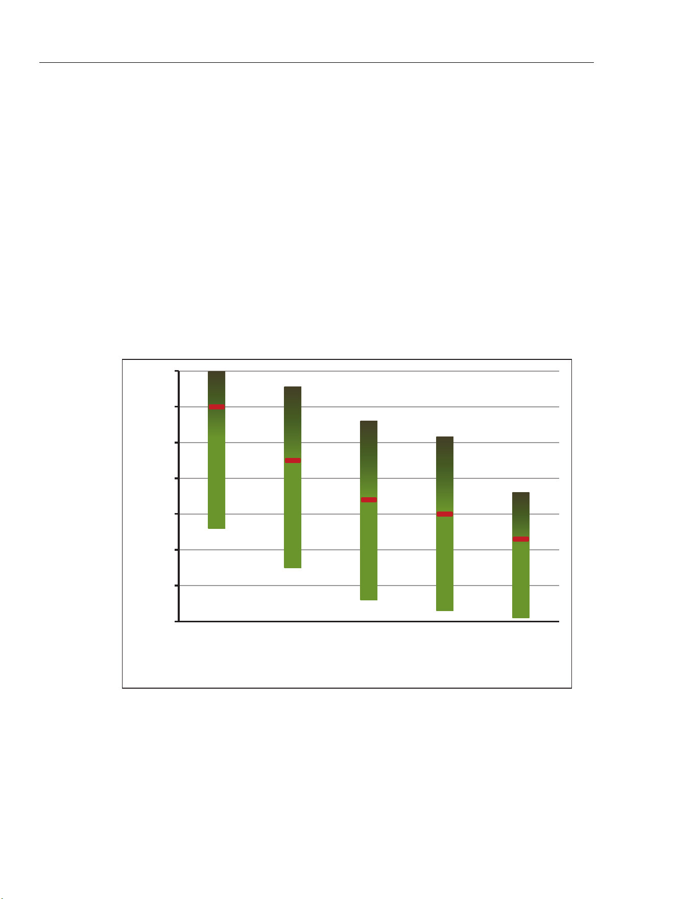
6109A/7109A
Operators Manual
78
Disposal
Whatever fluid is used, devise a proper disposal plan to ensure that the fluid is
discarded in a legal and environmentally friendly manner.
Silicone Fluids
A silicone fluid is usually the best choice for the Product. Silicone products are
available with a variety of temperature ranges and viscosities. As a general rule,
choose the fluid with the highest temperature range without exceeding
50 centistokes viscosity at the lowest temperature at which it will be used.
Figure 15 shows the temperature ranges of several types of silicone fluid
supplied by Fluke Calibration. Fluke model numbers identify the fluids. Nominal
viscosity at 25 °C is shown below the model number. The minimum temperature
is the point at which viscosity is about 50 centistokes when the fluid is new. The
maximum temperature is just below the flash point. The red line indicates the
oxidation point, above which the life of the fluid is reduced. At the top of the
range the fluid may emit heavy fumes. Recommended fluids are 5012 for the
7109A and 5014 for the 6109A.
-50
0
50
100
150
200
250
300
5017
(500 cst)
5014
(50 cst)
5013
(20 cst)
5012
(10 cst)
5010
(5 cst)
Temperature (°C)
Fluke Fluid Number
5014
(50 cst)
5012
(10 cst)
icu13.eps
Figure 15. Silicone Fluid Temperature Ranges
1.888.610.7664 sales@GlobalTestSupply.com
Fluke-Direct.com

Portable Calibration Baths
Customer-Replaceable Parts and Accessories
79
Customer-Replaceable Parts and Accessories
Accessories can be purchased separately. They are delivered in a separate
carton. Optional accessories are shown in Table 14.
Table 14. Customer Replaceable Parts and Accessories
Description Model Fluke Part Number
Silicone fluid, 10 centistoke (for 7109A) 5012-3.8L 2430079
Silicone fluid, 50 centistoke (for 6109A) 5014-3.8L 2430135
Fluid overflow kit 7109-2080 4810215
Single Probe clamp kit 7109-2051 4810226
Adjustable probe fixture 7109-2027 4810232
Probe access cover 7109-2013-2 4810259
Carrying case 7109-CASE 4810267
RS-232 cable 2200962
Transport cover 7109-2013-1 4810244
USB cable 3724037
Din connector (-P models) 3707630
Test lead kit (-P models) 2530650
Input Module fuse (5x20, 50 mA, 250 V) 3719614
Safety information sheet 4684061
CD 4684077
Mains power cord See Figure 6
1.888.610.7664 sales@GlobalTestSupply.com
Fluke-Direct.com
