
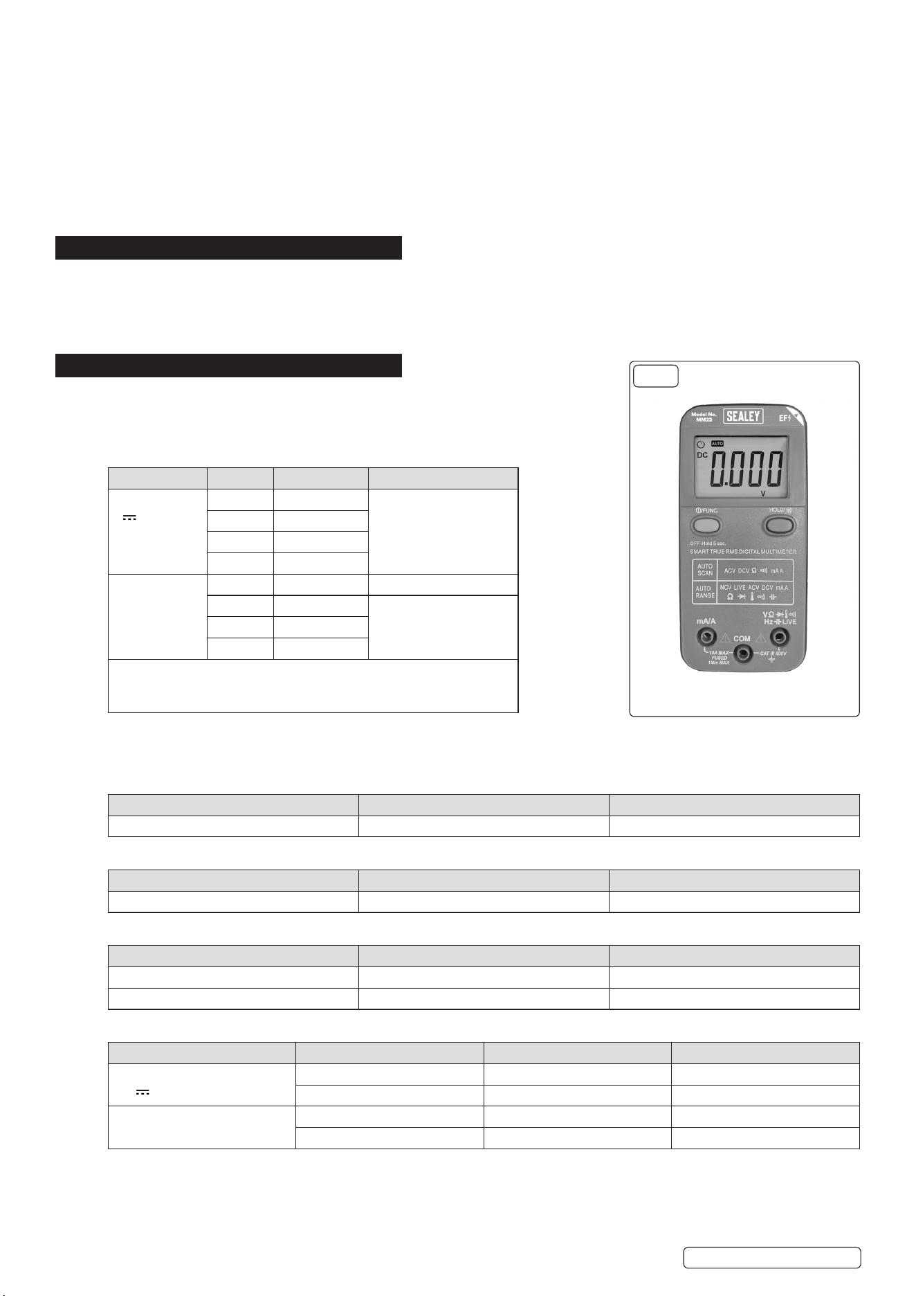
13-FUNCTION PROFESSIONAL SMART AUTO-
SCANNING DIGITAL MULTIMETER
MODEL NO: MM22
Thank you for purchasing a Sealey product. Manufactured to a high standard, this product will, if used according to these instructions,
and properly maintained, give you years of trouble free performance.
IMPORTANT: PLEASE READ THESE INSTRUCTIONS CAREFULLY. NOTE THE SAFE OPERATIONAL REQUIREMENTS, WARNINGS &
CAUTIONS. USE THE PRODUCT CORRECTLY AND WITH CARE FOR THE PURPOSE FOR WHICH IT IS INTENDED. FAILURE TO DO
SO MAY CAUSE DAMAGE AND/OR PERSONAL INJURY AND WILL INVALIDATE THE WARRANTY. KEEP THESE INSTRUCTIONS SAFE
FOR FUTURE USE.
1. SAFETY
1.1. GENERAL SAFETY
9 Perform a risk assessment of tasks to be carried out before using the meter.
9 Measurement category III is for the measurements performed on circuits directly connected to the low voltage installation. This meter
has been designed according to IEC-61010-1 concerning electronic measuring instruments with an overvoltage category (CAT III 600V)
and pollution degree 2.
9 Please ensure that these guidelines are followed to guarantee the optimal performance and safety of our meter and the user.
9 Follow all safety and operating instructions to ensure the meter is used safely and is kept in good condition. With proper use and care,
your digital multimeter will give you years of satisfactory service.
9 When using this multimeter, please observe all normal safety rules concerning protection against the dangers of electrical current, and
protection of the meter against misuse.
9 Full compliance with safety standards can only be guaranteed if used with the test leads supplied. If necessary, they must be replaced
with genuine Sealey leads and/or those with the same electrical ratings. Failure to do so will invalidate the warranty.
8 DO NOT use leads if damaged or if the wires are bared in any way.
1.2. DURING USE
8 NEVER exceed the protection limit indicated in the specications for each range of measurement.
8 NEVER use the meter to measure voltages that might exceed 600V above earth ground in category III installations.
9 Always be careful when working with voltages above 60V dc or 30V ac rms. Keep ngers behind the probe barriers while measuring.
8 DO NOT perform resistance measurements on live circuits.
9 Inspect test leads and probes for cracks, breaks or crazes in the insulation before using the meter.
9 Familiarise yourself with the application and limitations of the multimeter as well as the potential hazards.
9 This meter is designed to be used outdoors in dry conditions in accordance with Overvoltage Category III and Pollution Degree 2
IF IN ANY DOUBT CONSULT A QUALIFIED ELECTRICIAN.
WARNING! USE EXTREME CAUTION WHEN WORKING WITH HIGH VOLTAGES.
8 DO NOT position the equipment so it is dicult to disconnect the probes.
9 When the meter is connected to a circuit, DO NOT touch unused meter terminals.
9 When the magnitude of the value to be measured is unknown, set the range selector to the highest value available.
9 Before commencing testing, follow instructions below and select the correct input sockets, function and range on the multimeter.
9 Before changing functions, disconnect the test leads from the circuit under test.
9 Take care when working with voltages above 35V DC or 25V AC rms. These voltages are considered a shock hazard.
9 Keep ngers behind the probe barriers whilst measuring.
8 DO NOT test voltages above 600V - the circuitry of the multimeter may be destroyed.
WARNING! NEVER connect the multimeter to a voltage source / live circuit when the rotary switch is set to any other function apart
from voltage testing.
WARNING! NEVER perform resistance, transistor, diode or continuity measurements on live circuits.
9 Always discharge lter capacitors in power supplies and disconnect the power when making resistance or diode tests.
WARNING! Voltage checks on electrical outlets can be dicult and misleading because of the uncertainty of connection to the
recessed electrical contacts. Other means should be used to ensure that the terminals are not “live”.
8 DO NOT use the multimeter in a potentially explosive atmosphere.
8 DO NOT operate the meter unless the back cover and the battery and fuse doors are in place and fastened securely.
9 If any abnormal readings are observed, the multimeter must be checked out by an authorised technician.
9 When not in use, store the multimeter carefully in a safe, dry, childproof location out of direct sunlight. Storage temperature range is
-10 to 60°C (14°F to 140°F)
9 Always turn o the power and disconnect the test leads before opening the doors to replace the fuse or batteries.
9 The user shall ensure that test probes are correctly selected in order to prevent danger. Probes shall be selected to ensure that
adequate barriers guard against inadvertent hand contact with live conductors under test and that probes have minimal exposed probe
tips. Where there is a risk of the probe tip short circuiting with other live conductors under test, it is recommended that the exposed tip
length shall not exceed 4mm.
NOTE: The warnings, cautions and instructions referred to in this manual cannot cover all possible conditions and situations that may occur.
It must be understood that common sense and caution are factors which cannot be built into this product, but must be applied by the operator.
Refer to
instructions
Electrical shock
hazard
Keep in dry area
protect from rain
Warning
Original Language Version
© Jack Sealey Limited
MM22 Issue 4 (3) 15/07/24
1.3. MAINTENANCE SAFETY
9 Before opening case, always disconnect test leads from all energized circuits.
9 For continuous protection against re, replace fuse only with ratings: F 10A /600V Ø6x30 (Quick Acting)
8 NEVER use the meter unless the back cover is closed completely.
8 DO NOT use abrasives or solvents on the meter. To clean it use only a damp cloth and mild detergent.
1.4. PROBE ASSEMBLY OPERATION
9 If the probe assembly is used in a manner not specied by the manufacturer, the protection provided by the probe assembly may be
impaired.
9 The applicable measurement category of a combination of a probe assembly and an accessory is the lower of the measurement
categories of the probe assembly and of the accessory.
9 Inspect the probes for damage to ensure safe use.
2. INTRODUCTION
High-precision Smart auto-scanning multimeter. The intelligent multimeter automatically detects and selects the required test function,
AC/DC, voltage/current, resistance and continuity. Confirms to EN 61010-1 CATIII 600V safety requirements for electrical equipment for
measurement, control and laboratory use. Features temperature measurement capability, data hold and auto-power-off function. Non-
contact voltage detection (NCVD) enables one-handed use. The live test feature can test for live feeds with a single probe. Supplied with
probes including a thermocouple probe and integral upright stand for use on the workbench. Clear and easy-to-read LCD display.
3. SPECIFICATION
Accuracy is specied for one year after calibration, at operating temperatures of 18
o
C to
28
o
C, with relative humidity at 0% to 75%. Accuracy specications take the form of: ±(% of
Reading + Number of Least Signicant Digits)
3.1. VOLTAGE
FUNCTION RANGE RESOLUTION ACCURACY
DC Voltage
V
4.000V 1mV ±(0.5% of rdg +3
Digits)
40.00V 10mV
400.0V 100mV
600V 1V
AC Voltage1,2
V~
4.000V 1mV ±(1.0% of rdg + 6 digits)
40.00V 10mV ±(1.0% of rdg + 3 digits)
400.0V 100mV
600V 1V
1. Frequency Range: 40Hz to 1kHz RMS.
2. AC minimum measurement: 5% of lowest range;
3. Overload Protection: 600V dc or 600V ac rms.
When the testing environment is below CAT III, the meter can meet the range of 50-1000V
for non-contact voltage detect and 100-1000V for LIVE test. In both cases they are not connecting ground or neutral.
3.2. NON-CONTACT VOLTAGE DETECT
VOLTAGE FREQUENCY INDICATION
50 to 1000V 50Hz to 400Hz 4Bars display/ Alarm light/Beep
3.3. LIVE TEST
VOLTAGE FREQUENCY INDICATION
100 to 1000V 50Hz to 400Hz “H” display/ Alarm light/Beep
3.4. TEMPERATURE MEASUREMENT (K-TYPE THERMOCOUPLE)
RANGE RESOLUTION ACCURACY
-200 to 1200
o
C 1
o
C ±(2% of rdg +3 digits)
-328 to 2192
o
F 1
o
F ±(2% of rdg +6 digits)
3.5. CURRENT
FUNCTION RANGE RESOLUTION ACCURACY
DC Current
mA
4000mA 1mA ±(1% of rdg+3 digits)
10.00A 10mA ±(1.5% of rdg+3 digits)
AC Current
mA ~
4000mA 1mA ±(1.5% of rdg+3 digits)
10.00A 10mA ±(2% of rdg+3 digits)
FIG.1
Original Language Version
© Jack Sealey Limited
MM22 Issue 4 (3) 15/07/24
Overload protection:
10A range: Maximum input 10A DC or AC RMS. F 10A/600V fuse.
Over Load indication: OL Displayed.
>1A for 1min load on then 10min load o.
Ensure terminal sockets have a good connection.
3.6. RESISTANCE
FUNCTION RANGE RESOLUTION ACCURACY
Resistance
Ω
400.0Ω 0.1Ω ±(0.5% of rdg+3 digits)
4.000kΩ 1Ω ±(0.5% of rdg+2 digits)
40.00kΩ 10Ω
400.0kΩ 100Ω
4.000MΩ 1kΩ
40.00MΩ 10kΩ ±(1.5% of rdg+3 digits)
Overload protection: 600V DC or 600V AC rms.
3.7. CONTINUITY CHECK
FUNCTION RANGE RESOLUTION DESCRIPTION
Continuity Test 200.0Ω 0.1Ω Continuity beeper ≤ 50Ω
Overload protection: 600V AC or 600V DC rms.
Test Condition: Open circuit voltage: approx. 0.5V
3.8. DIODE TEST
FUNCTION RANGE RESOLUTION ACCURACY
Diode Test 1.000 V 0.001V 1.0% uncertainty
Overload protection: 600V DC or 600V AC rms.
Test Condition: Forward DC current approximately 1mA.
Reversed DC voltage approximately 1.5V
3.9. CAPACITANCE
FUNCTION RANGE RESOLUTION ACCURACY
Capacitance 4.000nF 1pF ±(5.0% of rdg+30 digits)
40.00nF 10pF ±(3.0% of rdg+5 digits)
400.0nF 0.1nF
4.000μF 1nF
40.00μF 10nF
400.0μF 0.1uF
1.000mF 1uF
Overload protection: 600V DC or 600V AC rms. (Auto range only.)
3.10. LINEAR FREQUENCY
RANGE RESOLUTION ACCURACY
10.00 to 40.00Hz 0.01Hz ±(0.5% of rdg+3 digits)
40.0 to 400.0Hz 0.1Hz
400 to 4000Hz 1Hz
Overload protection: 600V DC or 600V AC rms.
Cannot accept below 10Hz and Over 1KHz.
Original Language Version
© Jack Sealey Limited
MM22 Issue 4 (3) 15/07/24
3.11. SCAN SMART MEASURE MODE RANGE
FUNCTION RANGE
DC Voltage 0.700V to 600.0V
AC Voltage 0.700V to 600.0V
Resistance 50.0Ω to 40.00MΩ
Continuity 0.0 to 50.0Ω
DC Current 1mA to 10.00A
AC Current 4mA to 10.00A
Please check accuracy at above function tables.
3.12. GENERAL SPECIFICATIONS
Environment conditions: 600V CAT III
MAX. Voltage between terminals and earth ground: 600 V AC rms or 600V DC
Pollution degree: 2
Altitude: < 2000m
Operating temperature: 0 to 40
o
C (32
o
F to 104
o
F)
Storage temperature: -10 to 60
o
C (14
o
F to 140
o
F)
Fuse Protection: F 10A/600V ø6x30 (Quick Acting)
Sample Rate: 3 times/sec for digital data.
Display: 3999 LCD display. Automatic indication of functions and symbols.
SMART/SCAN function: Auto recognize measurement function (AC or DC Voltage/Resistor/Continuity/
AC or DC Current).
Range selection: Automatic
Over Range indication: Display “OL”
Low battery indication: Yes
Polarity indication: “−” displayed automatically
Hazardous voltage indication: >36V “ >36V displayed
Current Mis-plug alarm: Alarm light/Beep
Auto Power o: 30 Minutes
Backlight and Alarm light and Flashlight: Yes
Battery type: 3V, AAA x2
Dimensions (L x W x H): 130 x 62 x 26mm
Weight: 138g approx. (battery included)
4. OPERATION
DO NOT position the equipment so that it is dicult to operate the disconnecting device.
4.1. SCAN (SMART) MEASUREMENT MODE
Select SCAN using the FUNC. Key. Connect the black lead and red test leads plug to the COM and V terminals. NOTE: when
measuring current, the red test lead must plug into the mA/A terminal. Connect the test leads probe to the target. The device will select
the mode according to the target (AC or DC Voltage/Resistor/Continuity/AC or DC Current).
4.2. DC VOLTAGE
Select DCV using the FUNC. Key. Connect the black and red test leads plug to the COM and V terminal. Connect the test leads probe
to the target. Read the displayed value. NOTE: the reading will display negative if the probes are connected the wrong way around.
4.3. AC VOLTAGE
Select ACV using the FUNC. Key. Connect the black and red test leads plug to the COM and V terminal. Connect the test leads probe
to the target. Read the displayed value.
4.4. RESISTANCE MEASUREMENT
Select Resistance using the FUNC. Key. Connect the black and red test leads plug to the COM and V terminal. Connect the test leads
probe to the target. Read the displayed value. DO NOT input a Voltage source at this mode.
Probe Specication
Voltage 600V
Measurement Category Category III
Probe Symbols
Hazardous voltage Caution - Read Instructions
Conforms to
standard
Double Insulated
Original Language Version
© Jack Sealey Limited
MM22 Issue 4 (3) 15/07/24
4.5. AUDIBLE CONTINUITY TEST
Select Continuity using the FUNC. Key. Connect the black and red test leads plug to the COM and V terminal. Connect the test
leads probe to the target. The meter will show the resistance of the connection. When the circuit is below 50Ω, a continuous beep will
sound. DO NOT input a Voltage source at this mode.
4.6. CURRENT MEASUREMENT
Turn o power to the circuit. Discharge all high voltage capacitors. Connect the black and red test leads to the COM and mA/A terminal.
Use the FUNC. Key to select DCA or ACA measure mode. Break the circuit path to be tested. Touch the black probe to the negative
side of the break; touch the red probe to the positive side of the break. NOTE: reversing the leads will give a negative reading, but
will not damage the multimeter. Turn on power to the circuit; then read the display. Turn o power to the circuit and discharge all high
voltage capacitors. Remove the Meter and restore the circuit to normal operation.
4.7. CAPACITANCE MEASUREMENT
Use the FUNC. Key to select Capacitance measure mode. Connect the black and red test leads plug to the COM and V terminal.
Connect the test leads probe to the target. Read the displayed value. Discharge all high voltage capacitors before measure. DO NOT
input a voltage source at this mode.
4.8. FREQUENCY MEASUREMENT
Use the FUNC. Key can select Frequency measure mode. Connect the black and red test leads plug to the COM and V terminal.
Connect the test leads probe to the target. Read the displayed value.
4.9. TEMPERATURE MEASUREMENT
Use the FUNC. Key to select Temperature measure mode. Connect the K-type thermocouple sensor to COM and V terminal and read
the displayed value.
4.10. DIODE TEST
Use the FUNC. Key to select Diode measure mode. Connect the black and red test leads plug to the COM and V terminal. Connect
the test leads probe to the target. Red test lead connection will be positive. The meter will show the approx. forward voltage of the
diode. DO NOT input a voltage source at this mode.
4.11. LIVE TEST (ONLY ONE RED TEST LEAD PLUG IN)
Hold the meter by hand. Hold the FUNC. Key for 3 seconds, then press FUNC. Key once to select LIVE test function. Connect the red
test lead plug to the V terminal. (Only need one RED test lead). Connect the red test leads to the circuit being measured. “Hi” will been
shown when connect the red test leads to LIVE wire.
4.12. NON-CONTACT VOLTAGE DETECT (NCV/EF) TEST
Hold the FUNC. Key for 3 seconds to select NCV function. Make upper right corner of device (marking NCV) close
to test wire/socket. It will showing 4 bars according LIVE voltage level and distance.
4.13. HOLD KEY / BACKLIGHT KEY
Press once for Data Hold function. This will stop the meter from updating the display. Hold for 3 seconds for backlight
and ashlight on/o.
4.14. FUNC KEY / RANGE KEY
Press once to switch between SCAN function, DCV, ACV, Resistance, Continuity, Diode, Capacitance, Frequency,
Temperature. Hold for 3 seconds for Into/Exit EF/LIVE test mode
4.15. AUTO POWER OFF FUNCTION
The Meter enters “sleep mode” if the Meter is on but not used for 30 minutes. Hold for 5 seconds “HOLD” key
then Press “ON/OFF” key to turn on meter, meter will disable auto power o function, auto power o symbol will
disappear.
4.16. CURRENT PLUG-IN DETECT
When a test lead is plugged in at the mA/A terminal, then any measurement function will be changed to current
measurement function.
4.17. VOLTAGE ALARM
A lightning symbol will be displayed if the device is receiving a hazardous voltage >36V.
5. MAINTENANCE
WARNING! Ensure test leads have been disconnected before opening the casing. Close and secure casing before reuse.
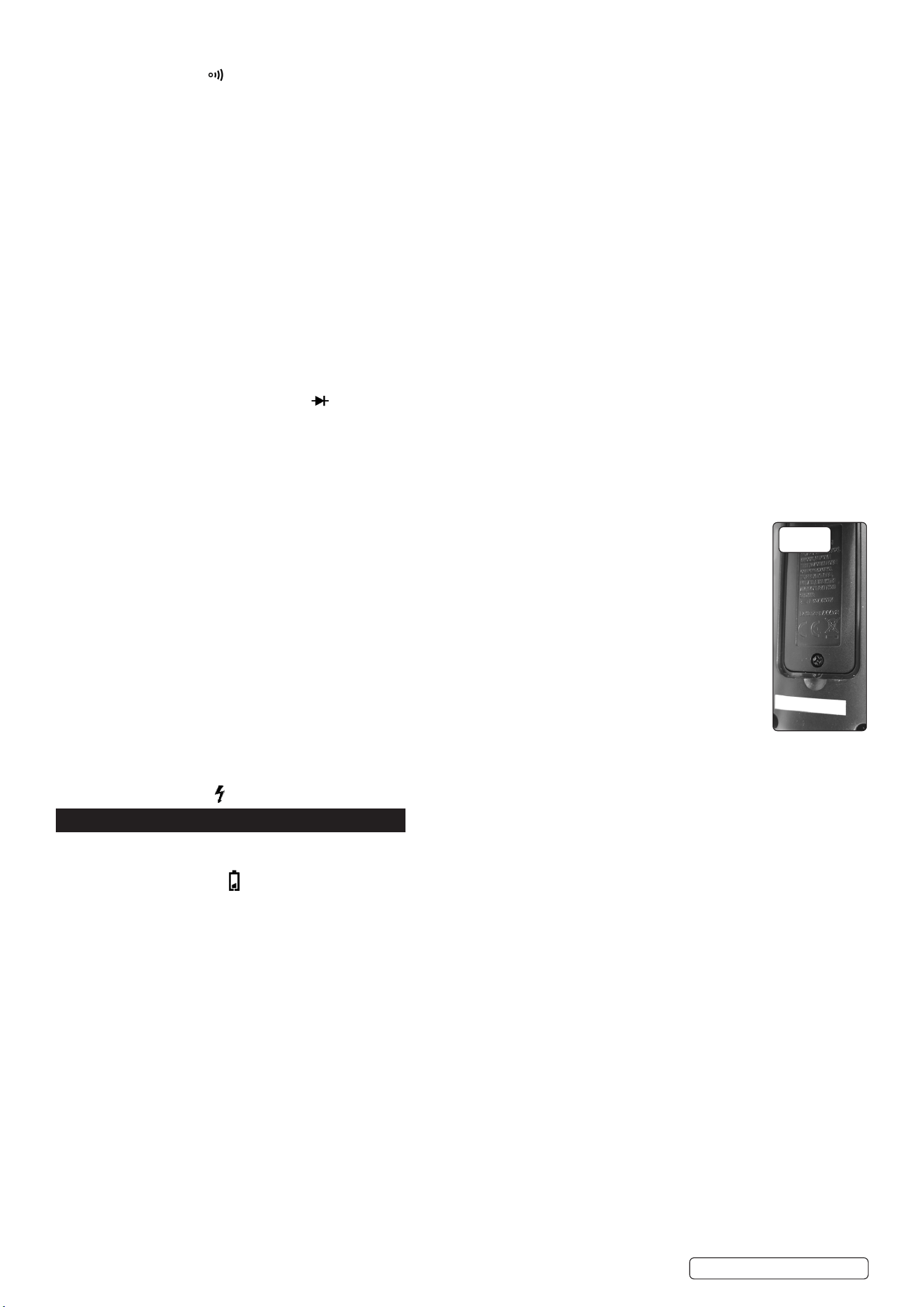
5.1. BATTERY REPLACEMENT (FIG.2)
If the battery symbol appears on the LCD display, the battery should be replaced. Remove the screw on the back cover and open
the battery case. Replace the exhausted batteries with two new 1.5V batteries of the same type (AAA). Close and secure casing before
reuse.
5.2. FUSE REPLACEMENT
The fuse rarely needs replacement. A blown fuse is normally a result of the operators error. Open the case and replace the blown fuse
with the same rating specied: F 10A/600V Ø6x30. Close and secure casing before reuse.
5.3. PROBE / TEST LEAD REPLACEMENT
DO NOT use if the probe, test leads or wires are damaged. DO NOT repair. Use suitable replacement parts only.
Original Language Version
© Jack Sealey Limited
FIG.2
MM22 Issue 4 (3) 15/07/24
Sealey Group, Kempson Way, Suffolk Business Park, Bury St Edmunds, Suffolk. IP32 7AR
01284 757500 sales@sealey.co.uk www.sealey.co.uk
Note: It is our policy to continually improve products and as such we reserve the right to alter data, specications and component parts without prior notice.
Important: No Liability is accepted for incorrect use of this product.
Warranty: Guarantee is 12 months from purchase date, proof of which is required for any claim.
ENVIRONMENT PROTECTION
Recycle unwanted materials instead of disposing of them as waste. All tools, accessories and packaging should be
sorted, taken to a recycling centre and disposed of in a manner which is compatible with the environment. When
the product becomes completely unserviceable and requires disposal, drain any uids (if applicable) into approved
containers and dispose of the product and uids according to local regulations.
REGISTER YOUR
PURCHASE HERE
WEEE REGULATIONS
Dispose of this product at the end of its working life in compliance with the EU Directive on Waste Electrical and Electronic
Equipment (WEEE). When the product is no longer required, it must be disposed of in an environmentally protective way. Contact
your local solid waste authority for recycling information.
BATTERY REMOVAL
Under the Waste Batteries and Accumulators Regulations 2009, Jack Sealey Ltd are required to inform potential purchasers of products
containing batteries (as defined within these regulations), that they are registered with Valpak’s registered compliance scheme. Jack
Sealey Ltd Batteries Producer Registration Number (BPRN) is BPRN00705.
Original Language Version
© Jack Sealey Limited
MM22 Issue 4 (3) 15/07/24