
AUTO DARKENING WELDING HELMET WITH TH3
POWERED AIR PURIFYING RESPIRATOR (PAPR)
MODEL NO: PWH615
Thank you for purchasing a Sealey product. Manufactured to a high standard, this product will, if used according to these
instructions, and properly maintained, give you years of trouble free performance.
I
MPORTANT:
PLEASE READ THESE INSTRUCTIONS CAREFULLY. NOTE THE SAFE OPERATIONAL REQUIREMENTS, WARNINGS & CAUTIONS. USE
THE PRODUCT CORRECTLY AND WITH CARE FOR THE PURPOSE FOR WHICH IT IS INTENDED. FAILURE TO DO SO MAY CAUSE DAMAGE AND/OR
PERSONAL INJURY AND WILL INVALIDATE THE WARRANTY. KEEP THESE INSTRUCTIONS SAFE FOR FUTURE USE.
1. SAFETY
WARNING! This helmet is not suitable for use with laser welding or CUTTING or for overhead welding applications.
9 Ensure all workshop safety rules, regulations and conditions are complied with when using welding equipment. The helmet will not o er
protection against misuse of workshop tools, equipment, or accessories.
9 Maintain the helmet in good condition and protect cartridge from liquid and dirt contact. Regularly replace the protective lens and
replace any damaged or worn parts. Use genuine parts only. Unauthorised parts may be dangerous and will invalidate the warranty.
9 Ensure the front cover window is securely in place before use.
9 Fit the helmet and adjust the head band so the helmet will sit as low and near to your face as possible.
9 Use helmet only in temperatures ranging from -5°C to 55°C.
9 Remove ill tting clothing, remove ties, watches, rings and other loose jewellery.
9 Maintain correct balance and footing.
9 Ensure the oor is clear from obstructions, not slippery and wear non-slip protective shoes.
9 Keep children and unauthorised persons away from the working area.
WARNING! The helmet will only protect the eyes and face from radiation and sparks. It will not protect against explosive devices or
corrosive liquids.
8 DO NOT use helmet for any purpose for which it is not designed.
8 DO NOT use helmet unless you have been instructed in its use by a quali ed person.
8 DO NOT open or tamper with the shade cartridge.
8 DO NOT get the helmet wet or use in damp or wet locations.
8 DO NOT leave work place with helmet in lowered position, as bright light source may darken cartridge unexpectedly.
8 DO NOT place the helmet on a hot surface.
8 DO NOT use helmet without front cover window tted. To do so will invalidate your warranty.
9 Clean helmet (see section 5.5) and store the helmet in a safe, dry, childproof location.
WARNING! Before welding always inspect the cartridge lter to ensure that it is not damaged. To test the lter prior to welding, direct
the front of the cartridge lter to a bright light source which will cause the lens to darken. Then using your hand rapidly cover and
uncover the sensor. The lter should lighten momentarily then return to a dark state.
WARNING! DO NOT use the helmet if damaged or you suspect it may be faulty. (Contact Sealey Stockist).
▲ DANGER! DO NOT use if, at any time, the face plate in the cartridge FAILS to darken when exposed to a welding spark. Remove
cartridge and return to your Sealey stockist for checking.
9 Continued use of the product knowing that the auto darkening feature is NOT FUNCTIONING may DAMAGE YOUR EYES and CAUSE
BLINDNESS.
▲ DANGER! DO NOT wear this respirator system to enter areas where:
1. Atmospheres are oxygen de cient.
2. Contaminant concentrations are unknown.
3. Contaminant concentrations are Immediately Dangerous to Life or Health.
4. Contaminant concentrations exceed the maximum use concentration determined using the assigned Protection Factor for the
speci c respirator system.
WARNING! The Particle lter can not be cleaned. DO NOT attempt to remove contamination using for example compressed air as this
will destroy the lters, the equipment will not give the expected protection and the warranty will be invalidated.
9 If ventilation is poor, wear an approved air-supplied respirator.
9 Read and understand the Material Safety Data Sheets and the manufacturer’s instructions for metals, consumables, coatings,
cleaners, and degreasers.
9 Work in con ned space only if it is well ventilated, or while wearing an air-supplied respirator. Always have a trained watch-person
nearby. Welding fumes and gases can displace air and lower the oxygen level causing injury or death. Be sure the breathing air
is safe.
8 DO NOT weld in locations near degreasing, cleaning, or spraying operations. The heat and rays of the arc can react with vapours to
form highly toxic and irritating gases.
8 DO NOT weld on coated metals, such as galvanized, lead, or cadmium plated steel, unless the coating is removed from the weld area,
the area is well ventilated, and while wearing an air-supplied respirator. The coatings and any metals containing these elements can
give o toxic fumes if welded. RESPIRATOR (PAPR) MISUSE can be hazardous. Welding produces fumes and gases. Breathing these
fumes and gases can be hazardous to your health.
9 Read and follow these instructions and the safety labels carefully. The powered air purifying respirator (PAPR) helps protect the user
Refer to
instructions
Original Language Version
© Jack Sealey Limited
PWH615 Issue 3 (H,F) 02/08/23

from specic airborne contaminants but must be used correctly to be fully eective. Have an industrial hygienist test the air in your
facility to ensure the PAPR provides adequate protection from contaminants in your environment. If you have questions about the
respirator, see equipment warning label and consult your Safety Director and a certied Industrial Hygienist.
9 Follow all applicable EN/ANSI/CSA/AS&NZS, and other regulatory guidelines pertaining to the use of respirators.
8 DO NOT use the powered air purifying respirator where there is danger of re or explosion.
8 DO NOT use the powered air purifying respirator in windy conditions or negative pressure inside the hood may draw in contaminants
from the outside air.
8 DO NOT use the powered air purifying respirator without a properly installed spark guard cover. Without the spark guard cover,
welding sparks may ignite the lter, or damage the lter and allow unltered air into the helmet.
9 The powered air purifying respirator does not supply oxygen. Use the respirator only in atmospheres for which it is EN/ANSI/CSA/
AS&NZS approved.
8 DO NOT use the respirator where oxygen levels are 19.5% or lower, where contaminant levels are unknown or are immediately
dangerous to life or health, or where the contaminant levels exceed the respirator specications.
8 DO NOT enter a hazardous area until you are sure the respirator equipment is correctly assembled, working properly, and
properly worn.
9 Before each use, inspect the respirator equipment for damage and verify it operates properly. Before using the respirator, test air ow
to verify it is providing an adequate volume of air.
8 DO NOT use the powered air purifying respirator without all lter components or with the blower turned o, as hazardous levels of
oxygen and carbon dioxide may accumulate in helmet.
9 Always wear the powered air purifying respirator when entering a contaminated area. DO NOT remove the respirator until outside
the contaminated area.
9 Dangerous contaminants may not smell or be visible. Leave the area immediately if you notice the following:
- Breathing becomes dicult.
- You experience dizziness, impaired vision, or eye, nose, or mouth irritation.
- The powered air purifying respirator alarm sounds.
- The equipment is damaged.
- Air ow decreases or stops.
- If you think the equipment is not supplying adequate protection.
8 DO NOT remove the equipment until you are in a safe area.
8 DO NOT repair, modify, or disassemble the powered air purifying respirator or use with parts or accessories not supplied by the
manufacturer. Use only those components that are part of the approved assembly.
9 Replace damaged or clogged lters. DO NOT wash or reuse lters.
8 DO NOT clean lters by tapping or with compressed air or lter elements may be damaged. Dispose of used lter elements according
to local, state, and federal requirements.
9 The powered air purifying respirator must be used with the helmet, hood, and lters recommended by the manufacturer to provide a
respirator system. See the label on the blower for information on the required equipment.
8 DO NOT use the powered air purifying respirator belt or shoulder straps(if equipped) as a safety harness.
2. INTRODUCTION
PAPR (Powered Air-Purifying System) with Auto Darkening Welding Helmet with large viewing area. Lithium battery powered blower
unit gives the user a cooling stream of air to their head and face for up to 8 hours. The lter is designed to reduce or remove dust
and particles but not vapours and gases. The kit meets performance class TH3 (Less than 0.2% inward leakage) according to EN
12941:1998. Adjustable airow settings of 170 and 200L/min. Features a loud audible and visual alarm to alert user of low battery/low
air. The welding helmet has adjustable shade control from 9-13. Fully automatic switching from light to dark on striking arc. Additional
shades 5-8 for gas welding/cutting. Solar panel power supply. Features sensitivity and delay controls for switching light to dark.
Contoured design helmet with adjustable headband for added comfort. Suitable for MIG, TIG, MMA/ARC welding, cutting and grinding.
Complies with BS EN 379, BS EN 175, EN12941 and DIN standards.
3. SPECIFICATION
Model No: .........................................................PWH615
Grinding Function: ..................................................... Yes
Operating Temperature: ............................-5°C to +55°C
Operating Time Light/Dark: ................................... 0.1ms
Power: ............ Solar Cells/Rechargeable Lithium Battery
Shade Active: ................. 5-8 Switchable & 9-13 Variable
Shade Inactive: ............................................................. 4
Viewing Area: ..............................................120 x100mm
4. OPERATION
4.1. ADJUSTING THE HELMET
4.1.1. Adjust the headgear diameter with the twist knob on the back. The knob is locked until pushed in. Once unlocked, twist clockwise to
tighten and counter clockwise to loosen.
4.1.2. Adjust the height by snapping the pin on the top band into the hole to lock
securely in place.
4.1.3. To adjust the viewing angle, loosen the knob on both sides of the helmet
and change angle locker to the desired tilt position (5 selection and
positioned in the middle by default). Once achieving the desire angle,
tighten the knobs until snug. The helmet should still swing up, but it should
not drift downward when in place for welding.
4.1.4. To adjust the distance between the user’s face and ADF, loosen the
knobs on both sides of the helmet until the headband can move back and
forth freely, reposition the headband at one of the 3 slots as desired. The
headband is positioned in the middle by default. This should be done one
side at a time and both sides should be located at the same position for
proper auto-darkening lter operation.
Forward/
backward
adjustment
Push in
thumbwheel and
turn to adjust
circumference
Tilt
adjustment
A
i
r
T
u
b
e
Push in
thumbwheel and
turn to adjust
circumference.
g.1
Original Language Version
© Jack Sealey Limited
PWH615 Issue 3 (H,F) 02/08/23
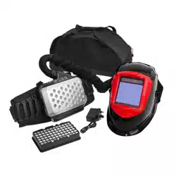
4.2. SHADE GUIDE TABLE
4.3. SELF-CHECK
4.3.1. Press the TEST Button at any time to see if it automatically switches to dark state and release it to check that the lter returns to the
light state. Shade Control; Select the shade DIN 9 to 13 based upon the welding process you will use by consulting the “Shade Guide
Table”. The variable shade control knob is for internal adjustment. The welding helmet can also be used to protect the face when
cutting, from shade DIN 5 to 8. Grind mode DIN 4 prevents lter lens from auto-darkening for grinding use.
4.4. SENSITIVITY CONTROL
4.4.1. The sensitivity can be set from LOW to HIGH by using the sensitivity dial. The LOW setting suits excess ambient light or with another
welding machine close by. The HIGH setting suits low amperage welding and welding in areas with low light conditions, especially low
amperage argon arc welding. Selections between LOW and HIGH are suitable for most of indoor and outdoor welding operations.
4.5. DELAY CONTROL
4.5.1. When welding ceases, the viewing window automatically changes from dark back to light but with a pre-set delay to compensate. The
delay time can be set from MIN (0.1 sec) to MAX (1.0 sec), by Shade Delay Control. The minimum delay suits spot or short welds. The
maximum delay suits heavy current welding and reduces eye fatigue from the arc. Selections between MIN and MAX are suitable for
most of indoor and outdoor welding operations.
4.6. CLEANING AND STORING
4.6.1. Keep the sensors, solar cell and lter lens clean. Clean lter cartridge and helmet shell by using a soapy water solution and soft cloth.
8 DO NOT use solvents or abrasive cleaning detergent. Switch the product to Grind Mode and put it in a clean, dry location for storage.
4.7. INSTALLING THE BATTERY
8 DO NOT allow battery to get wet.
8 DO NOT attempt to open the battery case.
9 Keep battery away from re or heat.
9 Charge battery before rst use.
4.7.1. Push the battery into blower body until battery snaps into position.
Press the button on the end to assist with this.
4.7.2. To release, push the button on the end in and pull out.
4.8. INSTALLING THE AIR FILTER
8 DO NOT use the respirator without the Foam Pre lter and HEPA
Filter installed ( g.4).
9 Replace damaged or dirty air lter.
4.8.1. Install the HEPA Filter into the cover. Install the Foam Pre lter
above the HEPA Filter. Push down the cover until it “clicks” into
position as shown.
NOTE: Filter Screen and Foam Pre lter protects and increases the
life time of the particle lter.
g.4
Battery CR2032
Battery CR2032
Shade Range Selection Switch
Test Button
Shade Delay Control
Sensitivity Control
Fine Shade Control
Grind/Weld Switch
g.3
g.2
Protective Cover
Foam Prefilter
Filter Screen
HEPA Filter
Blower Body
Blower Body Outlet
g.4
Original Language Version
© Jack Sealey Limited
PWH615 Issue 3 (H,F) 02/08/23
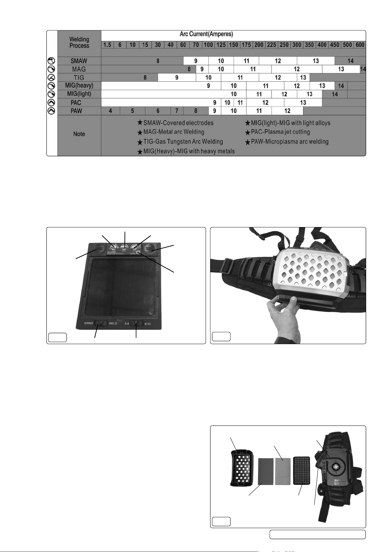
4.9. ATTACHING THE BREATHING TUBE
4.9.1. Insert tube connector into blower body outlet until snug and then turn connector 1/8 turn to the right to lock it into place (g.6).
4.9.2. Insert the breathing tube terminal 1 into the headgear terminal and turn the tube clockwise until breathing tube locks in position.
4.10. TEST AIR FLOW
4.10.1. Disconnect breathing tube from hood. Insert owmeter into breathing tube (g.7). Hold owmeter straight up and start blower.
4.10.2. The owmeter ball should oat above minimum mark. If owmeter reads minimum or below, please check battery and lter
elements (g.5).
4.11. TESTING AIR FLOW ALARM
4.11.1. Disconnect breathing tube from hood. Start blower and block air ow by placing your hand over the end of breathing tube. Continue
blocking air ow until alarm sounds and the blower vibrates. If alarm does not sound and the blower does not vibrate, check battery and
lter element.
4.12. OPERATING THE CONTROLS (FIG.8)
4.12.1. TO START: Press On button for 1 second until the blower starts. The Danger ,Low Speed, High Speed Indicator lights go on, then go
out, the alarm sounds, and the blower vibrates momentarily. Then the blower always starts at the low speed. Press the SELECT button
to switch between low and high speeds.
4.12.2. TO STOP: Press O button for 1 second until the audible alarm and blower stop. The Danger Indicator light goes on, the alarm
sounds, and blower vibrates if battery power is low or air ow is reduced due to a dirty lter, blocked breathing tube, or other problem.
4.13. BATTERY LEVEL INDICATOR LIGHT
Green light goes on: battery level ≥ 90%
Yellow light goes on: 30% ≤ battery level < 90%
Red light goes on: 10% < battery level < 30%
Red light ash: battery level ≤10%
4.14. CHECKING THE RESPIRATOR BEFORE USE
Before using the respirator, check the following items:
9 Face seal; Inspect the face seal and replace if damaged.
9 Air Filter Assembly; Verify the air lter is suitable for the application. Also be sure the lter is undamaged, and securely connected to
the blower assembly.
9 Breathing Tube; Be sure the tube is undamaged and properly connected to the blower assembly and hood.
9 Battery; Verify the battery is fully charged and securely connected to the blower assembly.
9 Air Flow; Test air ow according to Section 4.10.
9 Air Flow Alarm; Turn on blower assembly and check for audible, visual, and vibratory alarms.
9 Hood; Inspect the hood and replace if damaged.
5. MAINTENANCE
5.1. FRONT COVER LENS REPLACEMENT
5.1.1. Replace the front cover lens if it is damaged (cracked, scratched, pitted or dirty). Remove the old front cover lens by pressing two
lock switches at the bottom of the retaining frame and pull the frame and ADF out. Take the old front cover lens out, and remove any
protective lm before installing the new one.
5.2. INSIDE COVER LENS REPLACEMENT
5.2.1. Replace the inside cover lens if it is damaged (cracked, scratched, pitted or dirty). Place your nger or thumb into the recess and ex
the inside cover lens upwards until it releases from one edge. Then remove any protective lm before installing the new one.
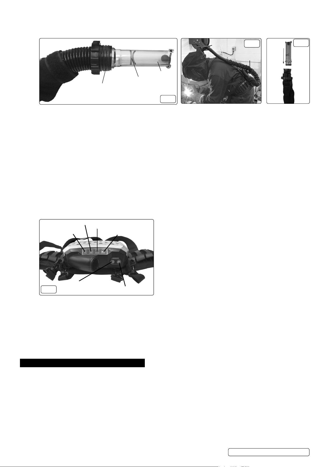
5.3. BATTERIES REPLACEMENT
5.3.1. When Low Voltage Indicator turns red, you have to change the batteries. Replace batteries by removing ADF from the retaining frame.
Slide cover plates on the top left and right, and replace the old batteries with lithium batteries. After that, put on cover plates of batteries
and install ADF back to frame (g.9).
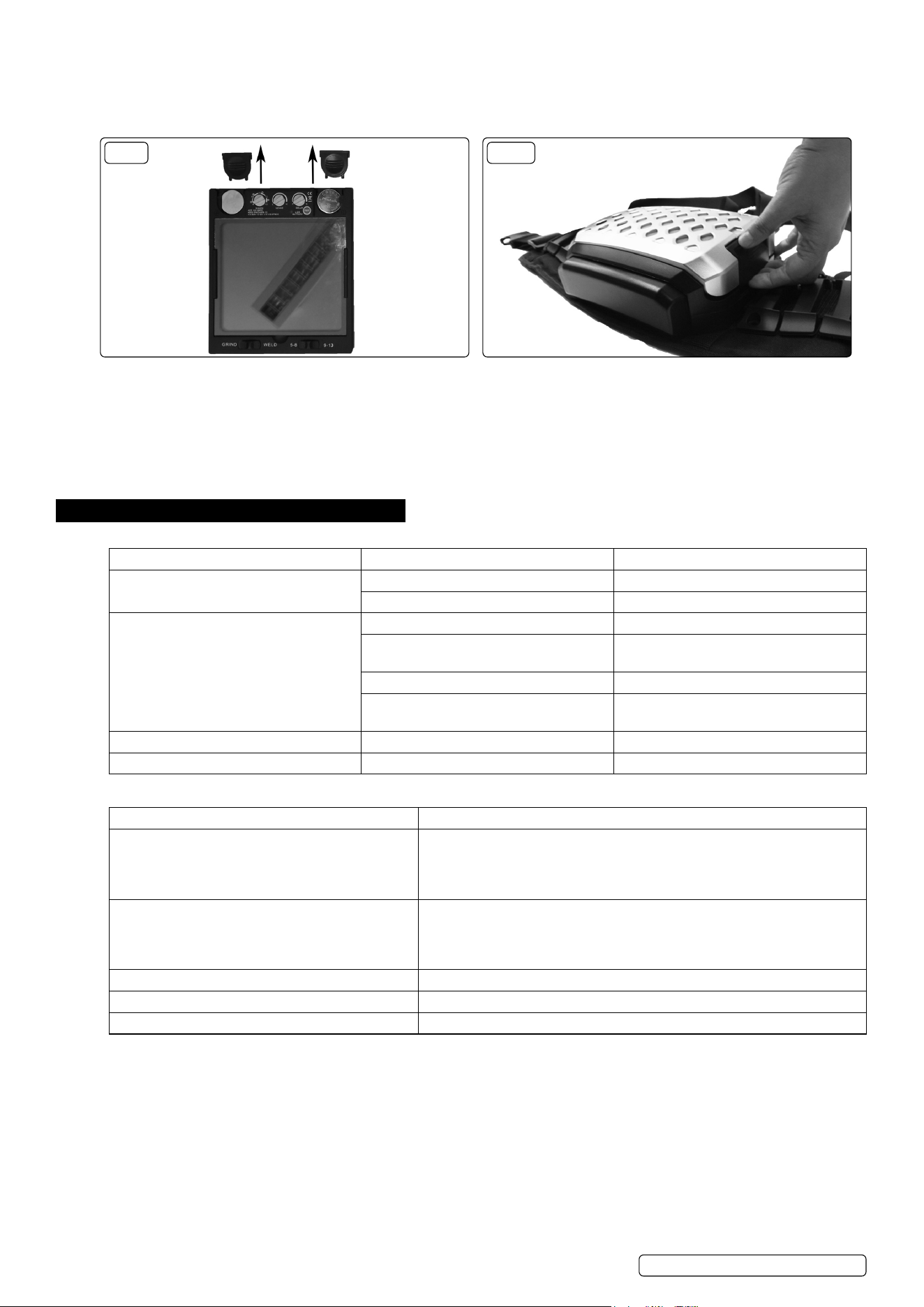
5.4. REPLACING THE FILTERS
5.4.1. Push down the cover until it “clicks”into position as shown (g.10), lift the top cover and remove the lter.
Air Flow Meter
Minimum Mark
Breathing Tube Connector
g.5
Breathing Tube Connector
and Terminal
Blower Unit
g.6
g.7
Low Speed Indicator
High Speed Indicator
Power On/Off
Low/High Selection
Danger Indicator
Battery Level Indicator
g.8
Original Language Version
© Jack Sealey Limited
PWH615 Issue 3 (H,F) 02/08/23
5.5. CLEANING:
5.5.1. Detach the battery pack, breathing tube and the blower. Inspect all parts for damage. Replace all damaged parts prior to storage or
next use.
A. Blower: Clean the outer surfaces of PAPR assembly and battery pack with a soft cloth dampened in a solution of water and mild, pH
neutral detergent. DO NOT immerse the blower or battery pack in water. DO NOT use solvents or abrasive cleaners. DO NOT attempt
to clean the interior of the blower with compressed air or vacuum. Ensure the electrical contacts of the blower and battery pack are dry.
B. Breathing tube: Clean the connection sites on the breathing tube with the water and detergent solution. The breathing tube can be
immersed in water for cleaning. The inside of the tube must be completely dried prior to use or storage. Air dry, or dry by connecting to
the blower unit and use it to force air through the tube until dry.
C. HEPA lter: Open the lter cover and inspect the HEPA lter. Replace if excessively dirty.
5.6. STORAGE:
If the blower will not be used for an extended period, remove the lter and battery and store them in a clean, dry, cool place free of
solvent-based vapours.
6. TROUBLESHOOTING
6.1. WELDING SHIELD:
PROBLEM POSSIBLE CAUSES SUGGESTED SOLUTIONS
Dicult to see through lter Cover lens dirty Clean or replace cover lens
Filter lens dirty Clean lter lens
Filter does not darken when arc is struck Grind Mode Selected Adjust to ‘Weld’ mode.
Sensors or Solar Panel blocked Make sure sensors or solar panel are
exposed to weld arc without blocking
Set Sensitivity to LOW Adjust Sensitivity to required level
Low voltage of lithium batteries Replace with new lithium batteries if
indicator turns red
Filter darkens without arc Set Sensitivity to HIGH Adjust Sensitivity to required level
Filter remains dark after welding Set Delay to MAX Adjust Delay to required level
6.2. FILTER AND HOOD:
FAULT POSSIBLE SOLUTION
Blower does not supply air to hood 1. Press on to start blower
2. Recharge battery
3. Verify battery is properly connected to blower
4. Remove blockage from blower outlet and breathing tube
Battery pack’s charge lasts less than expected 1. Ensure battery pack is fully charged
2. Replace battery
3. Replace charger
4. Check the air lter(HEPA lter & Foam prelter) ,and replace it if necessary
Blower cannot be turned o Press ON/OFF button for one second
Battery red level light is ashing Charge or replace the battery
Danger light is on, alarm sounds or blower vibrates Check the blower air ow as section 4.10
g.9
g.9 g.10
Original Language Version
© Jack Sealey Limited
PWH615 Issue 3 (H,F) 02/08/23
Sealey Group, Kempson Way, Suffolk Business Park, Bury St Edmunds, Suffolk. IP32 7AR
01284 757500 sales@sealey.co.uk www.sealey.co.uk
WEEE REGULATIONS
Dispose of this product at the end of its working life in compliance with the EU Directive on Waste Electrical and Electronic Equipment
(WEEE). When the product is no longer required, it must be disposed of in an environmentally protective way. Contact your local solid
waste authority for recycling information.
BATTERY REMOVAL
Under the Waste Batteries and Accumulators Regulations 2009, Jack Sealey Ltd are required to inform potential purchasers of products
containing batteries (as defined within these regulations), that they are registered with Valpak’s registered compliance scheme. Jack
Sealey Ltd’s Batteries Producer Registration Number (BPRN) is BPRN00705.
Note: It is our policy to continually improve products and as such we reserve the right to alter data, specifications and component parts without prior
notice.
Important: No Liability is accepted for incorrect use of this product.
Warranty: Guarantee is 12 months from purchase date, proof of which is required for any claim.
Original Language Version
© Jack Sealey Limited
PWH615 Issue 3 (H,F) 02/08/23
ENVIRONMENT PROTECTION
Recycle unwanted materials instead of disposing of them as waste. All tools, accessories and packaging should be sorted,
taken to a recycling centre and disposed of in a manner which is compatible with the environment. When the product
becomes completely unserviceable and requires disposal, drain any fluids (if applicable) into approved containers and
dispose of the product and fluids according to local regulations.
REGISTER YOUR
PURCHASE HERE