Hydronic Air Handler Installaon and Operaon Manual 1
•
•
•
•
•
•
•
•
•
•
2 Hydronic Air Handler Installaon and Operaon Manual
Hydronic Air Handler Installaon and Operaon Manual 3
• You must read the entire manual to
properly operate the air handler.
• It is recommended that a trained and
qualified professional who has attended a
Rinnai installation training class complete
your installation.
• Keep this manual for future reference.
Dealer Name:
Located on front of unit
Dealer Phone:
Purchase Date:
Serial #:
Thank you for purchasing Rinnai’s hydronic air
handler.
Before installing and operating the hydronic air
handler, be sure to read these instructions
completely and carefully to familiarize yourself
with the features and functionality.
This manual provides instructions for installing
the hydronic air handler and is a supplement
to the Rinnai Tankless Water Heater or Boiler
Installation and Operations Manual supplied
with the system.
The air handler must satisfy all the
requirements in the Tankless Water Heater or
Boiler Installation and Operations Manual, as
well as the requirements in this manual.
• It is recommended that a trained and
qualified professional who has attended
a Rinnai installation training class install
the air handler, inspect it, and leak test it
before use. Improper installation may
void the warranty.
• The trained and qualified professional
should have skills such as:
− Connecting water lines, valves,
electricity
− Knowledge of applicable national,
state, and local codes
− Installing ductwork and other
HVAC equipment
− Training in installation of air
handlers. Training on Rinnai’s
hydronic air handler is accessible
at www.rinnai-lms.com.
• Read all instructions in this manual
before installing the hydronic air
handler. The hydronic air handler must
be installed according to the exact
instructions in this manual.
• When installation is complete, leave this
manual with the air handler or give the
manual directly to the consumer.
• Proper installation is the responsibility of
the installer.
4 Hydronic Air Handler Installaon and Operaon Manual
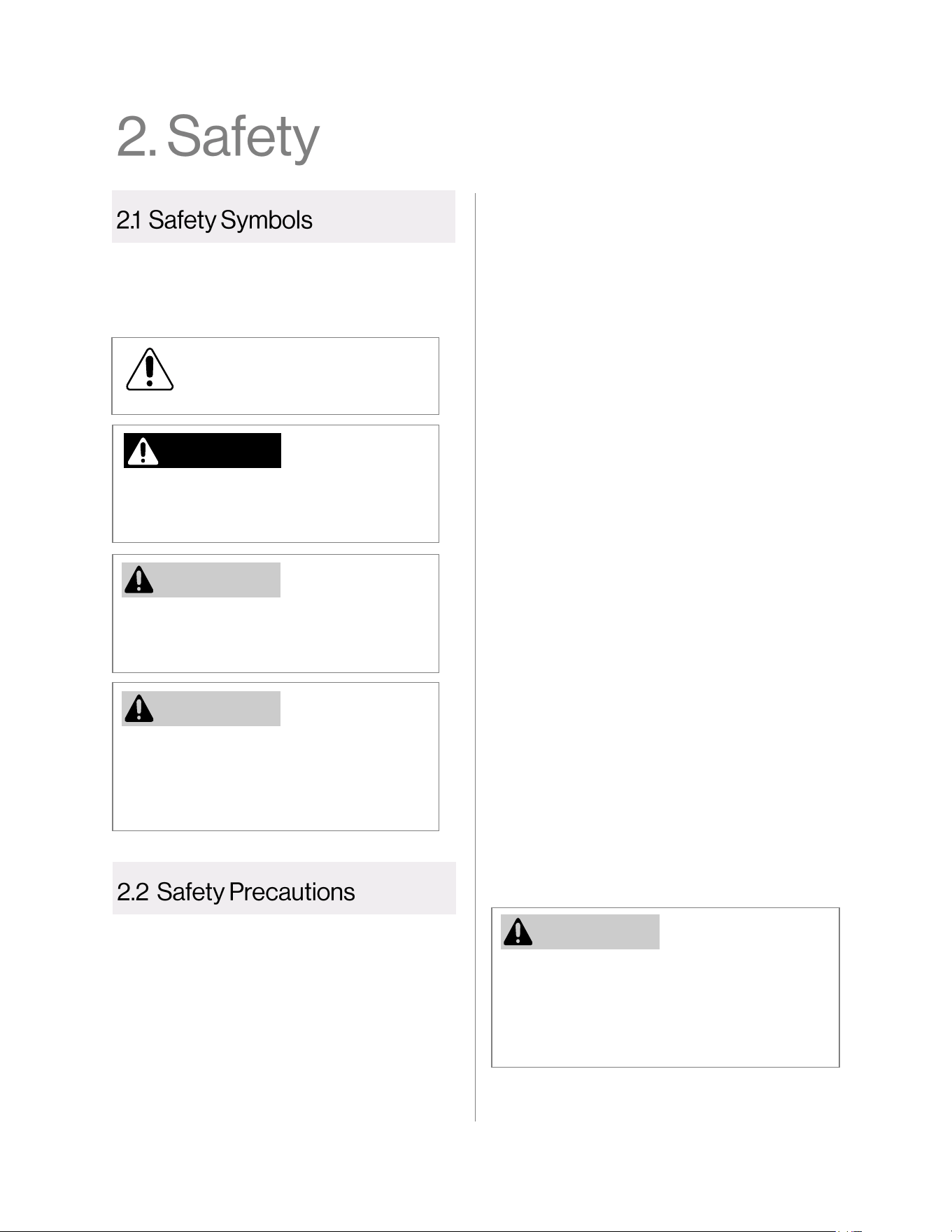
Indicates an imminently hazardous
situation which, if not avoided, will result
in personal injury or death.
Indicates a potentially hazardous situation
which, if not avoided, could result in personal
injury or death.
Indicates a potentially hazardous situation
which, if not avoided, could result in minor
or moderate injury. It may also be used to
alert against unsafe practices.
DANGER
WARNING
This manual contains the following important
safety symbols. Always read and obey all safety
messages.
Safety alert symbol. Alerts you to
potential hazards that can kill or
hurt you and others.
CAUTION
The following precautions apply to the installer
and consumer. Read and follow all instructions in
this section.
• Before any work is undertaken, it is
imperative to observe all precautions as
stated in this manual.
• Wear safety glasses and work gloves.
Before installing or servicing the air handler,
turn off the power to unit. There may be more
than one disconnect switch. Electrical shock
can cause personal injury or death.
WARNING
• Suitable fire extinguishing equipment should
be immediately available in the work area
and be maintained in a state of readiness for
instant use.
• Do not use this air handler if any part has
been under water. Immediately call a
licensed professional to inspect the air
handler and replace any part that has been
under water.
• Do not use substitute materials. Use only
parts certified for the air handler.
• Do not use an extension cord or adapter plug
with this air handler.
• Any alteration to the air handler can be
dangerous and will void the warranty.
• This air handler must be installed indoors.
• Improper installation, modification, service,
maintenance or use of the air handler can
cause electrical shock, burns or other
conditions which may cause personal injury
or property damage.
• It is recommended that a trained and
qualified professional who has attended a
Rinnai installation training class complete
your installation.
• Read these installation instructions carefully
and adhere to all warning and caution
statements. Consult local building codes,
Occupational Safety and Health
Administration (OSHA), and National
Electrical Code (NEC) for special
requirements.
Hydronic Air Handler Installaon and Operaon Manual 5
The hydronic air handler is designed to work
with Rinnai tankless water heaters and boilers
(models listed below) to deliver a wide variety
of heating capacities for residential and light
commercial applications.
The hydronic air handler works with the following
Rinnai products:
• Rinnai Tankless Water Heaters:
− SENSEI™ SE+ Series
(RU Condensing Models)
− HE+ Series
(RL Non-Condensing Models)
− HE Series
(V Non-Condensing Models)
It is the responsibility of the installer to follow all
national codes, standards and local ordinances,
in addition to the instructions in this manual. The
installation must comply with regulations of the
local building, heating, plumbing, and other
codes. Where local codes are not applicable, the
installation must comply with the national codes
and all authorities having jurisdiction.
The following is a suggested list of codes and
standards for the United States and Canada:
General Installation
• Installation of Air Conditioning and
Ventilating Systems NFPA 91 (latest edition)
Duct Systems
• Sheet Metal and Air Conditioning
Contractors National Association (SMACNA)
• American Society of Heating, Refrigeration,
and Air Conditioning Engineers (ASHRAE)
• 2001 Fundamentals Handbook Chapter 34
or 2000 HVAC Systems and Equipment
Handbook Chapters 9 and 16
• US and CANADA: Air Conditioning
Contractors Association (ACCA) Manual D
Acoustical Lining and Fibrous Glass Duct
• US and CANADA: Current edition of
SMACNA; NFPA 90B as tested by UL
Standard 181 for Class I Rigid Air Ducts
Electrical Connections
• US: National Electrical Code (NEC) ANSI/
NFPA 70 (latest edition)
• CANADA: Canadian Electrical Code CSA
C22.1 (latest edition)
Plumbing Systems
• US and CANADA: ICC International
Plumbing Code (IPC); Uniform Mechanical
Code (UMC); Uniform Plumbing Code (UPC)
Refer to section “3.8 Specifications” for a
complete list of product specifications.
NOTE
NOTE
Tankless water heaters must have a
minimum input rate of 160,000 Btu/hr.
• Rinnai Boilers:
− I-Series (Condensing) Combi Models
If utilizing a boiler, ensure the output of
the boiler exceeds the capacity of the
air handler in use (the boiler Btu/hr
rating must be greater than the air
handler Btu/hr rating).
NOTE
6 Hydronic Air Handler Installaon and Operaon Manual
When transporting components of the hydronic
air handler, follow the guidelines below:
• Choose the correct hand truck to support
the weight and size of the system
components. Refer to section “3.8
Specifications” for specific weights and
dimensions.
• Use safe lifting and material handling
principles to prevent workplace accidents.
• Use proper lifting techniques to load the
equipment onto a hand truck.
• Position the equipment onto the hand
truck so the weight is evenly balanced.
• Use personal protective equipment, such
as gloves and steel-toed boots.
If storing components of the hydronic air
handler, follow the guidelines below:
• Store system components in a clean, dry
environment.
• Components must be protected from
direct sunlight.
• Do not store components outdoors.
• If transported or stored at temperatures
below 32°F (0°C), the components must
be warmed up to 60°F (15°C) before the
start of assembly.
• All components must be stored in the
original packaging.
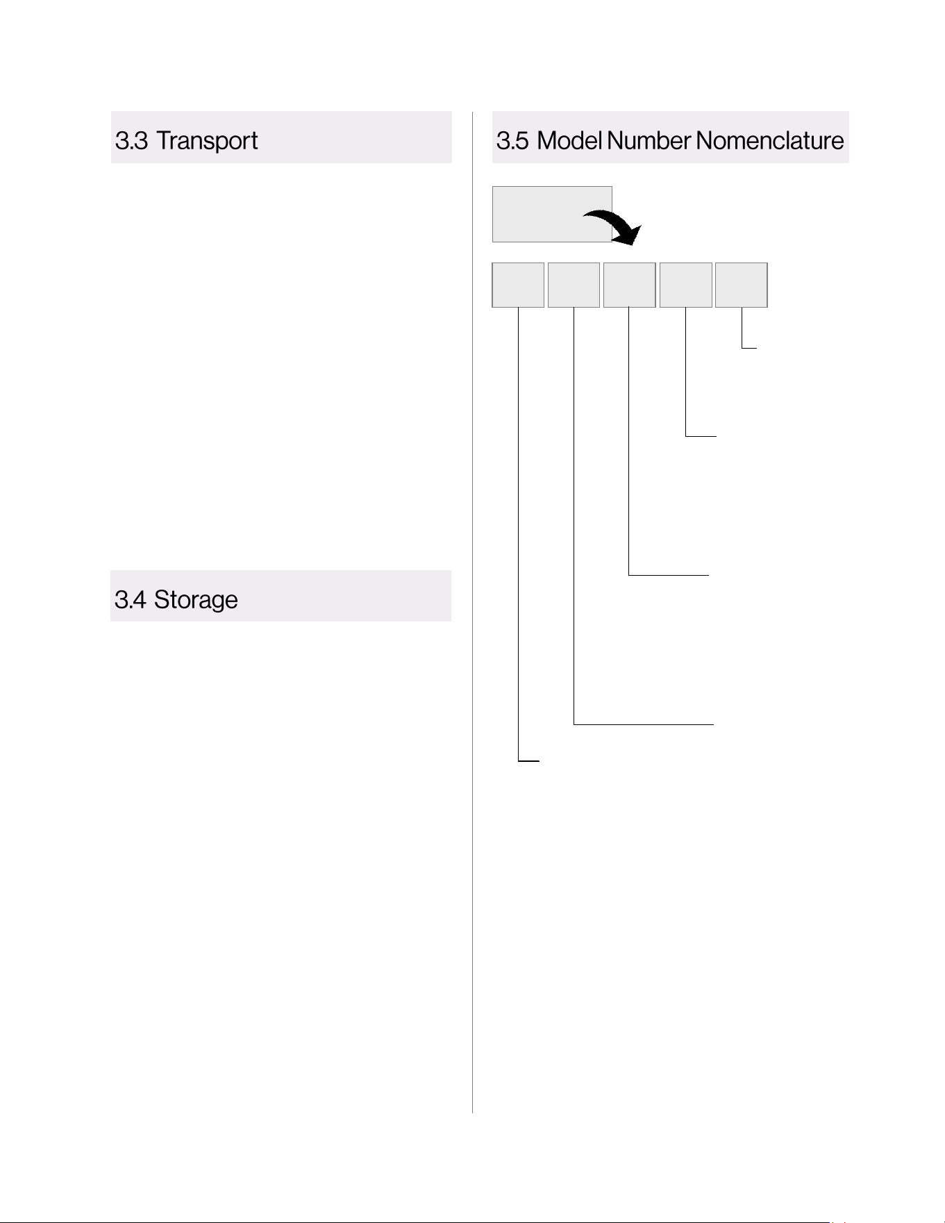
Example:
AH083CP
AH 08 3 C P
Blower Motor
P = 3-Speed
PSC Motor
Circulating Pump
C = Circulation Pump
Included
(Model numbers without a
“C” do not include an
internal circulation pump)
Nominal Heating Capacity
at 140° F
3 = 30,000 BTU
4 = 40,000 BTU
5 = 50,000 BTU
6 = 60,000 BTU
Size / Air Flow
08 = 800 CFM
12 = 1,200 CFM
16 = 1,600 CFM
20 = 2,000 CFM
Series
AH Series
Hydronic Air Handler Installaon and Operaon Manual 7
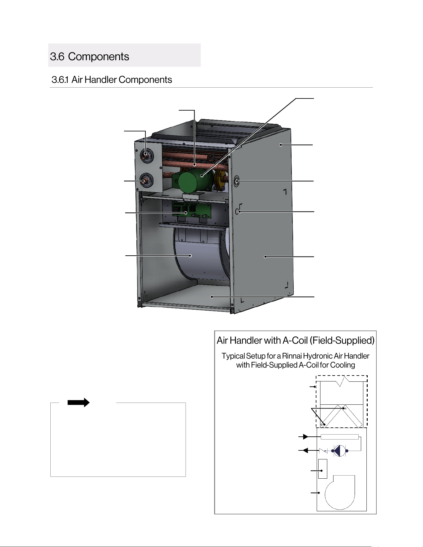
120V Power Supply
Knockout Access Port
1
24V Thermostat Cable
Knockout Access Port
(available on left or right
side)
Left or Right Side HVAC
Duct Return
Corrosion Resistant Cabinet
(made of heavy gauge
galvanized steel)
3-Speed PSC Blower
Motor and Housing
Control Panel
Water Inlet
Hot Water From Water Heater/
Boiler into Air Handler
Hydronic
Coil
Circulation Pump (for models
with integrated pump).
Circulates hot water between
the air handler and tankless
water heater/boiler.
Water Outlet
Cold Water Returning to
Water Heater/Boiler
Bottom HVAC
Duct Return
• Reference to the "top" and "bottom"
are referring to the location in this
image and will not change based on
orientation of the product.
• Cover is removed in above image to
show the air handler internal
components.
NOTE
TOP
BOTTOM
1
120V Power Supply Knockout Access Port:
• Located on right side panel for air handler
models AH083P/CP, AH084P/CP, AH125P/
CP, and AH166P/CP.
• Located on left side panel for air handler
models AH206P/CP.
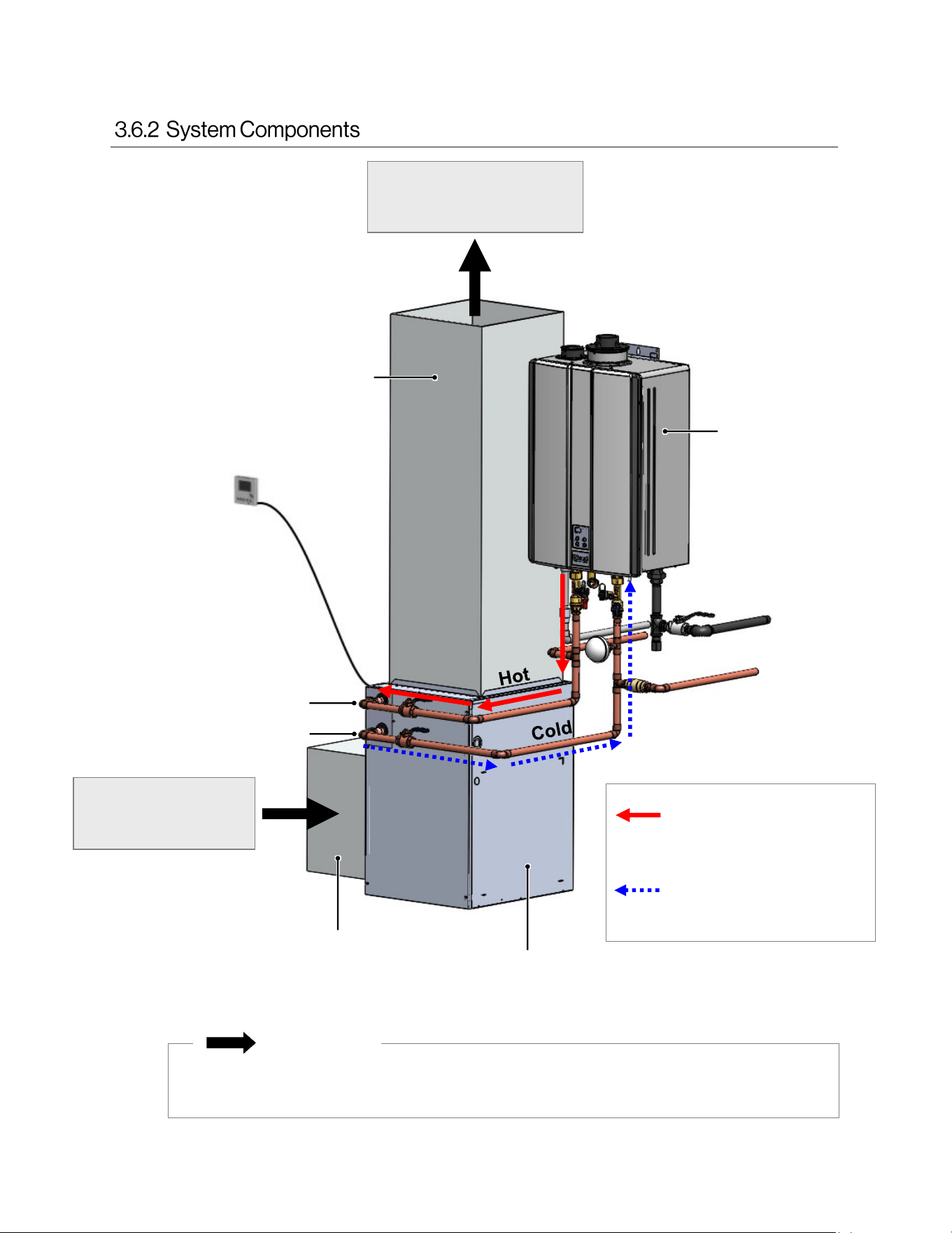
A-Coil and Ductwork
(Field-Supplied)
Control Panel
Air Handler
Water Outlet to
Water Heater/Boiler
Water Inlet From
Water Heater/Boiler
Refrigerant Lines (Field-
Supplied) to Condensing Unit
8 Hydronic Air Handler Installaon and Operaon Manual
The ductwork in the above image is for representation purposes only; it is not a
complete system. Please follow standard duct design protocols for installation.
RETURN
(Air Flows In)
SUPPLY
(Air Flows Out)
Thermostat
Supply
Ductwork
Return
Ductwork
Air Handler
Rinnai Tankless
Water Heater
or Boiler
Front
Panel
A call for heat from the
thermostat activates the
air handler
IMPORTANT
Water Inlet
Water Outlet
Hot Water From
Water Heater/Boiler
into Air Handler
Cold Water From
Air Handler Returning
to Water Heater/Boiler
Example Vertical (Upflow with
Side Return) Configuration
Hydronic Air Handler Installaon and Operaon Manual 9
• Upflow
The blower should be set on top of the coil
section being used and the blower must be
supported on the bottom only and set on
solid floor or a field-supplied supporting
frame.
• Side Return (Left or Right Side)
Cut and remove panel as indicated by
perforations. Attach evaporator coil with
sheet metal screws (if using). Ensure bottom
portion of unit is sealed properly to prevent
air leakage.
• Bottom Return
The air handler must be supported on the
underside only and set on a field-supplied
supporting frame. Remove the bottom plate
of the air handler to create an air return
opening. Securely attach the air handler to
the supporting frame.
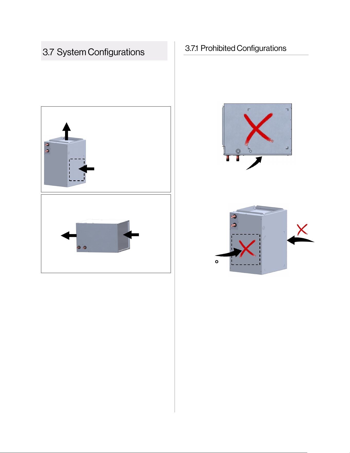
The air handler is approved for the following
configurations:
• Vertical: Upflow with bottom or side (left or
right side) return
• Horizontal: Upflow with bottom return
SUPPLY (Upflow)
RETURN
The air handler is not approved for the
following configurations:
• The air inlet is not allowed in the front
or back of the air handler.
Front
Back
• Multiple air handlers configured for
installation with a single Rinnai
tankless water heater or boiler is
prohibited.
• Do not position the air handler on its
front panel.
Front
Air flows in through bottom or
side (left or right side)
Vertical (upflow with bottom or side return)
Air flows out through top
Horizontal (Upflow with bottom return)
RETURN
Air flows in
through
“bottom
duct return”
SUPPLY
Air flows
out
through
“top”
10 Hydronic Air Handler Installaon and Operaon Manual
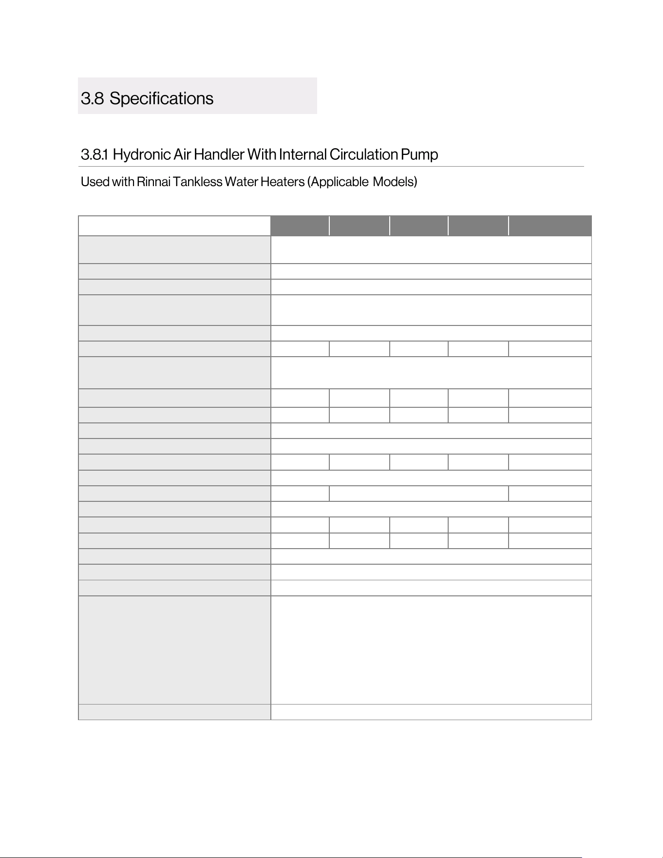
AH083CP AH084CP AH125CP AH166CP AH206CP
Appliance Type
Hydronic Air Handler
(With Internal Circulation Pump)
Installation Indoor (approved for manufactured housing and mobile homes)
Suitable for Potable Water Systems Yes
Configurations
• Vertical: Upflow with bottom or side (left or right side) return
• Horizontal: Upflow with bottom return
Circulation Pump Included Yes (Factory Installed)
Product Weight - lb. (kg) (approximate) 66 (30) 66 (30) 66 (30) 71 (32) 83 (38)
Cabinet Construction
Embossed cabinet in heavy gauge galvanized steel to prevent
corrosion. Cabinet lined with 5/8 in. foil faced insulation.
Nominal CFM (Cubic Feet/Minute)
800
800 1,200 1,600 2,000
Nominal Output Btu/hr at 140°F
1
30,000 40,000 50,000 60,000 60,000
Rated Voltage 120 V, 60 Hz, 1 Ph
Transformer Size and Type 40 VA, Class 2
Blower Wheel (Diameter x Width) 9x6 in. 9x6 in. 10x8 in. 10x8 in. 10x10 in.
Blower Motor Type 3-Speed PSC
Hot Water Coil Rows 3 4 3
Coil Material Copper Coil
Blower Motor Horsepower (HP) 1/3 1/3 1/2 3/4 3/4
Blower Full Load Amps (FLA) 5.3 5.3 7.1 7.5 10.5
Water Connection 3/4 in. Sweat
Pump Voltage 120 V
Pump Amps 1.4 Amps
Control Board
• Factory Installed
• Freeze protection activates at 40°F and deactivates at 70°F
• Thermostat connections
• 60-second time delay for blower activation
• Pump timer circulates water for one minute every six hours to
prevent stagnation of water in the system
• Boiler activation dry contact
• 24V AC isolation valve control
Certifications ETL Listed
Rinnai products are continually being updated and improved; therefore, specifications are subject to
change without prior notice.
1
Reference tables in sections 3.8.4 and 3.8.5 for specific BTU output.
Hydronic Air Handler Installaon and Operaon Manual 11
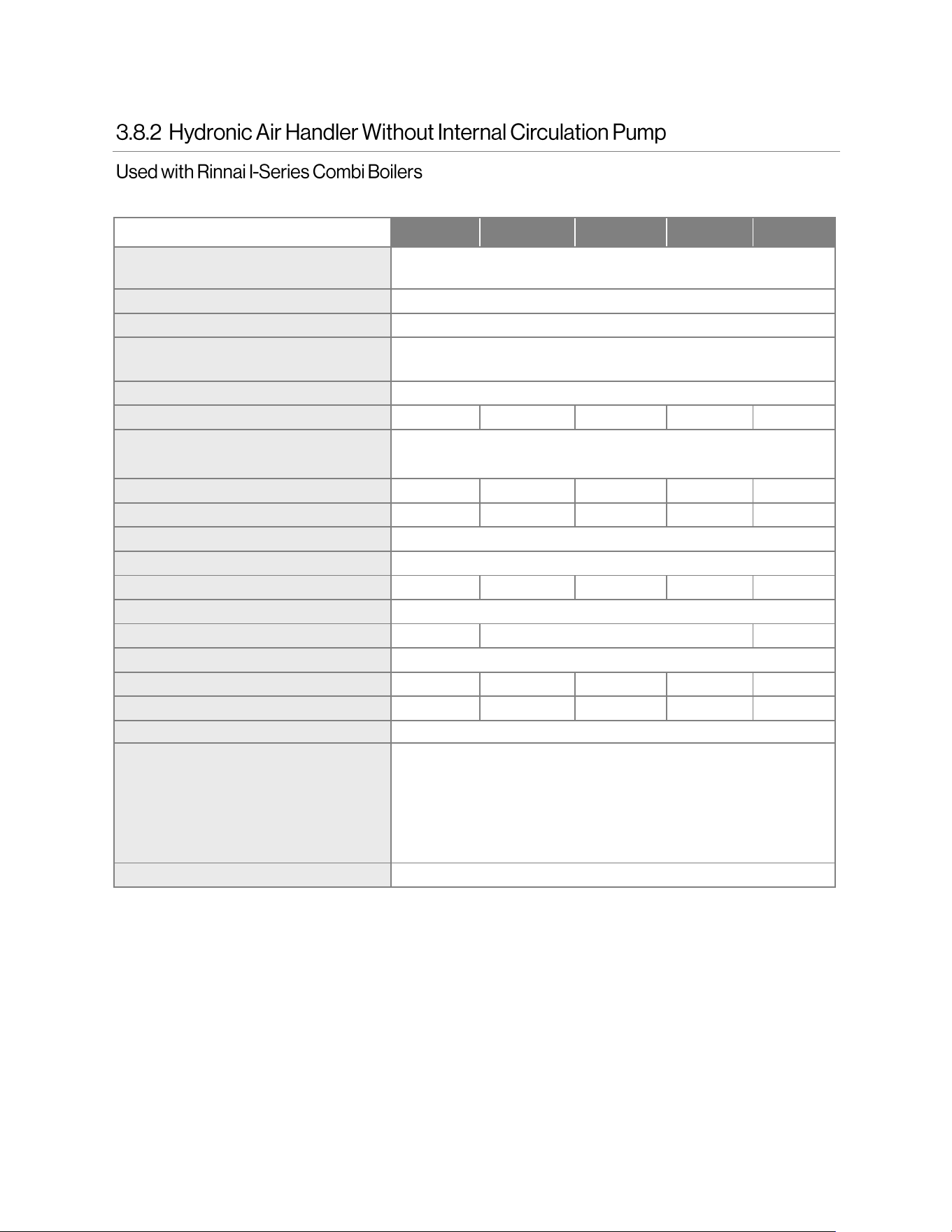
AH083P AH084P AH125P AH166P AH206P
Appliance Type
Hydronic Air Handler
(Internal Circulation Pump Not Included)
Installation Indoor (approved for manufactured housing and mobile homes)
Suitable for Potable Water Systems Yes
Configurations
• Vertical: Upflow with bottom or side (left or right side) return
• Horizontal: Upflow with bottom return
Circulation Pump Included No
Product Weight - lb. (kg) (approximate) 57 (26) 57 (26) 57 (26) 62 (28) 74 (34)
Cabinet Construction
Embossed cabinet in heavy gauge galvanized steel to prevent
corrosion. Cabinet lined with 5/8 in. foil faced insulation.
Nominal CFM (Cubic Feet/Minute) 800 800 1,200 1,600 2,000
Nominal Output Btu/hr at 140°F
1
30,000 40,000 50,000 60,000 60,000
Rated Voltage 120 V, 60 Hz, 1 Ph
Transformer Size and Type 40 VA, Class 2
Blower Wheel (Diameter x Width) 9x6 in. 9x6 in. 10x8 in. 10x8 in. 10x10 in.
Blower Motor Type 3-Speed PSC
Hot Water Coil Rows 3 4 3
Coil Material Copper Coil
Blower Motor Horsepower (HP) 1/3 1/3 1/2 3/4 3/4
Blower Full Load Amps (FLA) 5.3 5.3 7.1 7.5 10.5
Water Connection 3/4 in. Sweat
Control Board
• Factory Installed
• Freeze protection activates at 40°F and deactivates at 70°F
• Thermostat connections
• 60-second time delay for blower activation
• Boiler activation dry contact
• 24V AC isolation valve control
Certifications ETL Listed
Rinnai products are continually being updated and improved; therefore, specifications are subject to
change without prior notice.
1
Reference tables in sections 3.8.4 and 3.8.5 for specific BTU output.
12 Hydronic Air Handler Installaon and Operaon Manual
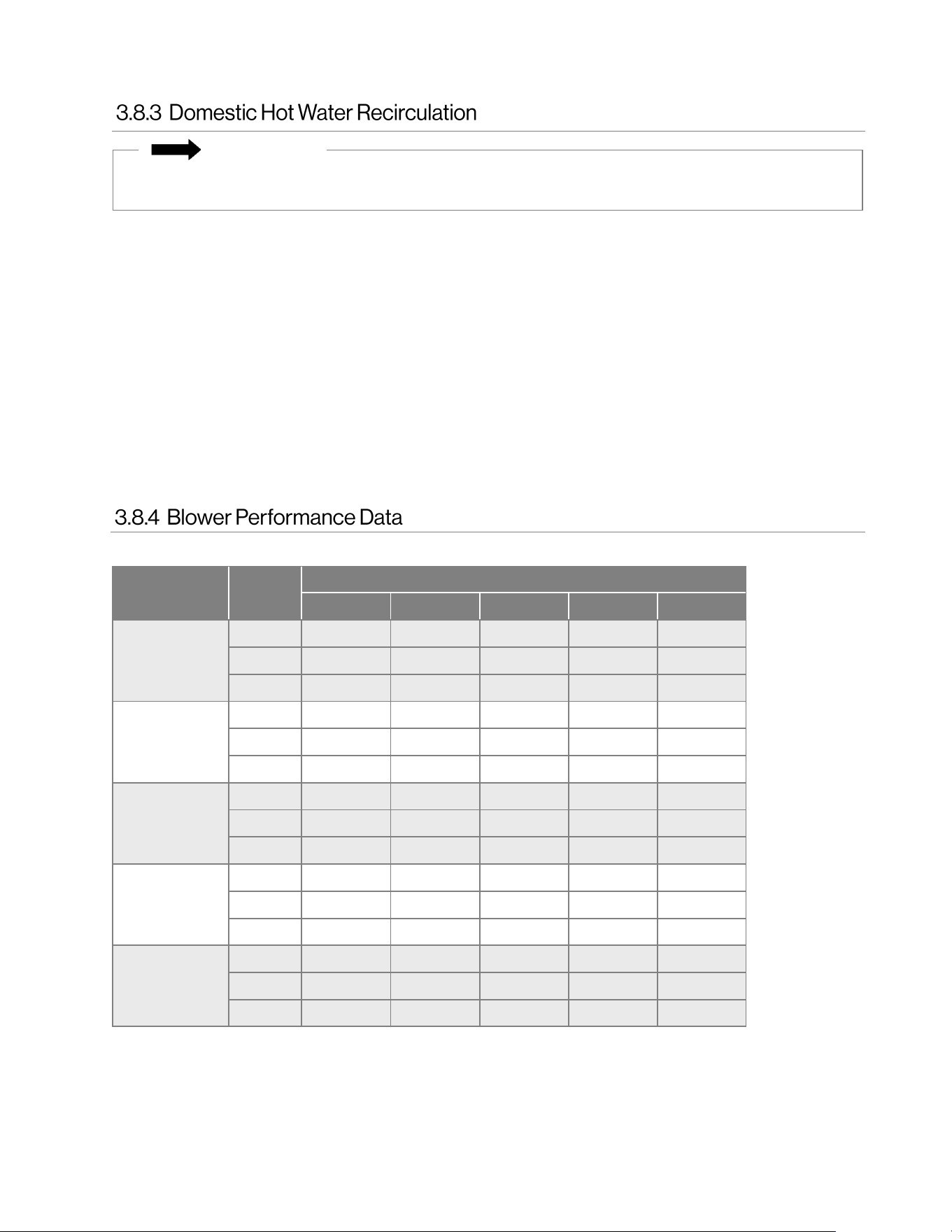
2
Factory default setting for both heating and cooling.
Air Handler
Models
Speed
Air Flow (CFM) vs External Static Pressure (WC)
0.1 0.2 0.3 0.4 0.5
AH083P
AH083CP
Low 749 705 658 614 558
Med
2
865 815 760 708 646
High 904 836 801 740 681
AH084P
AH084CP
Low 749 705 658 614 558
Med
2
865 815 760 708 646
High 904 836 801 740 681
AH125P
AH125CP
Low 1,198 1,144 1,086 1,018 962
Med
2
1,257 1,198 1,130 1,072 1,010
High 1,273 1,215 1,158 1,094 1,018
AH166P
AH166CP
Low 1,576 1,514 1,433 1,338 1,264
Med 1,643 1,576 1,490 1,407 1,320
High
2
1,707 1,606 1,545 1,441 1,364
AH206P
AH206CP
Low 1,759 1,691 1,652 1,580 1,512
Med 1,838 1,788 1,729 1,644 1,555
High
2
1,928 1,867 1,810 1,729 1,637
3-Speed PSC Motor Speed Table
• Results are obtained while air handler is operating with a dry DX coil and air filter installed.
• Values are nominal and blower performance can vary higher or lower from these values based on the
evaporator coil that is used. Hot water heat air flow performance data includes associated air pressure
drop across a four-row hot water coil for models AH084P/CP, AH125P/CP, and AH166P/CP, and air
pressure drop across a three-row hot water coil for models AH083P/CP and AH206P/CP.
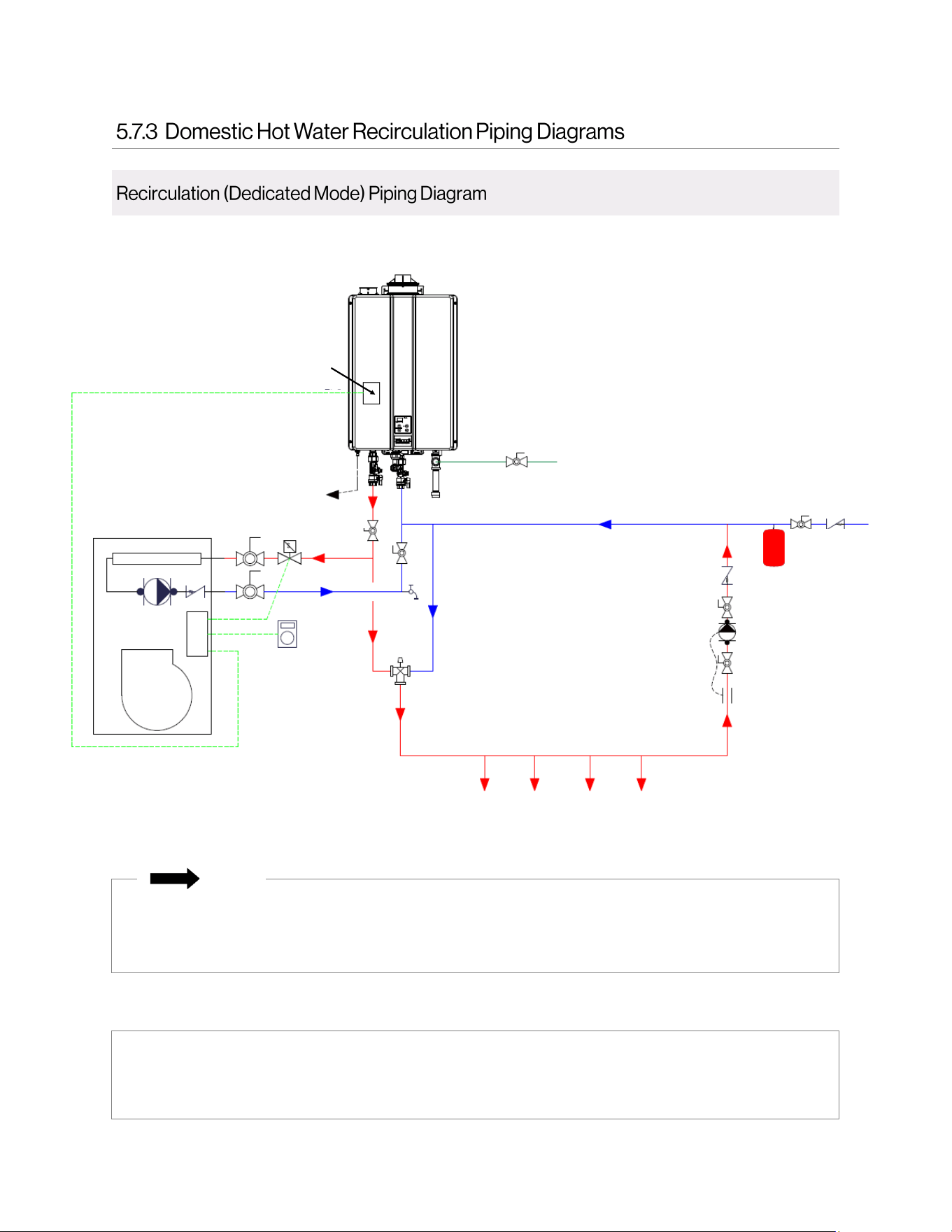
Domestic hot water recirculation circulates hot water through the plumbing system so that instant hot water is
available. Domestic hot water recirculation operates between calls for heat to ensure a balance of comfort for
HVAC heating and domestic hot water. If pairing a Rinnai Hydronic Air Handler with a tankless water heater for
domestic hot water recirculation capabilities, Rinnai recommends the following:
• Use an external recirculation pump controlled by a timer, aquastat, and/or an on-demand type control.
Do not use a Rinnai Tankless Water Heater equipped with recirculation capability
1
with the Rinnai
Hydronic Air Handler.
• Size the air handler based off of the maximum allowable temperature for the domestic hot water system.
Refer to section “5.7.3 Domestic Hot Water Recirculation Piping Diagrams” for domestic hot water recirculation
piping diagrams.
For more information on domestic hot water recirculation, refer to the tankless water heater installation and
operation manual.
1
Rinnai Tankless Water Heaters equipped with recirculation capability include the SE+ Series featuring ThermaCirc360™
models (Super High-Efficiency Plus RUR Models).
This section is referring to domestic hot water recirculation in the plumbing system and not the circulation
of hot water between the air handler and tankless water heater/boiler.
IMPORTANT
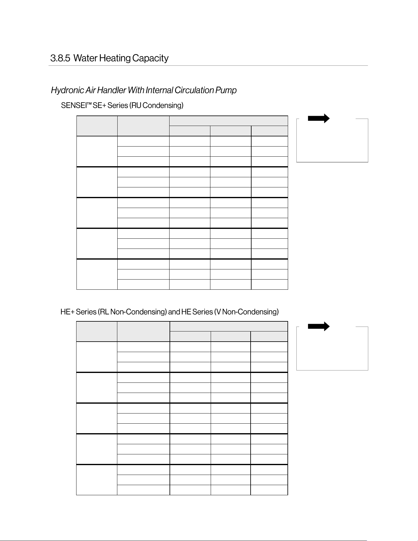
Hydronic Air Handler Installaon and Operaon Manual 13
Air Handler
Model
Entering Water
Temperature
Blower Speed (Btu/hr)
Low Medium High
AH083CP
120°F 21,000 23,000 24,000
140°F* 29,000 31,000* 34,000
160°F 37,000 40,000 43,000
AH084CP
120°F 22,000 25,000 27,000
140°F* 31,000 35,000* 38,000
160°F 40,000 44,000 47,000
AH125CP
120°F 31,000 33,000 34,000
140°F* 43,000 45,000* 47,000
160°F 55,000 58,000 61,000
AH166CP
120°F 40,000 41,000 42,000
140°F* 55,000 57,000 58,000*
160°F 70,000 73,000 75,000
AH206CP
120°F 40,000 41,000 41,000
140°F* 55,000 56,000 57,000*
160°F 70,000 71,000 72,000
•
•
Air Handler
Model
Entering Water
Temperature
Blower Speed (Btu/hr)
Low Medium High
AH083CP
120°F 21,000 23,000 25,000
140°F* 29,000 32,000* 34,000
160°F 38,000 41,000 45,000
AH084CP
120°F 23,000 26,000 28,000
140°F* 32,000 35,000* 39,000
160°F 41,000 45,000 49,000
AH125CP
120°F 32,000 34,000 35,000
140°F* 44,000 46,000* 49,000
160°F 57,000 60,000 63,000
AH166CP
120°F 42,000 43,000 44,000
140°F* 57,000 59,000 61,000*
160°F 74,000 76,000 79,000
AH206CP
120°F 41,000 42,000 43,000
140°F* 56,000 57,000 58,000*
160°F 73,000 74,000 76,000
* Bold text is default setting.
* Bold text is default setting.
NOTE
Tankless water
heaters must have a
minimum input rate
of 160,000 Btu/hr.
Values shown in following tables may vary depending on the static pressure of the duct system.
NOTE
Tankless water
heaters must have a
minimum input rate
of 160,000 Btu/hr.
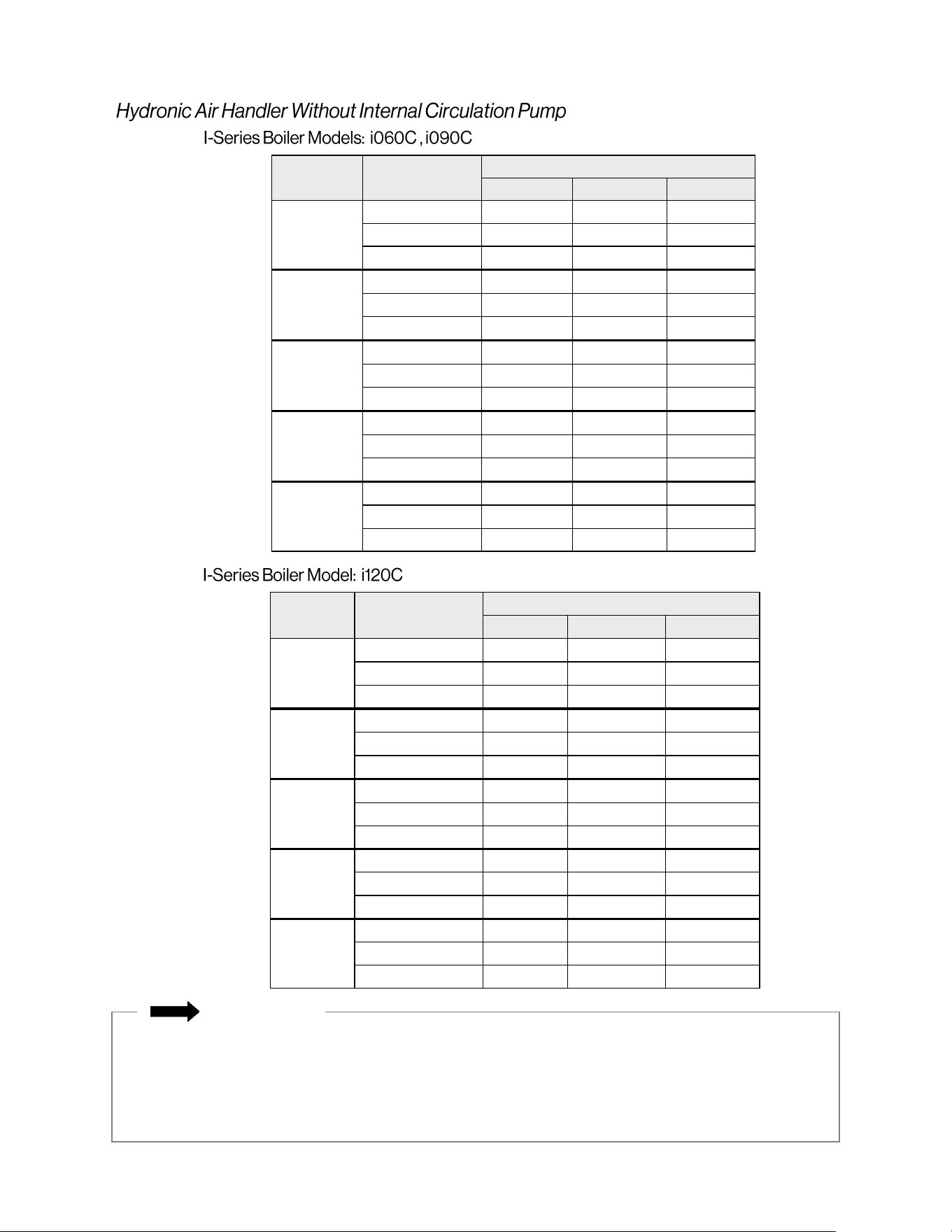
14 Hydronic Air Handler Installaon and Operaon Manual
Air Handler
Model
Entering Water
Temperature
Blower Speed (Btu/hr)
Low Medium High
AH083P
120°F 21,000 23,000 25,000
140°F* 29,000 32,000* 35,000
160°F 38,000 42,000 45,000
AH084P
120°F 23,000 25,000 27,000
140°F* 32,000 35,000* 38,000
160°F 41,000 46,000 50,000
AH125P
120°F 32,000 33,000 35,000
140°F* 44,000 47,000* 49,000
160°F 57,000 60,000 63,000
AH166P
120°F 41,000 42,000 44,000
140°F* 58,000 60,000 62,000*
160°F 75,000 78,000 80,000
AH206P
120°F 41,000 42,000 43,000
140°F* 58,000 60,000 61,000*
160°F 75,000 77,000 78,000
Air Handler
Model
Entering Water
Temperature
Blower Speed (Btu/hr)
Low Medium High
AH083P
120°F 21,000 23,000 25,000
140°F* 29,000 32,000* 35,000
160°F 38,000 41,000 45,000
AH084P
120°F 23,000 25,000 27,000
140°F* 32,000 35,000* 39,000
160°F 41,000 46,000 50,000
AH125P
120°F 32,000 34,000 35,000
140°F* 45,000 47,000* 50,000
160°F 58,000 61,000 64,000
AH166P
120°F 41,000 43,000 44,000
140°F* 58,000 60,000 62,000*
160°F 75,000 78,000 80,000
AH206P
120°F 41,000 42,000 43,000
140°F* 58,000 60,000 61,000*
160°F 76,000 77,000 79,000
•
IMPORTANT
• All capacities are based on 70°F entering air temperature.
• For entering air temperatures other than 70°F, use the following capacity correction factors:
(72°F x .982), (68°F x 1.02), (66°F x 1.04)
• Glycol correction factors: (10% X .98), (20% X .95), (30% X .92), (40% X .88)
• Refer to the “Approved Cleaners, Inhibitors and Antifreezes” section (in the Appendix of the “I-Series
Condensing Combi Boiler Installation and Operation Manual”) for a complete list of approved glycols.
* Bold text
is default
setting
•
* Bold text
is default
setting
Hydronic Air Handler Installaon and Operaon Manual 15
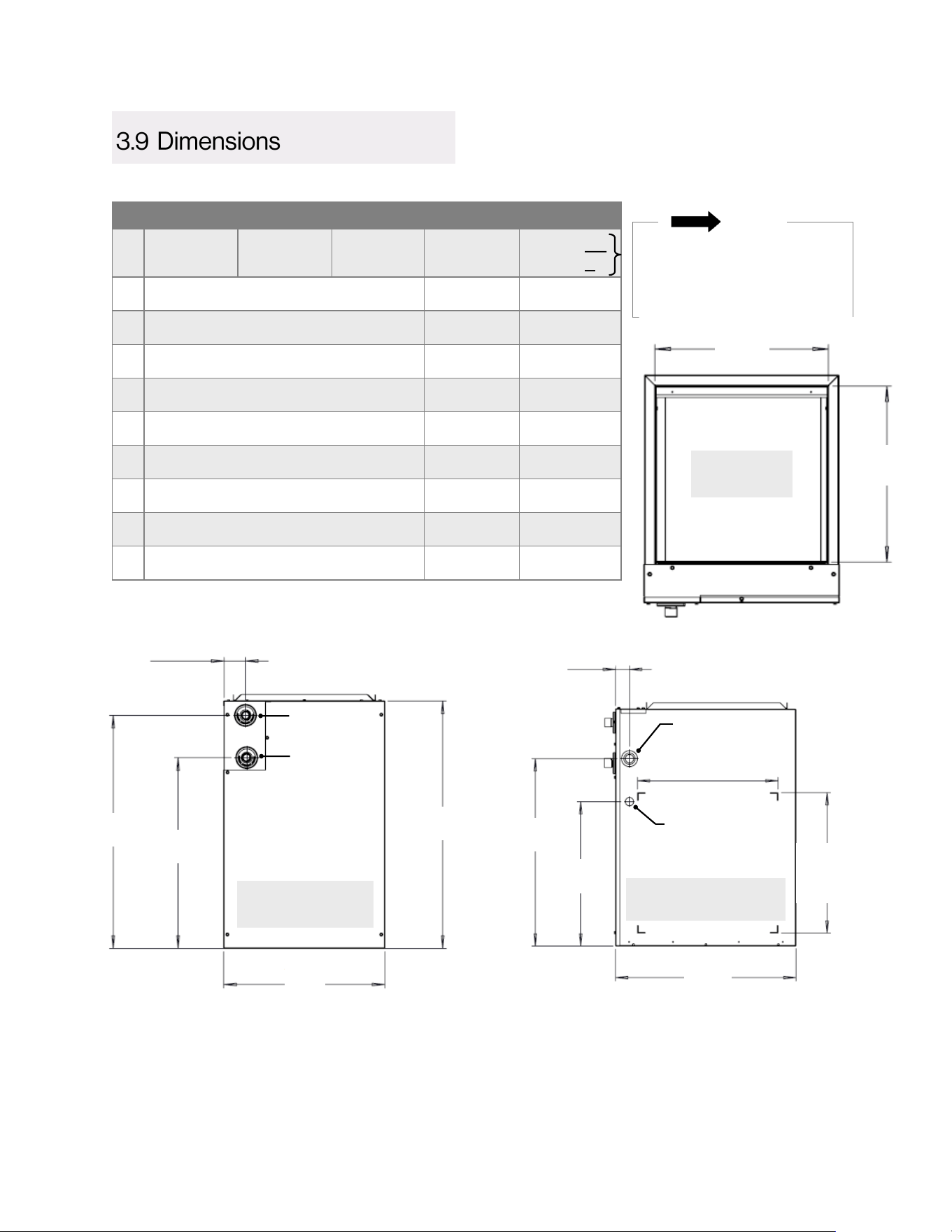
Measurements: in. (mm)
Hydronic Air Handler Models
• AH083CP
• AH083P
• AH084CP
• AH084P
• AH125CP
• AH125P
• AH166CP
• AH166P
• AH206CP
• AH206P
A
17.5 (445) 21.0 (533) 24.5 (622)
B
27.0 (686) 28.0 (711) 28.0 (711)
C
20.5 (521) 20.5 (521) 20.5 (521)
D
15.5 (394) 19.0 (483) 22.5 (572)
E
16.0 (406) 16.0 (406) 16.0 (406)
F
25.4 (645) 26.4 (671) 26.4 (671)
G
21.5 (546) 22.5 (572) 22.5 (572)
H
21.4 (544) 22.4 (569) 21.4 (543)
I
17.5 (445) 17.5 (445) 16.5 (419)
NOTE
CP = Models with Internal
Circulation Pump
P = Models without Internal
Circulation Pump
1
Line Voltage knockout is located at the specified height on the cabinet right side panel for models: AH083P/CP,
AH084P/CP, AH125P/CP, AH166P/CP
Line Voltage knockout is located at the specified height on the cabinet left side panel for models: AH206P/CP
2
Low Voltage/Thermostat knockouts are also available at same location on cabinet left side.
TOP
D
E
TOP
FRONT
Water In
Water Out
2.8
(71)
B
F
G
A
Line Voltage
1
(120V Supply)
Low Voltage/
Thermostat
(24V Supply)
2
1.6
(41)
RIGHT
16
(406)
RIGHT
I
(406)
16
H
C
16 Hydronic Air Handler Installaon and Operaon Manual
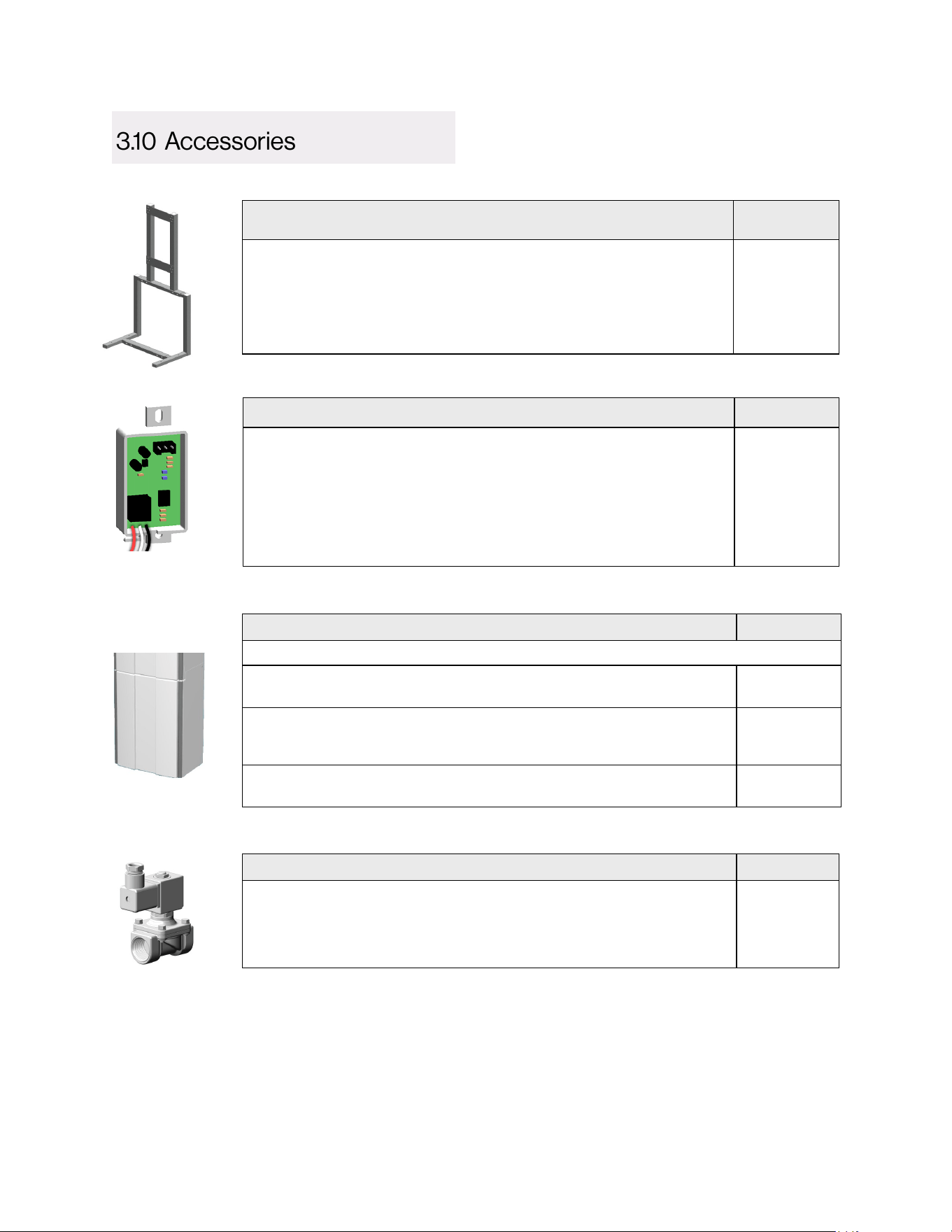
Universal Air Handler Rack Assembly Part #
Universal rack assembly that mounts to the Rinnai Tankless Water
Heater or Boiler for simple installation with the hydronic air handler.
Works with all Rinnai AH Series Hydronic Air Handler models.
Includes hardware for mounting the tankless water heater or boiler to
the air handler rack assembly, and hardware for assembling the rack.
AHRACK-1
Domestic Priority Switch Part #
Normally Closed (NC) switch that connects to the PC Board in the
Rinnai tankless water heater or boiler.
Allows the tankless water heater or boiler to give priority to domestic
hot water by shutting off the air handler when necessary. When used
with a hydronic air handler, the switch gives priority to domestic hot
water. When domestic hot water demand exceeds a certain point, the
air handler will turn off to ensure the demand is met.
REU-OPU3
Pipe Cover Enclosure Part #
Encloses the piping below the tankless water heater or boiler for aesthetic purposes.
• Pipe cover for HE+ Series (RL Non-Condensing) Tankless Water
Heater Models
PCD03-SM2
• Pipe cover for SENSEI™ SE+ Series (RU Condensing) Tankless
Water Heater Models and I-Series (Condensing) Combi Boiler
Models
PCD07-SM
• Pipe cover for HE Series (V Non-Condensing) Tankless Water
Heater Models
PCD03-EWV
Product images are for illustrative purposes only.
24V NC Brass Solenoid Valve (3/4” NPT ) Part #
Optional accessory for use in domestic hot water recirculation
applications. The solenoid valve installs in line with the air handler
pump and is wired to the 24V Valve terminal on the air handler control
board. 1.12A Max Current Draw.
607000018
Hydronic Air Handler Installaon and Operaon Manual 17
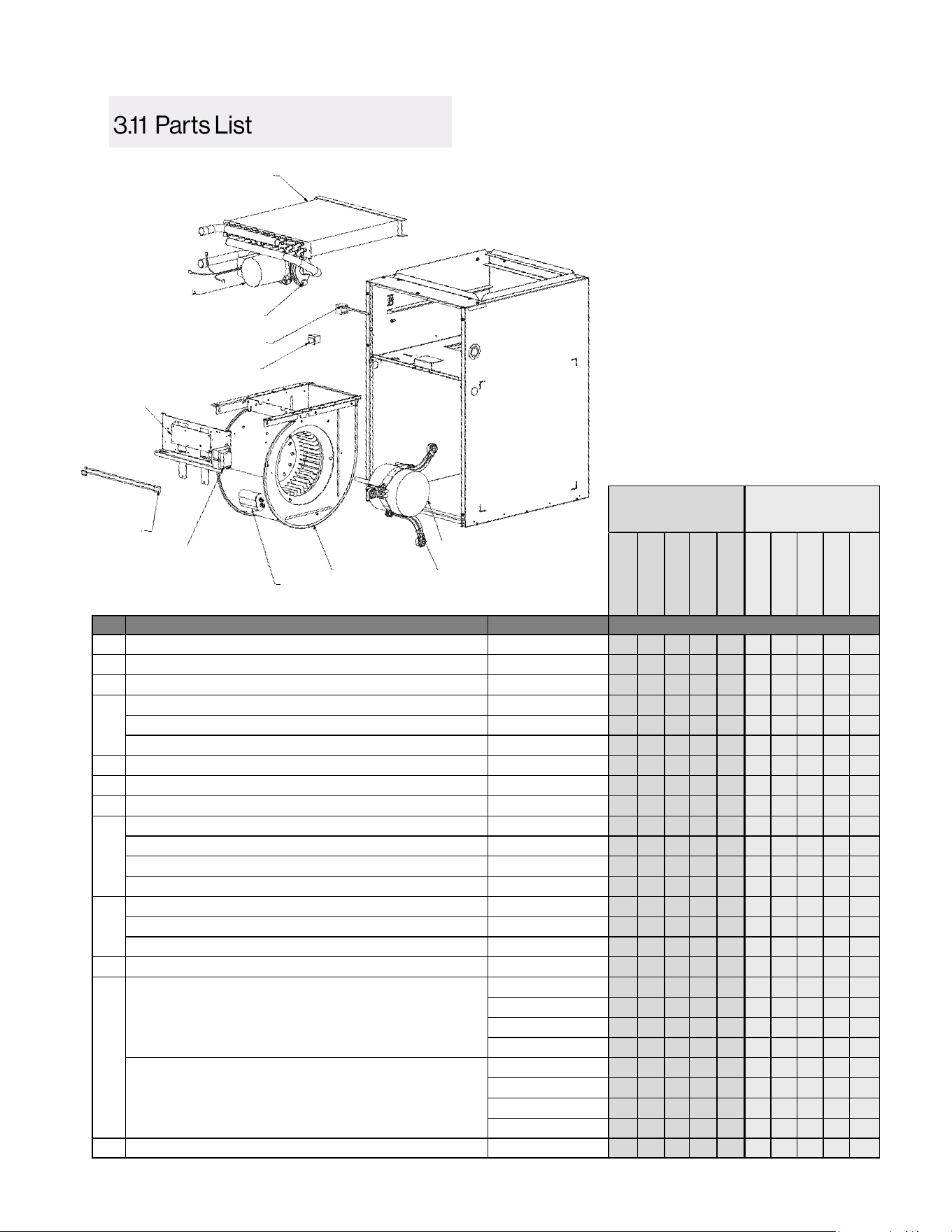
❽
❿
❹
❾
❷
❻
❸
⓬
❼
❺
❶
⓫
Models With
Internal
Circulation Pump
Models Without
Internal
Circulation Pump
AH083CP
AH084CP
AH125CP
AH166CP
AH206CP
AH083P
AH084P
AH125P
AH166P
AH206P
# Description Rinnai Part # Quantity
1 Pump - With Internal Check Valve, 120 Volts 607000033 1 1 1 1 1 0 0 0 0 0
2 Transformer - 120 Volt, 60 Hz. 605000044 1 1 1 1 1 1 1 1 1 1
3 Multi-Function Control Board 605000033 1 1 1 1 1 1 1 1 1 1
4
7.5 MFD Capacitor 605000034 1 1 0 0 0 1 1 0 0 0
10 MFD Capacitor 605000035 0 0 1 0 0 0 0 1 0 0
12.5 MFD Capacitor 605000036 0 0 0 1 1 0 0 0 1 1
5 6 Pin Wire Harness 605000037 1 1 1 1 1 1 1 1 1 1
6 Rinnai Wiring Harness 605000038 1 1 1 1 1 1 1 1 1 1
7 Door Switch 605000039 1 1 1 1 1 1 1 1 1 1
8
Blower Motor 1/3 HP, 120 Volt, 60 Hz. 605000040 1 1 0 0 0 1 1 0 0 0
Blower Motor 1/2 HP, 120 Volt, 60 Hz. 605000041 0 0 1 0 0 0 0 1 0 0
Blower Motor 3/4 HP, 120 Volt, 60 Hz. 605000042 0 0 0 1 0 0 0 0 1 0
Blower Motor 3/4 HP, 120 Volt, 60 Hz. 605000043 0 0 0 0 1 0 0 0 0 1
9
9" x 6" Blower Housing Assembly 608000029 1 1 0 0 0 1 1 0 0 0
10" x 8" Blower Housing Assembly 608000030 0 0 1 1 0 0 0 1 1 0
10" x 10" Blower Housing Assembly 608000031 0 0 0 0 1 0 0 0 0 1
10 Motor Mount Assembly (includes ring and legs) 609000063 1 1 1 1 1 1 1 1 1 1
11
Hot Water Replacement Coil With Pump and
Valve Assembly
607000022 1 0 0 0 0 0 0 0 0 0
607000023 0 1 1 0 0 0 0 0 0 0
607000025 0 0 0 1 0 0 0 0 0 0
607000026 0 0 0 0 1 0 0 0 0 0
Hot Water Replacement Coil With No Pump and
Valve Assembly
607000027 0 0 0 0 0 1 0 0 0 0
607000028 0 0 0 0 0 0 1 1 0 0
607000030 0 0 0 0 0 0 0 0 1 0
607000031 0 0 0 0 0 0 0 0 0 1
12 3/4" Sweat Flange Kit 607000032 1 1 1 1 1 0 0 0 0 0
18 Hydronic Air Handler Installaon and Operaon Manual
Gather the required tools and parts before
starting installation. Read and follow the
instructions provided with any tools listed below.
• 1/4 in. nut driver
• Level
• Screwdriver
• Adjustable wrench
• Tape Measure
• Hammer
• AHRI Approved Duct Sealant
• UL listed wire nuts
When choosing an installation location, you must
ensure proper clearances will be met; the
installation environment; water quality; and the
need for freeze protection.
Carefully unpack the air handler. If the unit is
damaged, contact your local dealer/distributor.
Do not attempt to use the air handler if it
appears damaged.
The blower section is factory assembled and all
components are performance tested.
The air handler consists of a blower assembly
and controls in an insulated, galvanized steel
factory finished enclosure. Knockouts are
provided for electrical wiring entrance.
Inspect the following:
• Check the air handler rating plate to confirm
specifications are as ordered.
• Upon receipt of air handler, thoroughly
inspect the system for possible shipping
damage. If the carton appears damaged,
closely examine the air handler inside the
carton.
• If the air handler appears to be damaged or
is torn loose from its anchorage, the air
handler must be immediately examined by
the receiving party before removal. If
damage is found, the receiving party must
sign the driver’s delivery receipt noting all
damage (i.e. carton damage and/or product
damage), as well as contact the last carrier
immediately, preferably in writing,
requesting inspection by the carrier’s agent.
• To prevent loss or damage, leave all parts
in original packages until installation.
Contaminant Maximum Level
Total Hardness Up to 200 mg/L
Aluminum * Up to 0.2 mg/L
Chlorides * Up to 250 mg/L
Copper * Up to 1.0 mg/L
Dissolved Carbon
Dioxide (CO2)
Up to 15.0 mg/L
Iron * Up to 0.3 mg/L
Manganese * Up to 0.05 mg/L
pH * 6.5 to 8.5
TDS (Total Dissolved
Solids) *
Up to 500 mg/L
Zinc * Up to 5 mg/L
* Source: Part 143 National Secondary
Drinking Water Regulations
This section provides information on the
importance of water quality to the air handler. The
information is intended to serve as general
guidelines only and is not a complete list of water
quality guidelines.
Consideration of care for the air handler should
include evaluation of water quality.
• The water must be potable, free of corrosive
chemicals, sand, dirt, or other contaminants.
• It is up to the installer to ensure the water
does not contain corrosive chemicals or
elements that can affect or damage the boiler
or tankless water heater.
• Water that contains chemicals exceeding the
levels below can damage the boiler or
tankless water heater.
Hydronic Air Handler Installaon and Operaon Manual 19
Replacement of components due to water
quality damage is not covered by the warranty.
• Unsuitable heating system water can cause
the formation of scale or sludge, which
affects system efficiency. It can also cause
corrosion and reduce life of the heat
exchanger.
• Never use water that has been treated by a
reverse osmosis, deionized, or distilled
water to soften the water to fill the heating
system.
• Louvers or return air grilles are field-supplied.
Local codes may limit application of systems
without a ducted return to single-story
buildings.
• For a unit installed in a closet with a louvered
return opening, the minimum open area for
the louvers are:
Non-Ducted Return Closet Installation
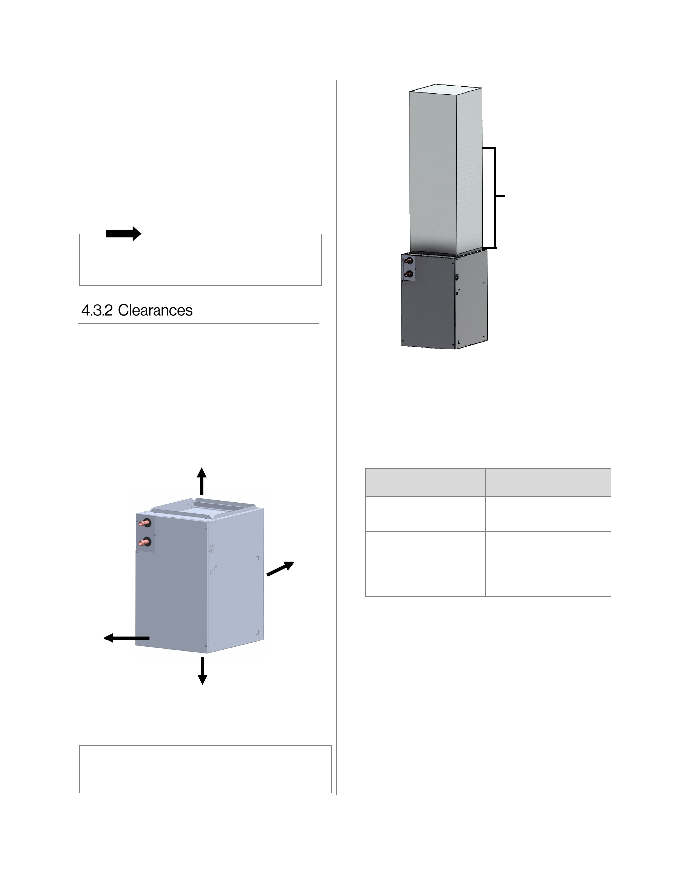
• Clearances to combustible material is 0 in.
from unit casing, and 0 in. to plenum and
duct for first 36 in. (914 mm) and throughout
the remaining ductwork system.
• Clearance for servicing is 24 in. (610 mm) in
front of air handler.
FRONT
0 in.
SIDE
0 in.
BACK
0 in.
TOP
0 in.
BOTTOM
0 in.
SERVICING
24 in.
(610 mm)
Images are not to scale and are for illustration purposes
only. Images do not show a complete system with
plenums, duct pipes, etc.
Clearances to
combustible
material is 0 in. to
plenum and duct for
first 36 in. (914 mm)
and throughout the
remaining ductwork
system.
IMPORTANT
• If the free area is not known, assume a 25%
free area for wood or a 75% free area for metal
louvers or grilles. Using the louver dimensions
and the 25% or 75% assumption, determine if
the louver open area meets the minimum open
area listed above.
• If the return air plenum is used, the return air
grille should be immediately in front of the
opening in the plenum to allow for the free flow
of return air.
• When not installed in front of the opening, there
must be adequate clearance around the air
handler to allow for the free flow of return air.
Air Handler Models Minimum Opening Area
• AH083P/AH083CP
• AH084P/AH084CP
320 square inches
(0.206 square meters)
• AH125P/AH125CP
360 square inches
(0.23 square meters)
• AH166P/AH166CP
• AH206P/AH206CP
450 square inches
(0.29 square meters)
20 Hydronic Air Handler Installaon and Operaon Manual
• This air handler is certified for installation in
residential and light commercial applications
and approved for the following configurations:
− Vertical: Upflow with bottom or side (left or
right side) return
− Horizontal (upflow with bottom return)
• All models are designed for indoor installation
only.
• These instructions are intended as a general
guide only and do not supersede national or
local codes. Compliance with all local, state, or
national codes pertaining to this type of
equipment should be determined prior to
installation.
• Read this entire manual, as well as the
instructions supplied in separate equipment,
before starting installation.
• It is recommended that a trained and qualified
professional who has attended a Rinnai
installation training class complete your
installation.
• Installation of the blower section, field wiring,
warm air ducts, etc. must conform to the
requirements of the National Electrical Code,
ANSI/NFPA No. 70 (latest edition) in the United
States, and any state laws, and local
ordinances (including plumbing or wastewater
codes). Local authorities having jurisdiction
should be consulted before installation begins.
Such applicable regulations or requirements
take precedence over the general instructions
in this manual.
• Install the conditioned air plenum, ducts and air
filters (not provided) in accordance with NFPA
90B Standard for the Installation of Warm Air
Heating and Air-Conditioning Systems (latest
edition). The blower section is provided with
flanges for the connection of the plenum and
ducts. Air filters must be listed as Class 2
furnace air filters. The blower section is shipped
from the factory completely assembled.
• For ease in installation, it is best to make any
necessary coil configuration changes before
connecting the air handler to the coil.
• Do not remove the cabinet knockouts until it
has been determined which knockouts need to
be removed for the installation.
• Select the final installation position that best
suits the site conditions. Consider required
clearances, space, and routing requirements for
refrigerant line, condensate disposal, filters,
ductwork, wiring, and accessibility for service.
Refer to the rating plate on the blower section
for specific information.
• When the unit is installed in a humid space
and used in cooling applications, excessive
sweating may occur on outside of unit. To
prevent excessive sweating wrap unit with
1 in. (25 mm) fiberglass insulation. All
openings should be sealed to prevent air
leakage that could cause condensate to
form inside the cabinet.
• If installed in an unconditioned space,
sealant should be applied around the
electrical wires, refrigerant tubing, and
condensate lines where they enter the
cabinet.
• Electrical wires should be sealed on the
inside where they exit the conduit opening.
Sealant is required to prevent air leakage
and condensate from forming inside the
blower, control box, and on the electrical
controls.
• The air handler and its complementing
cooling coil must be installed in such a way
as to allow free access to the air handler/
control compartment.
• The air handler and its complementing
cooling coil must be installed with a 3/4 in.
(19 mm) drop in the horizontal position
towards the drain pan to ensure proper
condensate drainage. The air handler and
coil should also be tilted 1/2 in. (13 mm)
from back to front toward the drain line.
The Clean Air Act of 1990 bans the
intentional venting of refrigerant (CFC’s and
HFC’s) as of July 1, 1992. Approved
methods of reclaiming must be followed.
Fines and/or incarceration may be levied for
non-compliance.
IMPORTANT
• Do not install this air handler if it is
damaged.
• Do not install this air handler if any part
or all of the unit has been under water.
Explosion Hazard:
• Keep flammable materials and vapors,
such as gasoline, away from this unit.
• Failure to follow these instructions can
result in death, explosion or fire.
WARNING
Hydronic Air Handler Installaon and Operaon Manual 21
• Install ductwork in accordance with NFPA
90B and any local codes.
• Install the conditioned air plenum, ducts
and air filters (not provided) in accordance
with NFPA 90B Standard for the
installation of Warm Air Heating and Air-
Conditioning Systems (latest edition).
• Isolation connectors (if utilized) must be
nonflammable.
• Duct connections for the air handler with
hot water heat must allow room for water
piping connections to be made in the
upflow configuration.
• A return air duct system is recommended.
If the unit is installed in a confined space or
closet, a return connection must be run, full
size, to a location outside the closet.
• The air handler is provided with flanges for
the connection of the plenum and ducts.
• Air filters must be listed as Class 2 furnace
air filters.
• Supply and return ductwork must be
adequately sized to meet the system’s air
requirements and static pressure
capabilities. Ductwork should be insulated
with a minimum of 1 in. (25 mm) thick
insulation with a vapor barrier in
conditioned areas or 2 in. (51 mm)
minimum in unconditioned areas.
• Supply plenum should be the same size as
the flanged opening provided around the
blower outlet and should extend ideally at
least 3 ft. (1 m) from the air handler before
turning or branching off plenum into duct
runs. The plenum forms an extension of
the blower housing and minimizes air
expansion losses from the blower.
• All wiring must conform to local and national
electrical codes. Improper wiring or
installation may damage thermostat.
• Air Conditioner Model: The Standard Model
A/C thermostat may be wired with or without
connecting a common wire between the
indoor equipment and the thermostat.
However, it is recommended to use a
common wire whenever possible to prevent
power stealing by the thermostat.
• Heat Pump Model: The standard model
heat pump thermostat is not "power
stealing" and must have both ‘R’ and ‘C’
wires connected to operate properly. The
thermostat should have an indicator for
when auxiliary heat is in use.
• The thermostat should NOT be mounted:
− Close to a window, on an outside wall,
or next to a door leading to the outside
− Exposed to direct light and heat from a
lamp, sun, fireplace, or other heat-
radiating objects which may cause a
false reading
− Close to or in direct airflow from supply
registers and return-air grilles
− In areas with poor air circulation, such
as behind a door or in an alcove
Before installing or servicing the air handler,
turn off power to unit. There may be more
than one disconnect switch. Electrical shock
can cause personal injury or death.
WARNING
22 Hydronic Air Handler Installaon and Operaon Manual
• Use copper conductors only.
• All field wiring must be done in accordance
with National Electrical Code, applicable
requirements of UL and local codes, where
applicable.
• Electrical wiring, disconnect means and
over-current protection are to be supplied by
the installer. Refer to the air handler rating
plate for maximum over-current protection,
minimum circuit ampacity, as well as
operating voltage.
• The power supply must be sized and
protected according to the specifications
supplied on the product.
• This air handler is factory-configured for 120
Volts, single phase, 60 Hz.
• Prior to making any electrical connections,
ensure that supply voltage, frequency, and
phase are as specified on unit rating plate.
• Check to ensure that the existing electrical
service is adequate to handle the additional
load imposed by the Hydronic Furnace.
Refer to unit wiring diagram for proper
electrical connections.
• All electrical connections MUST comply with
NEC and any other local codes or
ordinances having jurisdiction. USE
COPPER WIRE ONLY. Provide separate
branch electric circuit with field supplied
disconnect switch.
• Location of disconnect switch to be in clear
site, accessible and in close proximity to the
unit.
• Correct polarity MUST be maintained for
120 V wiring. If polarity is incorrect unit will
NOT operate.
Electrical Shock:
• Disconnect power before servicing.
• Replace all parts and panels before
operating.
• Electrically ground the air handler.
• Connect ground wire to ground terminal
marked “GRD”.
• Failure to do so can result in death or
electrical shock.
• Before installing or servicing the air
handler, turn off power to unit. There may
be more than one disconnect switch.
• If a disconnect switch is to be mounted on
the unit, select a location where a drill or
fastener will not contact electrical or
hydronic components.
• Electrical shock can cause personal injury
or death.
WARNING
Explosion Hazard:
• Keep flammable materials and vapors,
such as gasoline, away from this unit.
• Failure to follow these instructions can
result in death, explosion or fire.
WARNING
Line-Voltage Connections:
• U.S. Installations: Make all electrical
connections in accordance with National
Electrical Code (NEC) ANSI/NFPA 70 and all
local codes or ordinances having jurisdiction.
• Canadian Installations: Make all electrical
connections in accordance with Canadian
Electrical Code CSA C22.1 and all authorities
having jurisdiction.
• Check all factory wiring per unit wiring
diagram and inspect factory wiring
connections to be sure none were loosened in
transit.
Hydronic Air Handler Installaon and Operaon Manual 23
Thermal Expansion of Piping
In all hydronic systems, piping undergoes
temperature swings as the system operates.
This causes changes in the length of the piping
due to thermal expansion.
If the piping is rigidly mounted, this expansion
can cause annoying popping or squeaking
sounds and in extreme cases, the piping can
even buckle.
To counter expansion movement, design piping
circuits with sufficient elbows, tees or
expansion loops (only used in large systems)
or piping supports that allow the tubing to
expand and contract freely.
Another alternative is to install an expansion
compensator fitting capable of absorbing the
movement.
Hydraulic Resistance of Fittings, Valves,
and Other Devices
Before the total hydraulic resistance of a piping
circuit can be found, the individual hydraulic
resistances of all fittings, valves, or other such
components must be determined. One
approach is to consider each fitting, valve, or
other device as an equivalent length of copper
tube of the same pipe size.
By using the equivalent length of piping for all
components in the circuit, the circuit can be
treated as if it were a single piece of pipe
having a length equal to the sum of the actual
pipe length, the total equivalent lengths of all
fittings, valves, or other devices.
Pipe Sizing Considerations
When selecting a pipe size for a given flow
rate, the resulting average flow velocity
should be between 2 ft. (0.61 m) and 4 ft.
(1.22 m) per second.
At water flow velocities of approximately 2
ft. (0.61 m) per second, flowing water will
carry air bubbles along a vertical pipe.
Average flow velocities of 2 ft. (0.61 m) per
second or higher can draw along air
bubbles in a downward flow. At the above
stated velocities air bubbles shall be routed
to an air separator where they can be
collected and discharged from the system.
Average flow velocities higher than 4 ft.
(1.22 m) per second could cause flow noise
and premature wear of piping and fittings
and should be avoided.
Expansion Tanks
All liquids used in hydronic heating systems
expand when heated. For all practical
purposes, liquids are incompressible. Any
container completely filled with a liquid and
sealed from the atmosphere will experience
a rapid increase in pressure as the liquid is
heated. To prevent this from occurring, all
hydronic systems MUST be equipped with
an expansion tank. See the following
sections for the expansion tank plumbing
location:
• 5.7.1 Rinnai Tankless Water Heater
and Air Handler Piping Diagram
• 5.7.2 Rinnai I-Series Boiler and Air
Handler Piping Diagram
Use only approved piping and fitting materials. If
used in an open loop system with domestic hot
water, potable, lead-free piping must be used.
IMPORTANT
Solder joints on domestic water lines must be
made with NO-LEAD SOLDER.
WARNING
24 Hydronic Air Handler Installaon and Operaon Manual
Read section “4. Installation Preparation”
before starting installation steps.
IMPORTANT
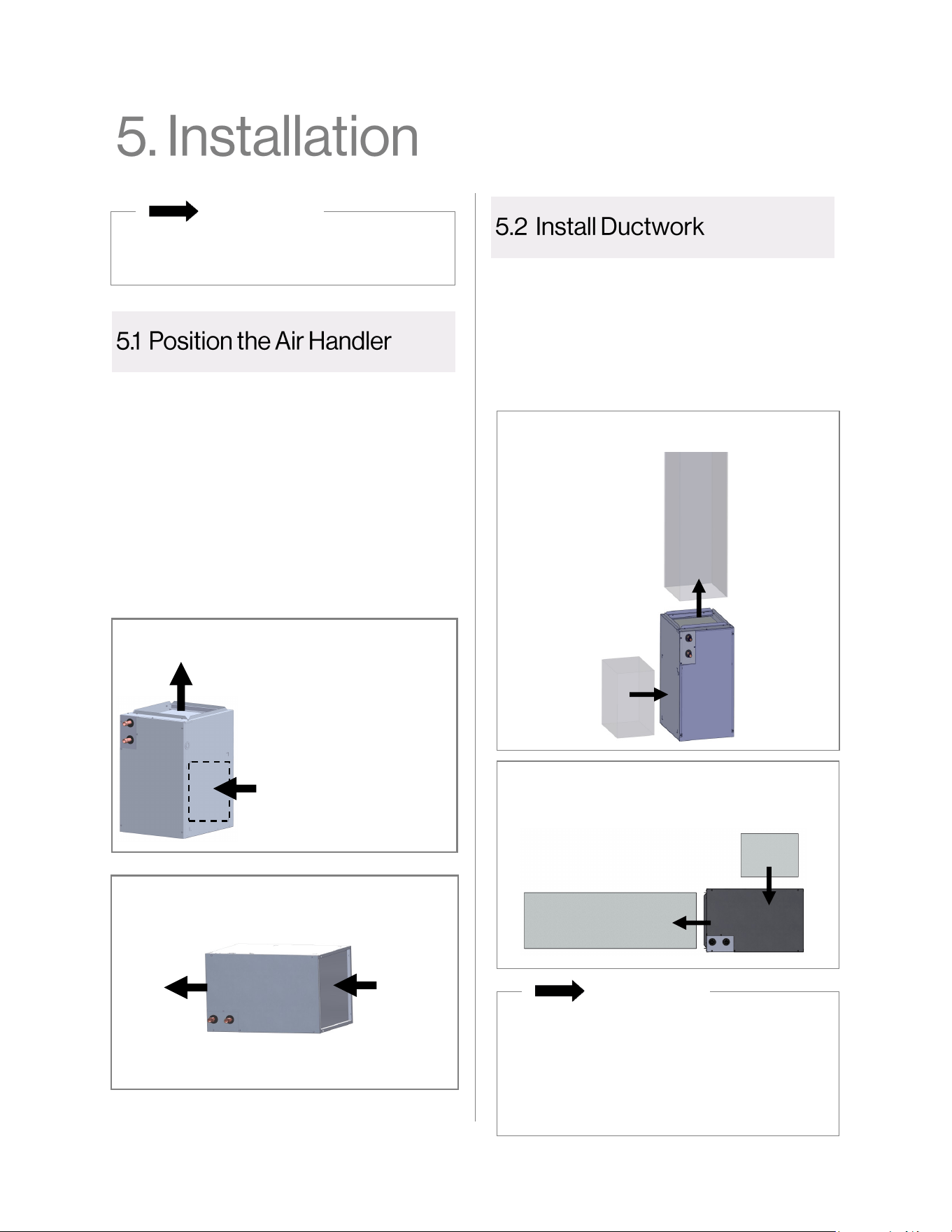
1. Place the air handler in the desired location
and configuration. Approved configurations:
Refer to the previous section (section “4.
Installation Preparation”) for more information
on location and configuration requirements.
1. Connect the supply air duct to the flange on
top of the blower section of the air handler.
Refer to section “4.5 Ductwork Requirements”
for complete ductwork installation
requirements.
• A return air duct system is recommended.
If the unit is installed in a confined space
or closet, a return connection must be
run, full size, to a location outside the
closet.
• The isolation connector (if used) must be
nonflammable.
IMPORTANT
RETURN
SUPPLY
Example Vertical Installation
Example Horizontal Installation
SUPPLY
RETURN
• Vertical: Upflow with bottom or side
(left or right side) return
• Horizontal: Upflow with bottom return
SUPPLY (Upflow)
RETURN
Air flows in through bottom or
side (left or right side)
Vertical (upflow with bottom or side return)
Air flows out through top
Horizontal (Upflow with bottom return)
RETURN
Air flows in
through
“bottom
duct return”
SUPPLY
Air flows
out
through
“top”
Hydronic Air Handler Installaon and Operaon Manual 25
Refer to section “4.7 Electrical Requirements”
for complete electrical requirements.
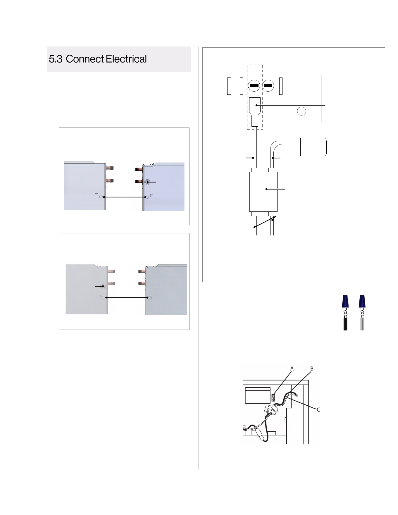
1. Disconnect all power supplies.
2. Remove the air handler access panel by
removing the 4 screws that secure the
panel.
3. Route the 120V power supply cable (field-
supplied) through the power supply
connection knockout hole and connect to
the air handler PC Board.
4. Route the 24V thermostat cable (field-
supplied) through the thermostat
connection knockout hole and connect to
the air handler PC Board.
5. If installing the Domestic Priority Switch
(recommended optional accessory
purchased separately), connect it to the air
handler PC Board (see following image).
8. (Optional) If you would like to change the fan
motor speed, follow the steps in section “8.2
Change Fan Motor Speed.”
9. Replace the air handler access panel.
6. Using UL listed wire nuts, connect the
field-supplied wires to the air handler
(black to black and white to white).
Note: Electrical cables go through the knockout
holes on the left or right side of the cabinet. See
the images below for specific locations.
Models: AH083P/CP, AH084P/CP,
AH125P/CP, AH166P/CP
Left Side
Right Side
Power
Supply
Knockout
Thermostat
Connection
Knockout
Model AH206P/CP
Left Side
Right Side
Power
Supply
Knockout
Thermostat
Connection
Knockout
7. Connect the following:
A. Connect ground wire to ground terminal marked “GND”
B. Connect black to black
C. Connect yellow to yellow, or white to white
Air Handler PCB
W2 W1 W G G
Connect
Push Connector
to “W” Wiring
on Thermostat
To
Thermostat
To Air
Handler
PCB
To Domestic Priority Switch
Connect to White and Black Wires (Normally Closed
Wiring Configuration) on Rinnai Domestic Priority Switch
IMPORTANT: If the Domestic Priority Switch is not used in
the installation, remove the wiring harness from the PCB. The
thermostat “W” wire should be directly wired to the PC Board.
Connect Spade
Connector to
“W” Terminal on
Air Handler PCB
Push Connector
to Thermostat
Connections to the Air Handler PC Board
Push-in Wire
Connector Assembly
26 Hydronic Air Handler Installaon and Operaon Manual
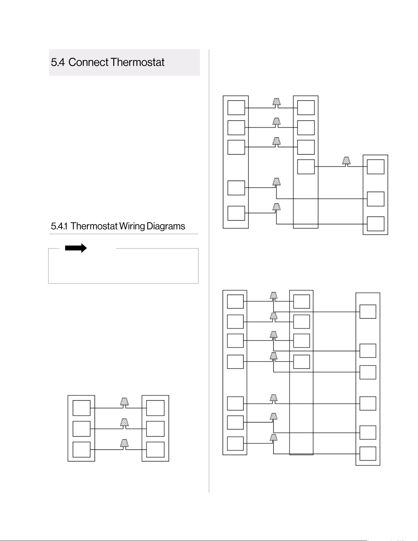
1. Mount the thermostat approximately 5 ft.
(1.5 m) from the floor and close to, or in, a
frequently used room, preferably on an
inside partitioning wall or a section of wall
without pipes or duct work.
2. Connect the thermostat to the air handler.
Follow the wiring diagrams in the next
section: “5.4.1 Thermostat Wiring
Diagrams.”
Heat Pump Application with Hot Water Heat
3-Speed PSC Motor
Maximum allowable current draw from power-
stealing thermostats or other accessories is 18
mA. Exceeding this value may cause the air
handler control board to operate abnormally.
Hot Water Heat Only Application
Cooling Application with Hot Water Heat
R R
G
W
G
W
RED
Thermostat Air Handler
GRN
WHT
NOTE: Connect common (C) wire only if required. See
thermostat installation instructions for more information.
Refer to section “4.6 Thermostat Requirements”
for complete thermostat installation
requirements.
For thermostat wiring with the Domestic Priority
Switch, refer to section “5.6.6 Air Handler and
Thermostat Wiring.”
NOTE
Thermostat
Air Handler
Y2
Y1
O
W
C
R
W
C
G
R
YEL/
BLU
YEL
ORG
WHT
BLU
GRN
RED
Y2
Y1
O
W
C
G
R
Condensing
Unit
R
R
G
W
G
W1
C
C
Y1
Y1
Y2
Y2
RED
GRN
WHT
YEL
YEL/
BLU
BLU
Thermostat
Air Handler
Condensing
Unit
Hydronic Air Handler Installaon and Operaon Manual 27
Install the Rinnai Tankless Water Heater or
Boiler by following the Installation and Operation
Manual supplied with the unit.
• For Tankless Water Heaters -
SENSEI™ SE+ Series (RU Condensing) Models:
Refer to the next section: “5.6.1 Option A: Installation
Instructions for SENSEI™ SE+ Series (RU
Condensing) Tankless Water Heaters”
• For Tankless Water Heaters -
HE+ Series (RL Non-Condensing) and
HE Series (V Non-Condensing) Models: Refer to
section: “5.6.2 Option B: Installation Instructions for
HE+ Series (RL Non-Condensing) and HE Series (V
Non-Condensing) Tankless Water Heaters”
• For I-Series Boiler Models: Refer to section “5.6.3
Option C: Installation Instructions for I-Series Combi
Boilers”
IMPORTANT
IMPORTANT
The Domestic Priority Switch (part # REU-
OPU3) is an optional accessory (purchased
separately) recommended for use with the
hydronic air handler.
The Domestic Priority Switch allows the tankless
water heater or boiler to give priority to domestic
hot water by shutting off the air handler when
necessary. When used with a hydronic air
handler, the switch gives priority to domestic hot
water. When domestic hot water demand
exceeds a certain point, the air handler will turn
off to ensure the demand is met.
The Domestic Priority Switch is a Normally
Closed (NC) switch that connects to the PC
Board in the Rinnai tankless water heater or
boiler.
To install the Domestic Priority Switch, open the
contents of the Domestic Priority Switch shipping
package and follow the remaining instructions in
this section.
You Will Need:
• Parts inside switch shipping package
• Philips head screwdriver (for removal of
water heater or boiler front cover)
• Double-sided tape (for boiler models)
If you are not installing the Domestic Priority
Switch:
• Skip this section and proceed to section
“5.7 Connect Water Lines.”
• Ensure not to short out the harness
connectors that would normally be used
with the Domestic Priority Switch.
Ensure the power supply to the water heater and
hydronic air handler is disconnected before starting
installation. Removing the front cover will expose live
mains voltage connections.
WARNING
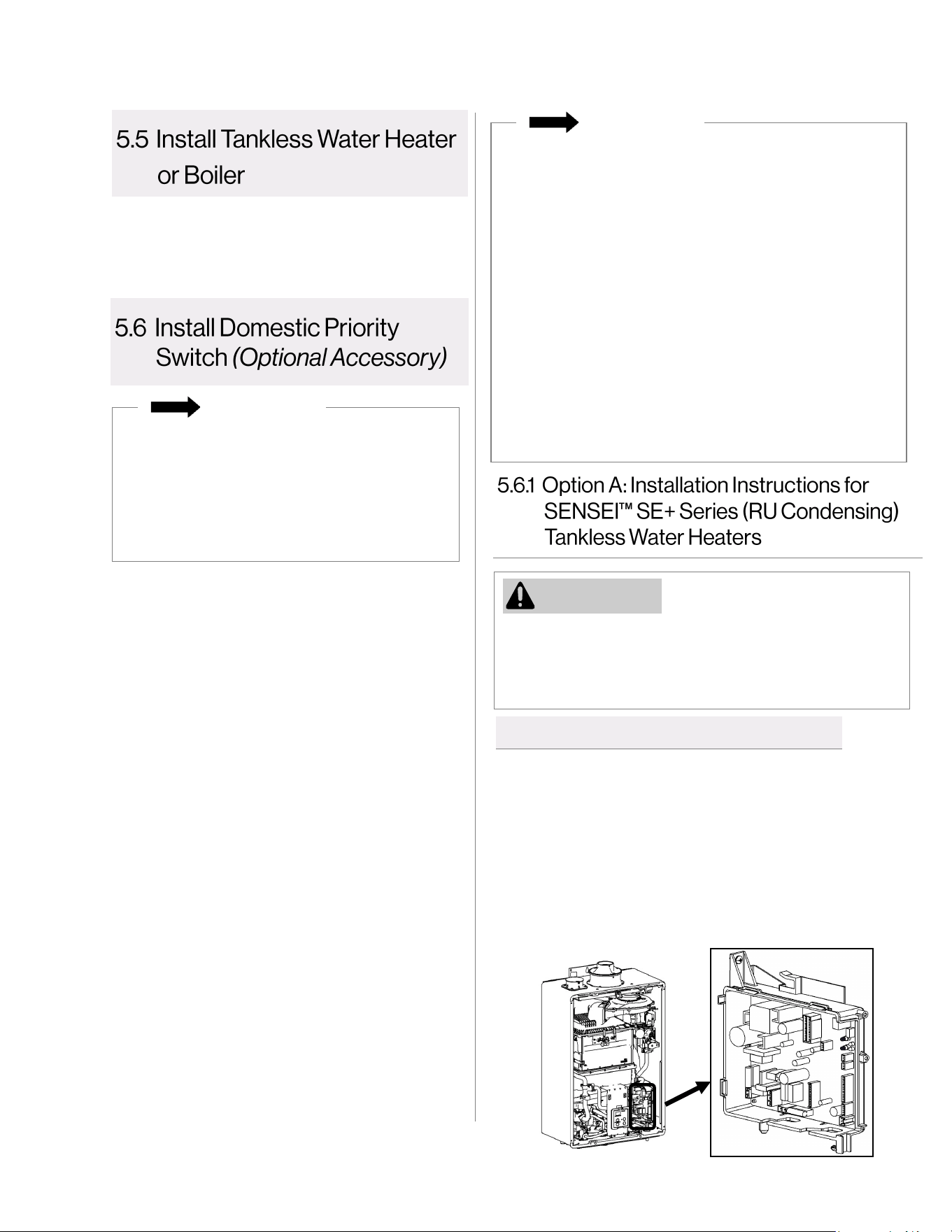
1. Power off the water heater by unplugging the power
cord or turning off the circuit breaker. The controller
on the water heater does not control the electrical
power.
2. Remove the front panel of the water heater by
removing the four screws that secure the panel in
place.
3. Locate the PC Board in the bottom, right corner of
the water heater.
PC Board
5.6.1.1 Install Switch Circuit Board
28 Hydronic Air Handler Installaon and Operaon Manual
5. For internal units, flip the switch circuit board to where the circuit board side will be facing the inside
of the unit.
4. Connect one end of the accessory cable to the accessory port on the PC Board. Connect the other
end of the cable to the switch circuit board accessory port.
PC Board
accessory
port
Switch circuit
board
accessory port
Accessory cable
Internal (Indoor) Units
External (Outdoor) Units
6. Install the switch circuit board to the controller bracket using the hooks at the top of the controller
bracket.
Hydronic Air Handler Installaon and Operaon Manual 29
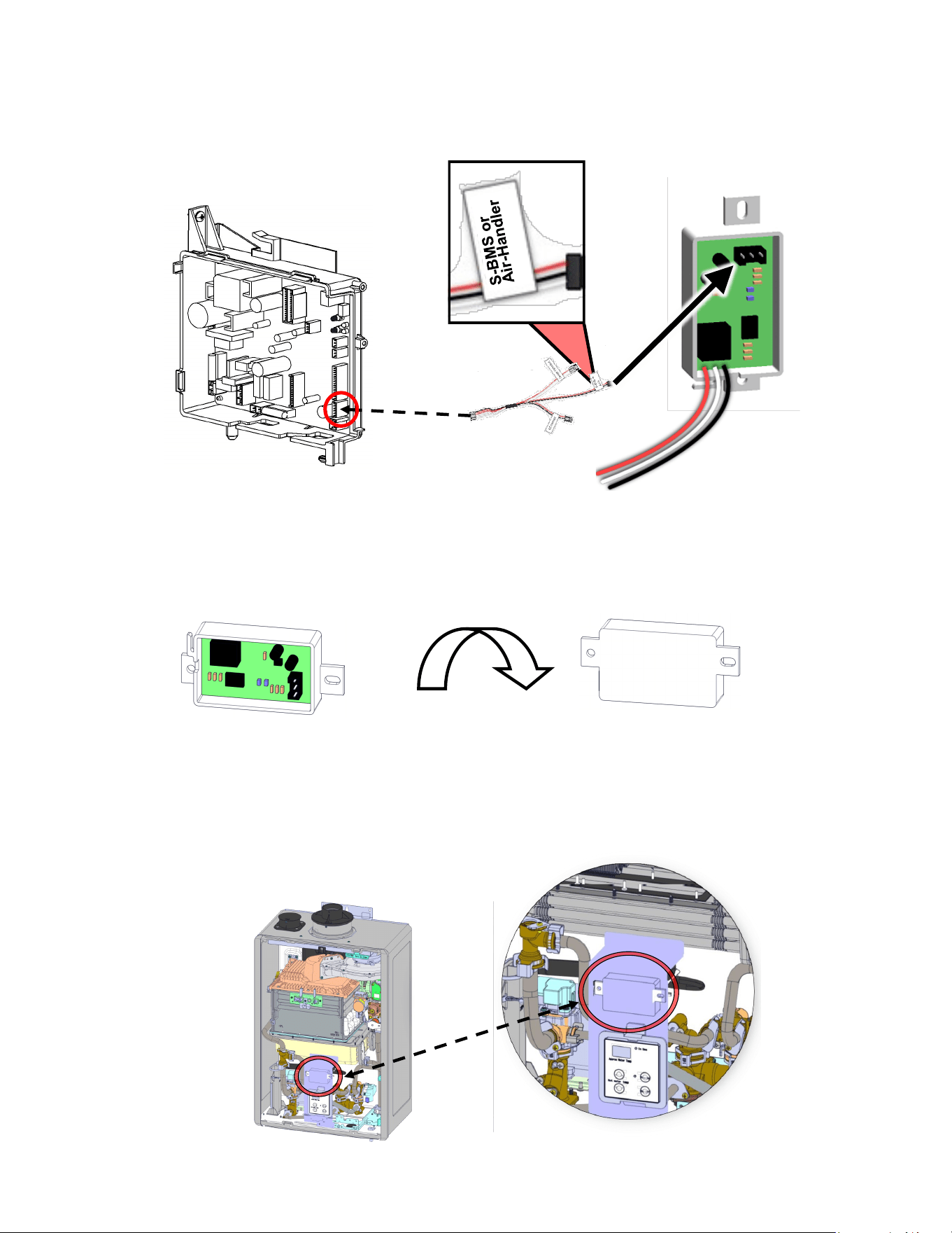
1. Attach the harness plug from the Domestic
Priority Switch (black, white, and red) as
described in Table 1 (located on next page).
2. Install the hydronic air handler per the
instructions in the “S-BMS/Air Handler Switch
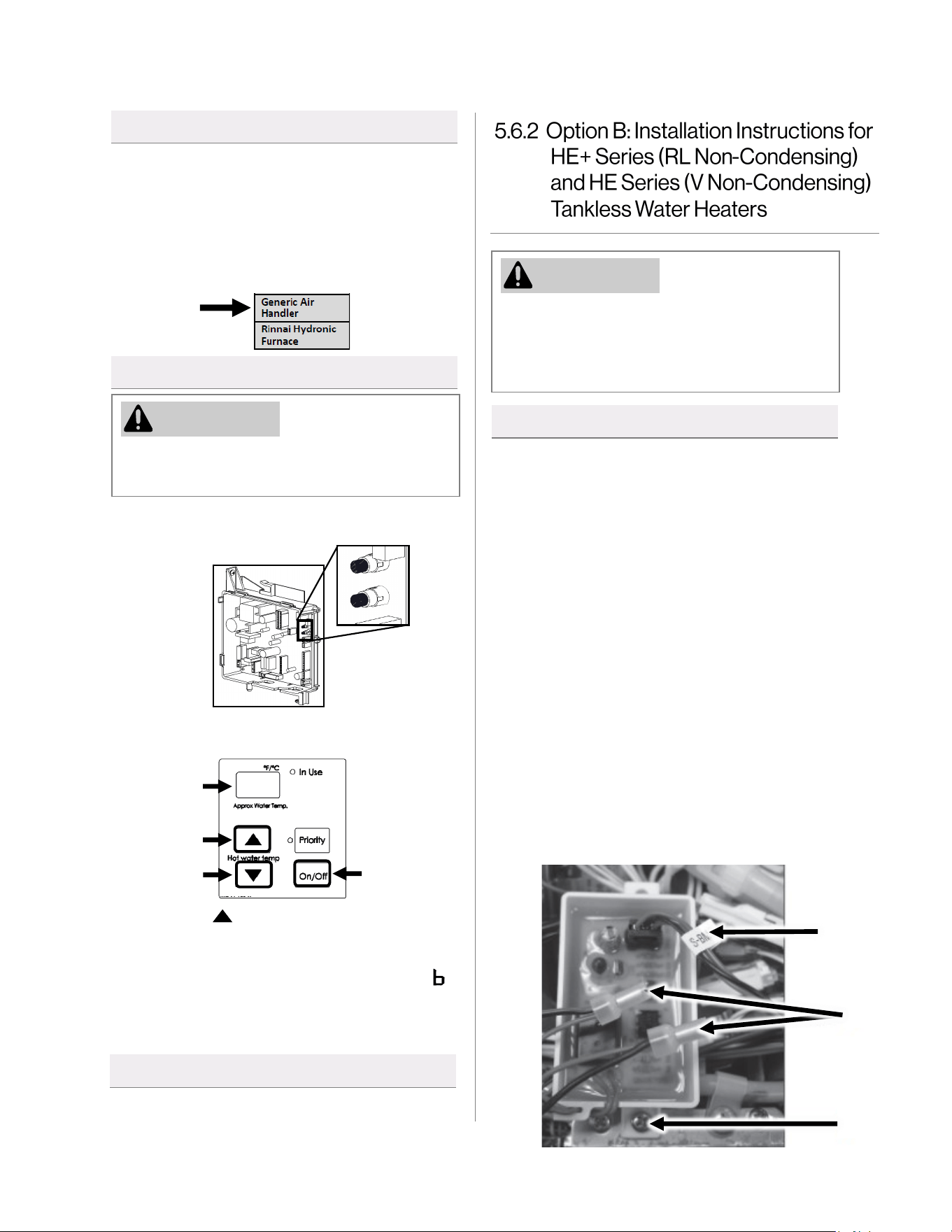
Installation Instructions.” Follow steps for a
“Generic Air Handler.”
WARNING
Adjust only the parameter settings listed
below. Do not adjust any other parameter
settings unless specifically instructed to do so.
3. Press the (Up) button until 0 6 A appears
on the display.
4. Press the On/Off button to change the
selection between 0 6 A for BMS and 0 6
for Air Handler (AH).
5. Selecting the primary water heater is
complete. Press the A button to exit.
1. Locate the two push buttons (A and B) on
the PC Board.
A
B
2. Press the A button for 1 second. 0 1 A
appears on the controller display.
0 1 A
WARNING
Ensure the power supply to the water heater
and hydronic air handler is disconnected before
starting installation. Removing the front cover
will expose live mains voltage connections.
1. Power OFF the tankless water heater or
boiler by unplugging the power cord or
turning off the circuit breaker. The controller
on the water heater or boiler does not
control the electrical power.
2. Remove the front panel of the water heater
or boiler.
3. Locate the wiring bundle and find the wiring
tagged “Air-H.” Temporarily remove the
cable tie and separate this connector from
the main bundle. Fasten the cable tie
around the remaining bundle.
4. Attach the switch circuit board using the
mounting screw provided (A in image
below). If required, adjust the position of the
main wiring bundle to provide enough room.
5. Attach the harness plug labeled “Air-H” to
the matching socket on the Domestic
Priority Switch (C in image below).
5.6.1.2 Wiring Instructions
5.6.1.3 Set Parameter Instructions
5.6.1.4 Next Steps
5.6.2.1 Install Switch Circuit Board
A
B
C
Proceed to section “5.6.4 Test the Switch After
Installation.”
30 Hydronic Air Handler Installaon and Operaon Manual
Table 1: Domestic Priority/Maintenance Indication with (DPS/MIS)
Switch Configuration
Required
Leads (Wires)
Connection Function
DIP Switch Configuration
ID Position
Air Handler (AH) - Generic
White and
Black
In series with
thermostat "W" wire
N.C.
Bank 1
(Yellow); #4
ON
N.C. = Normally Closed
Thermostat Wiring: Using the provided crimp connectors (B in image on previous page), connect the
white and black leads of the switch circuit board to the “W” contact on the indoor thermostat and air
handler (polarity is not important). See Table 1 below and the wiring diagrams in this section for
additional details. The final crimp connector should be connected to the unused red wire lead on the
switch circuit board.
5.6.2.2 Wiring Instructions
5.6.2.3 Set Parameter Instructions
5.6.2.4 Next Steps
Proceed to section “5.6.4 Test the Switch After Installation.”
Hydronic Air Handler Installaon and Operaon Manual 31
WARNING
Ensure the power supply to the boiler and hydronic air handler is disconnected
before starting installation. Removing the front cover will expose live mains
voltage connections.
To prevent cold air from being produced, it is recommended to set Parameter 42 to “A - Continuous
Run.” See the “Rinnai I-Series Boiler Installation and Operation Manual” for more information.
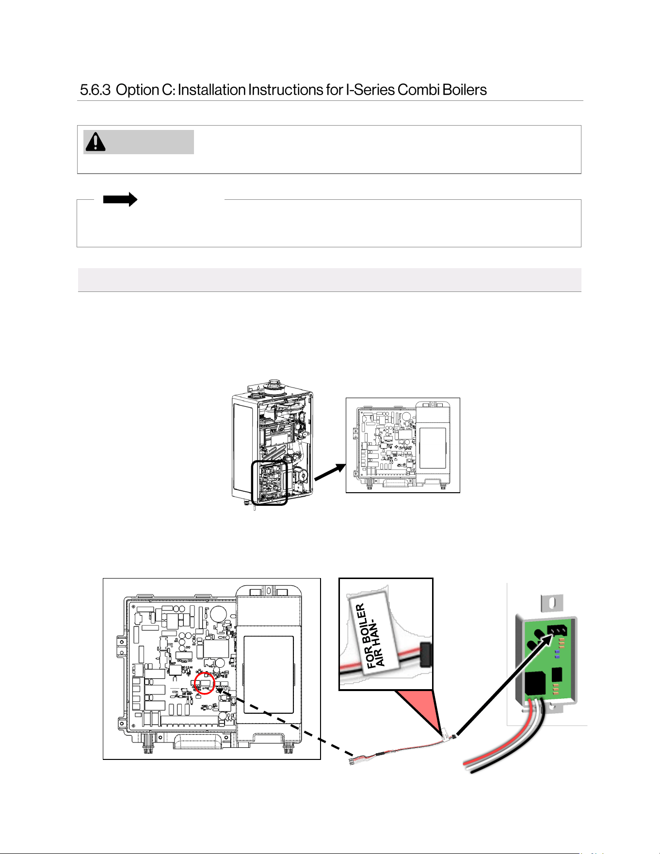
1. Power OFF the boiler by unplugging the power cord or turning off the circuit breaker. The controller
on the boiler does not control the electrical power.
2. Remove the front panel of the boiler by removing the four screws that secure the panel in place.
3. Locate the PC Board in the bottom, left corner of the boiler.
4. Connect one end of the boiler air handler cable to the accessory port on the PC Board. Connect the
other end of the cable to the switch circuit board accessory port.
5.6.3.1 Install Switch Circuit Board
IMPORTANT

32 Hydronic Air Handler Installaon and Operaon Manual
5. Attach the air handler/OPU circuit board to the PC Board via double-sided tape. Ensure the circuit
board does not make contact with the heat exchanger.
1. Attach the harness plug from the Domestic
Priority Switch (black, white, and red) as
described in Table 2.
2. Check all wiring and reattach the front
cover.
3. Reconnect power.
Table 2: Domestic Priority Configuration
Switch
Configuration
Required
Leads/Wires
Function
Generic Air
Handler
White/Black Normally Closed
External Pump
Connection 1
To Domestic
Priority Switch
PC Board Wiring for
the above
application example.
5.6.3.2 Wiring Instructions
5.6.3.3 Next Steps
Proceed to the next section: “5.6.4 Test the Switch After Installation.”
Boiler T/T1
Connected to Air
Handler T/T Terminal
Hydronic Air Handler Installaon and Operaon Manual 33
The domestic priority switch allows the tankless water heater or boiler to give priority to domestic hot
water by shutting off the air handler when necessary. When used with a hydronic air handler, the switch
gives priority to domestic hot water. When domestic hot water demand exceeds a certain point, the air
handler will turn off to ensure the demand is met.
To test this function:
1. Turn on the water heater/boiler and air handler.
2. Open the hot water taps until the air handler turns off.
3. Close the hot water taps.
4. The air handler should turn back on if the thermostat is calling for heat.
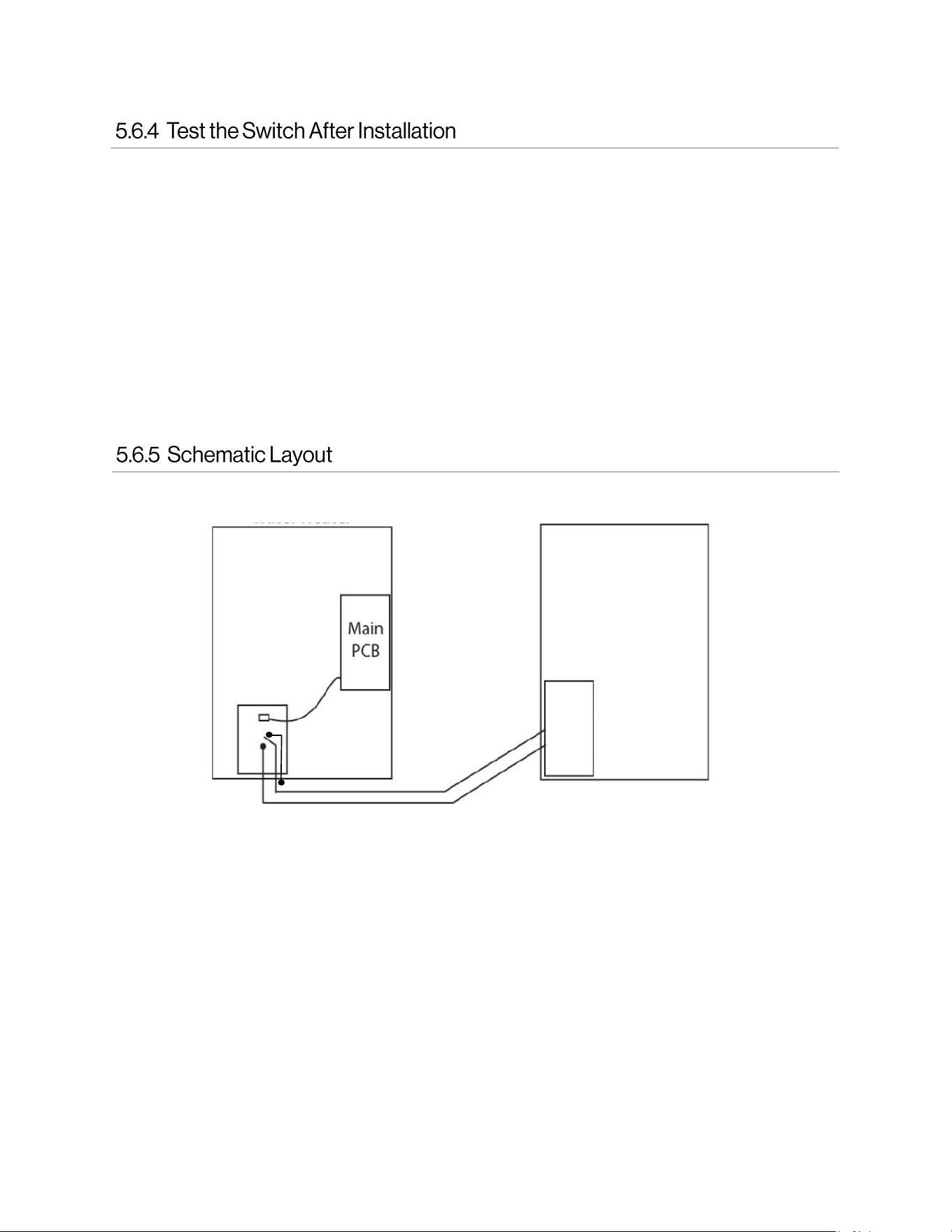
Rinnai Tankless Water Heater or Boiler
Air Handler
Control
Switch
Control
Panel
Air Handler
34 Hydronic Air Handler Installaon and Operaon Manual
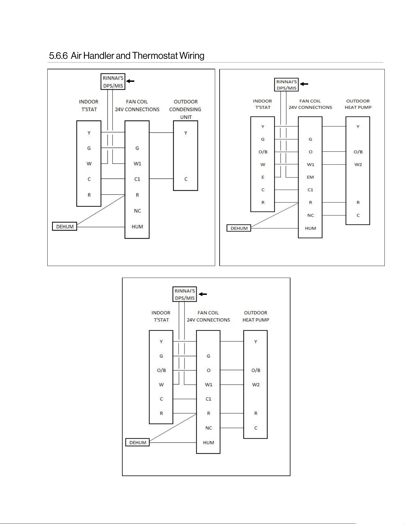
Single Stage A/C Cooling with Single Stage Heating
Single Stage Heat Pump
Y
Y
Domestic Priority Switch
Domestic Priority Switch
Single Stage Heat Pump with Auxiliary Backup Heat
Y
Domestic Priority Switch
Hydronic Air Handler Installaon and Operaon Manual 35
Gas Supply Line
Air Handler
Thermostat
Hot Water Supply Line
Building Outlets
Thermostac
Mixing Valve
Cold Water Supply Line
Condensate Drain Line as Appropriate
Recommended Rinnai
Domesc Priority Switch
Air handler models
with an internal
circulation pump
include an integrated
flow check.
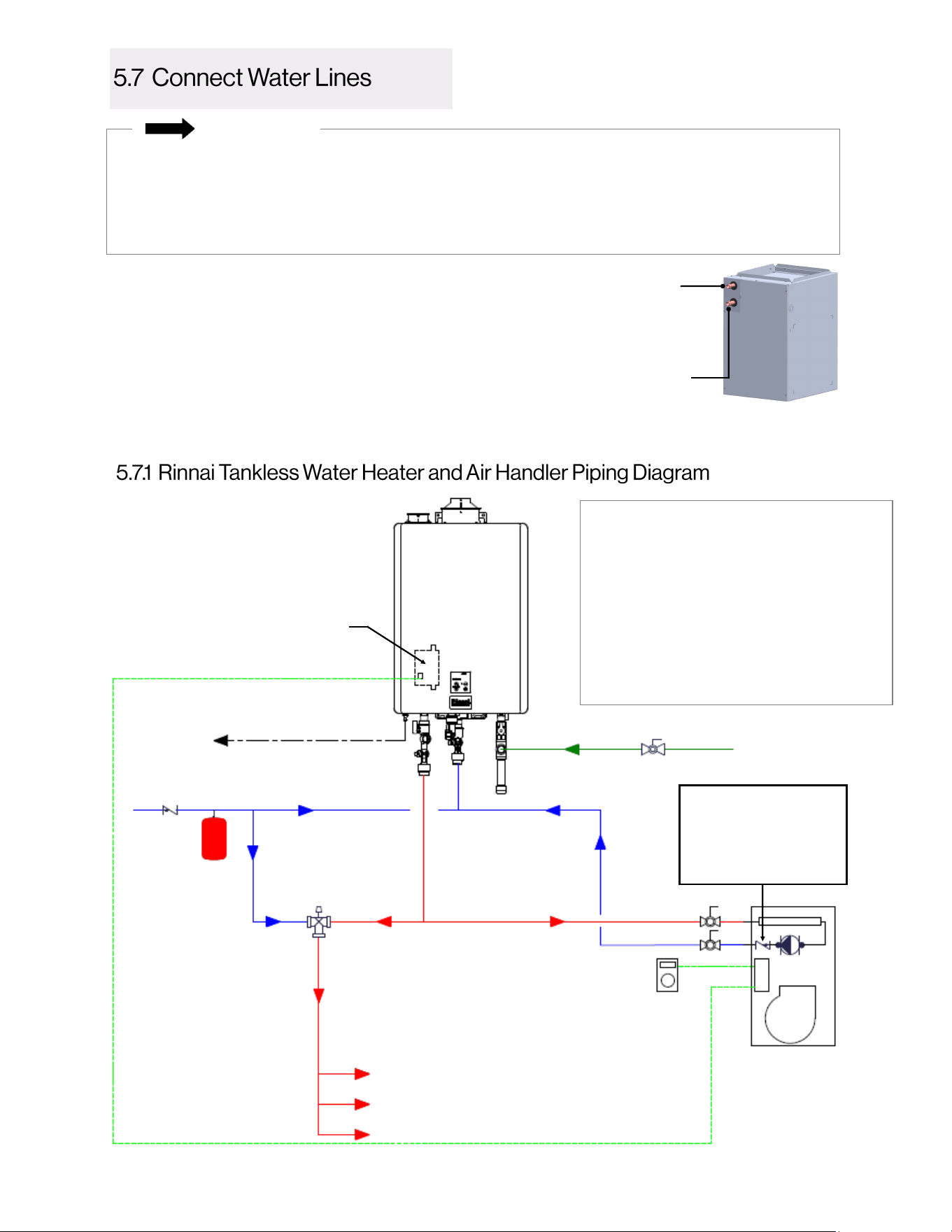
1. Plumb the water out/supply of the Rinnai tankless water
heater or boiler to the inlet (top connection) of the air
handler.
2. Plumb the air handler water outlet (bottom connection) to
the water inlet/return of the Rinnai tankless water heater or
boiler.
• Refer to section “4.8 Plumbing Requirements” for complete plumbing requirements.
• For standard installations, refer to the piping diagrams in sections 5.7.1 and 5.7.2.
• For more information on the tankless water heater or boiler plumbing connections, refer to the
unit’s Installation and Operation Manual.
• Water connections to the air handler should follow all state and local plumbing codes.
This is not an engineering drawing; it is intended
only as a guide and not as a replacement for
professional engineering project drawings. This
drawing is not intended to describe a complete
system. It is up to the contractor or engineer to
determine the necessary components and
conguraon of the parcular system to be installed.
The drawing does not imply compliance with local
building code requirements. It is the responsibility of
the contractor or engineer to ensure the installaon
is in accordance with all local building codes. Confer
with local building ocials before installaon.
Water Inlet
Cold Water From Air
Handler Returning to
Water Heater/Boiler
Hot Water From
Water Heater/
Boiler into Air
Handler
Water Outlet
IMPORTANT
See next page for Legend
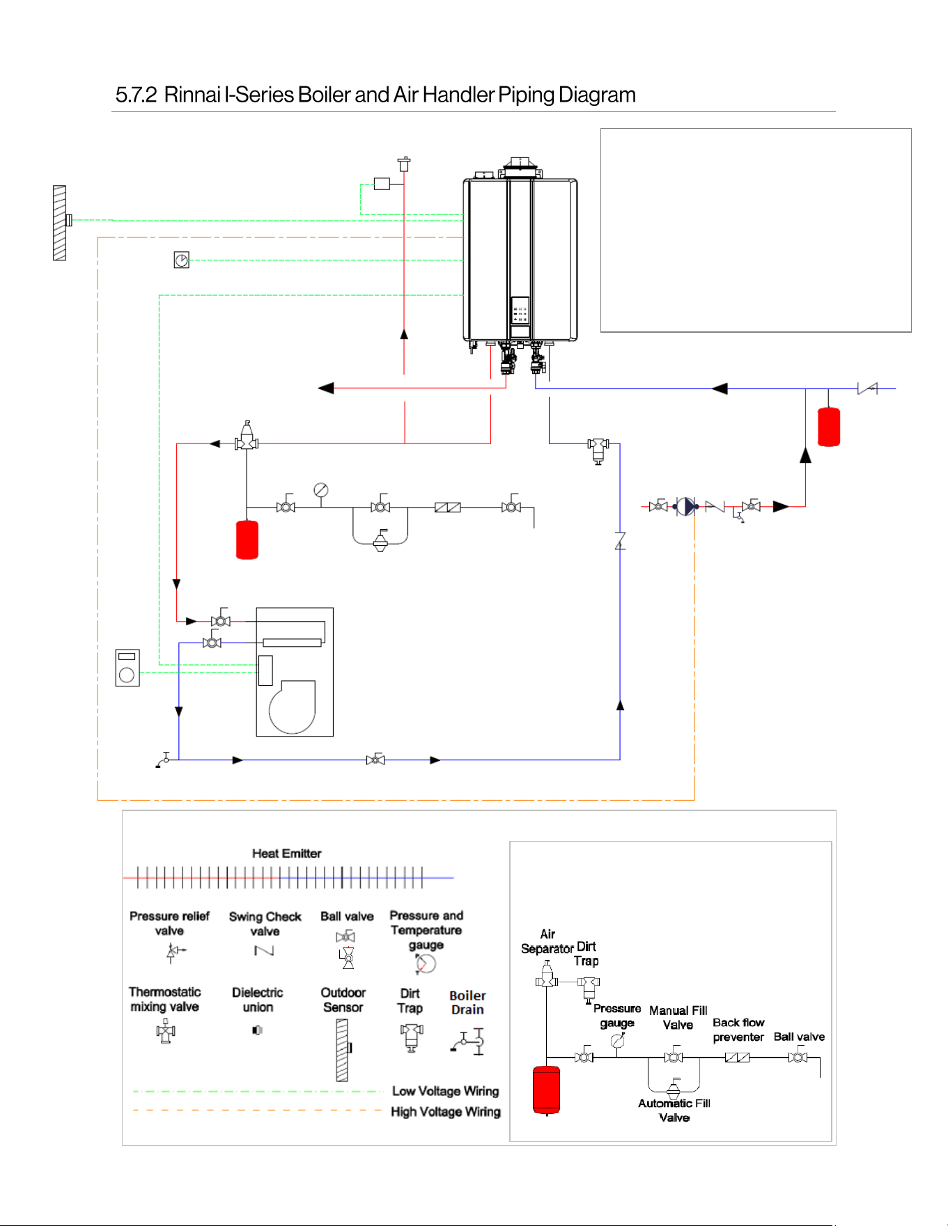
36 Hydronic Air Handler Installaon and Operaon Manual
The image below illustrates a suggested
arrangement. Some of the fittings are
optional.
LEGEND
This is not an engineering drawing; it is intended
only as a guide and not as a replacement for
professional engineering project drawings. This
drawing is not intended to describe a complete
system. It is up to the contractor or engineer to
determine the necessary components and
conguraon of the parcular system to be installed.
The drawing does not imply compliance with local
building code requirements. It is the responsibility of
the contractor or engineer to ensure the installaon
is in accordance with all local building codes. Confer
with local building ocials before installaon.
Outdoor Reset
Sensor
Oponal Low Water
Cut-O (LWCO)
DHW Recirculaon Timer (Oponal)
Domesc Hot Water Supply Line
Cold Water Supply Line
Thermostat
Air Handler
DHW
Recirculaon
Pump
(Oponal)
Domesc Hot
Water Return
Line (Not
Required)
Heang
Supply
Heang
Return
Hydronic Air Handler Installaon and Operaon Manual 37
This is not an engineering drawing; it is intended only as a guide and not as a replacement for professional engineering project
drawings. This drawing is not intended to describe a complete system. It is up to the contractor or engineer to determine the
necessary components and conguraon of the parcular system to be installed. The drawing does not imply compliance with
local building code requirements. It is the responsibility of the contractor or engineer to ensure the installaon is in
accordance with all local building codes. Confer with local building ocials before installaon.
Cold Water
Supply Line
Gas Supply Line
Hot Water Outlets
Thermostat
Thermostac
Mixing Valve
Rinnai Hydronic Air Handler with
Integrated Pump and Check Valve
Aquastat Connecon
Condensaon Drain Line as Appropriate
Recommended Rinnai
Domesc Priority Switch
• Schematic does not apply to Rinnai Tankless Water Heaters equipped with recirculation capability:
SE+ Series featuring ThermaCirc360™ models (Super High-Efficiency Plus RUR Models)
• Wire solenoid to 24V valve connection on air handler.
NOTE
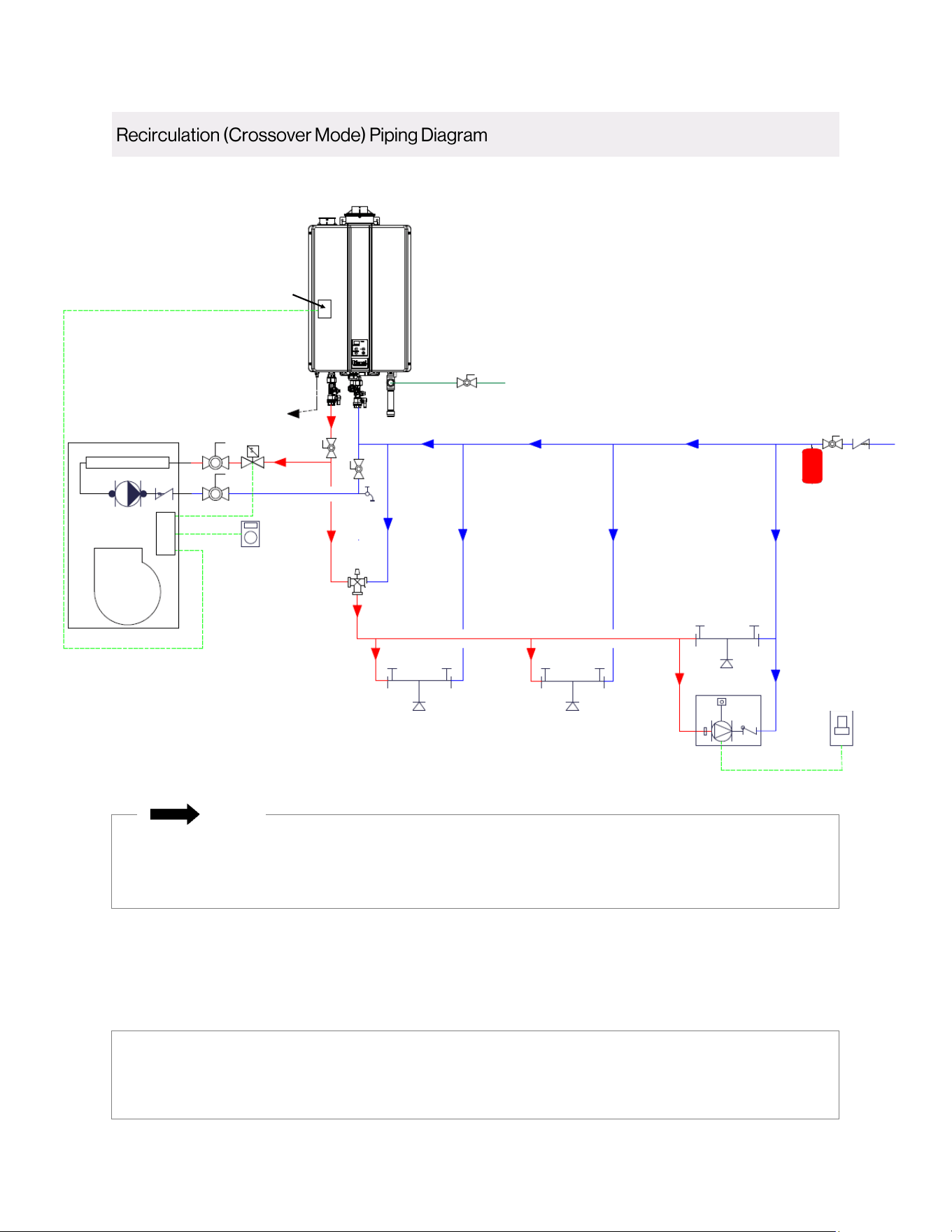
38 Hydronic Air Handler Installaon and Operaon Manual
This is not an engineering drawing; it is intended only as a guide and not as a replacement for professional engineering project
drawings. This drawing is not intended to describe a complete system. It is up to the contractor or engineer to determine the
necessary components and conguraon of the parcular system to be installed. The drawing does not imply compliance with
local building code requirements. It is the responsibility of the contractor or engineer to ensure the installaon is in
accordance with all local building codes. Confer with local building ocials before installaon.
Demand
Circulaon
Cold Water
Supply Line
Thermostat
Thermostac
Mixing Valve
Rinnai Hydronic Air Handler with
Integrated Pump and Check Valve
Condensaon Drain Line
as Appropriate
Recommended Rinnai
Domesc Priority Switch
Gas Supply Line
On-Demand
Recirculaon
Component (Push
Buon, Moon
Sensor, etc.)
• Schematic does not apply to Rinnai Tankless Water Heaters equipped with recirculation capability:
SE+ Series featuring ThermaCirc360™ models (Super High-Efficiency Plus RUR Models)
• Wire solenoid to 24V valve connection on air handler.
NOTE
Hydronic Air Handler Installaon and Operaon Manual 39
• Follow piping manufacturer’s
requirements for any additional required
flushing or cleaning of coil and piping if
using non-copper piping.
• Do not engage pump until the flushing
process is completed. Running pump dry
will cause damage.
CAUTION
Flushing the hot water coil prior to start up is
required to remove any residual material from the
installation or manufacturing processes as well
as remove any air from the system.
A bleed valve comes standard on all air handlers
with factory installed circulating pumps. If using
an external circulating pump, please use an
external purge valve or other mechanism to flush
hot water coil after installation. Take precautions
while flushing the air handler to keep the multi-
function control board and other electrical
components from getting wet. Hot water is
preferred for flushing.
Follow the flushing steps listed below. Use a
bucket or hose to dispose of water from the bleed
valve during flushing.
1. Flush the return line by closing the inlet valve
(supply) and opening the outlet valve (return).
Open the bleed valve. Close the bleed valve
when flushing is complete.
2. Flush the supply line and coil by closing the
outlet valve (return) and opening the inlet
valve (supply). Open the bleed valve. Close
the bleed valve when flushing complete.
3. Apply power to the air handler. Open inlet
and outlet valves. Engage pump and open
bleed valve. Verify proper flow direction—
inlet should become warm before outlet.
Close the bleed valve when flushing is
complete.
4. Operate pump for five minutes immediately
after flushing system to purge remaining air
from the pump bearing chamber.
The following conditions must be met prior to starting
the air handler. Refer to outdoor condensing unit
installation instructions for system start-up instructions
and refrigerant charging instructions.
Is unit properly located, secure, and
serviceable?
Is the unit elevated when installed in a garage
or where flammable vapers may be present?
Is the unit protected from vehicular or other
physical damage?
Is the return air not obtained from areas where
there may be objectionable odors, flammable
vapors or products of combustion such as
carbon monoxide (CO), which may cause
serious personal injury or death?
Does the air handler and evaporator coil exhibit
a ¾ in. pitch in the horizontal position towards
the drain pan to ensure proper condensate
drainage?
Has an auxiliary pan been provided under the
unit with separate drain for units installed above
a finished ceiling or in any installation where
condensate overflows could cause damage?
Auxiliary drain is installed when necessary and
pitched to allow for draining?
Has the drain pan and drain tubing been leak
checked?
Have all webs been removed from the drain
connections that are being used? Have all drain
pan plugs not used been properly plugged?
Has the condensate line been properly sized,
run, trapped, pitched, and tested?
Is the ductwork correctly sized, run, taped, and
insulated?
Have all cabinet openings and wiring been
sealed?
Is the indoor coil orifice size correct?
Have all unused orifice replacement parts and
packaging been disposed of or recycled?
Is the filter clean, in place, and of adequate
size?
Are all electrical connections properly sized and
tightened?
Is the wiring neat, correct, and in accordance
with the wiring diagram?
Is the unit properly grounded and protected
(fused)?
Is the thermostat correctly wired and in a good
location?
Are all access panels in place and secure? For
air tight application, neoprene gasket must be
positioned at prescribed locations to achieve
2% leakage.
Check Blower Operation: Set the thermostat
to “FAN ON.” Does the indoor blower turn on?
Continued on next page
40 Hydronic Air Handler Installaon and Operaon Manual
For blower performance data, refer to section “3.8.4 Blower Performance Data.”
IMPORTANT
Air Flow Inspection:
• For proper cooling operation, the airflow through the indoor coil should be between 350 and
450 CFM per ton of cooling capacity (or 350 – 450 CFM per 12,000 BTU/HR) based on the
rating of the outdoor unit.
• The cooling blower speed is factory configured to provide correct airflow for an outdoor unit that
matches the maximum cooling capacity rating of the air handler.
• If the outdoor unit is smaller than the maximum cooling capacity rating for the air handler, the
cooling blower speed may need to be changed. Refer to section “3.8.4 Blower Performance
Data” for more information.
IMPORTANT: The cooling blower speed must be set to provide a minimum of 350 CFM airflow
per ton (12,000 BTU/hr) of outdoor cooling capacity.
• Air Handler Models AH083P/CP, AH084P/CP, AH125P/CP, AH206P/CP:
1. Disconnect all power supplies.
2. Remove the air handler access panel.
3. Locate the blue wire (Med) running from the blower motor to the control board.
4. Remove this blue wire from the control board and cover this loose end of this wire now
with an insulating cap.
5. Locate the Red or Black wires connected to the blower motor. Connect the Red (Low) to
the control board at its respective terminal for low speed or connect the Black (High) to
the control board at its respective terminal for high speed.
6. Replace all panels.
7. Reconnect power.
• Air Handler Models AH166P/CP:
1. Disconnect all power supplies.
2. Remove the air handler access panel.
3. Locate the black wire (High) running from the blower motor to the control board.
4. Remove this black wire from the control board and cover this loose end of this wire now
with an insulating cap.
5. Locate the Blue or Red wires connected to the blower motor. Connect the Blue (Med) to
the control board at its respective terminal for medium speed or connect the Red (Low)
to the control board at its respective terminal for low speed.
6. Replace all panels.
7. Reconnect power.
Hydronic Air Handler Installaon and Operaon Manual 41
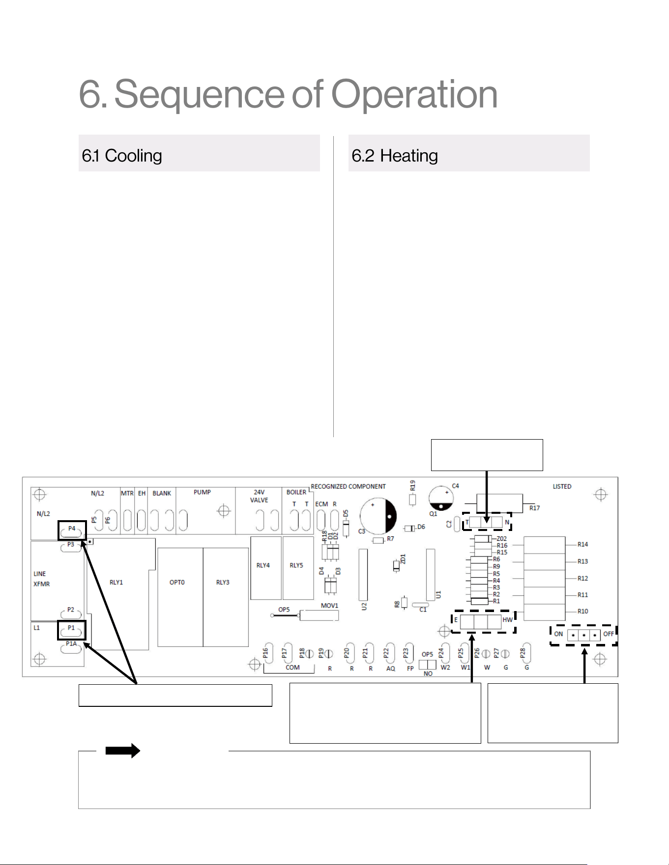
• When the thermostat calls for cooling, the
thermostat circuit between R and G is
completed.
• The normally open contacts close, causing
the indoor blower motor to operate.
• The thermostat circuit between R and Y is
also completed; this circuit closes the
contactor in the outdoor fan motor.
• Thermostat circuits R and O, or R and B,
energizes the reversing valve, switching it to
the cooling position (depends on outdoor
HVAC unit).
• The air handler blower will turn off 45
seconds after the thermostat stops calling
for cooling.
• When the thermostat calls for heat, the
thermostat circuit between R and W is
completed, activating the hot water
circulating pump.
• If a field-installed circulating pump is being
used, the control board can still be wired to
the pump directly or to an isolation valve
supplying hot water to the air handler using
the control board’s 24V relay switch. A
similar 24V dry switching relay labeled TT
can be used to activate a boiler or water
heater valve.
• A time delay of 60 seconds follows before
the thermostat circuit between R and G are
complete, activating the blower motor.
• The thermostat circuit between R and W is
completed.
• The air handler blower will turn off 30
seconds after the thermostat stops calling
for heating.
Control Board Located Inside Air Handler
• The Blower Door Safety Switch circuit (across P4 and P1 connections shown above) must be
complete for all sequence of operations to take place.
• During installation, use caution to not let the control board and other controls get wet.
IMPORTANT
Test Pins
(No Jumper Installed)
Jumper Selection Pins
(Jumper Installed in
OFF Position)
Heat Selection Pins
• E = Electric Heat (Not Applicable)
• HW = Hot Water Heater
(Jumper installed on HW)
Blower Door Safety Switch Circuit
42 Hydronic Air Handler Installaon and Operaon Manual
If the temperature of the water within the hot
water coil were to drop below 40°F, the
thermostat circuit between R and W is
completed, activating the hot water circulating
pump, external circulating pump or isolation
valve. When the water temperature rises above
70°F, the thermostat circuit between R and W is
opened and hot water will stop circulating within
the hot water coil.
To prevent the freeze protection from activating
the water circulating pump when in cooling
mode, move freeze stat to far left or far right of
water coil, and insulate with foam tape
insulation.
The State of Massachusetts requires the use of
a pump timer on domestic water applications to
periodically circulate water during the off cycle.
This pump timer requirement is a standard,
factory-installed feature on this air handler. The
pump timer activates the circulating pump or
isolation valve for one minute every six hours by
completing the thermostat circuit between R and
W. The pump timer is skipped while the outdoor
compressor is operating.
WARNING
Electrical Shock:
• Before servicing the air handler, turn off power
to unit. There may be more than one
disconnect switch.
• Improper installation, modification, service,
maintenance or use of the air handler can
cause electrical shock, burns or other
conditions which may cause electrical shock,
personal injury, property damage or death.
WARNING
To service the air handler, follow the steps below.
1. Turn off power to the unit.
2. Remove the four screws securing the front panel.
3. Perform service or maintenance to the air handler,
and then reinstall the four screws to secure the front
panel.
Maintenance:
• At the beginning of each heating season, the air
handler should be serviced by a qualified installer or
servicing agency. Verify proper operation after
servicing.
• It is important that compartments, filter, and
circulating air passage ways of the appliance be kept
clean.
• The supply and return air ducts should be inspected
at least annually for blockages or damage.
• Keep the motor free of dust and dirt by cleaning
annually.
• It is recommended that a trained and qualified
professional who has attended a Rinnai
installation training class perform service to the
air handler.
• Do not use this air handler if any part has been
under water. Immediately call a licensed
professional to inspect the unit and replace any
part that has been under water.
• Do not use substitute materials. Use only parts
certified for the air handler.
• Any alteration to the air handler can be
dangerous and will void the warranty.
The factory-installed freeze protection on all
air handlers is designed to protect the coil
from freezing. The installer must take steps to
protect the water piping from freezing.
Insulating the piping is highly recommended.
IMPORTANT
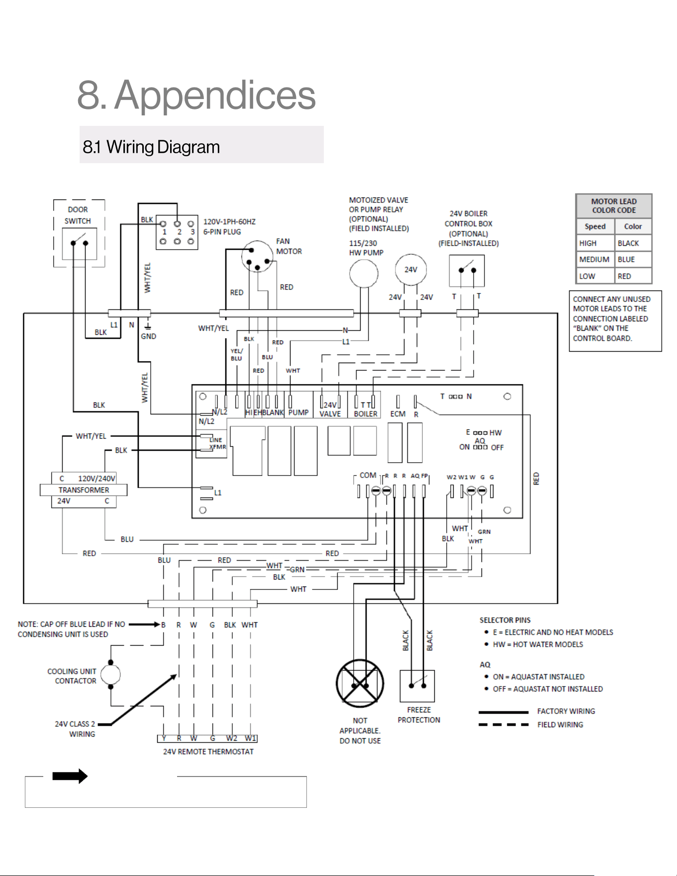
Hydronic Air Handler Installaon and Operaon Manual 43
Specific blower wire connections may vary by model.
IMPORTANT
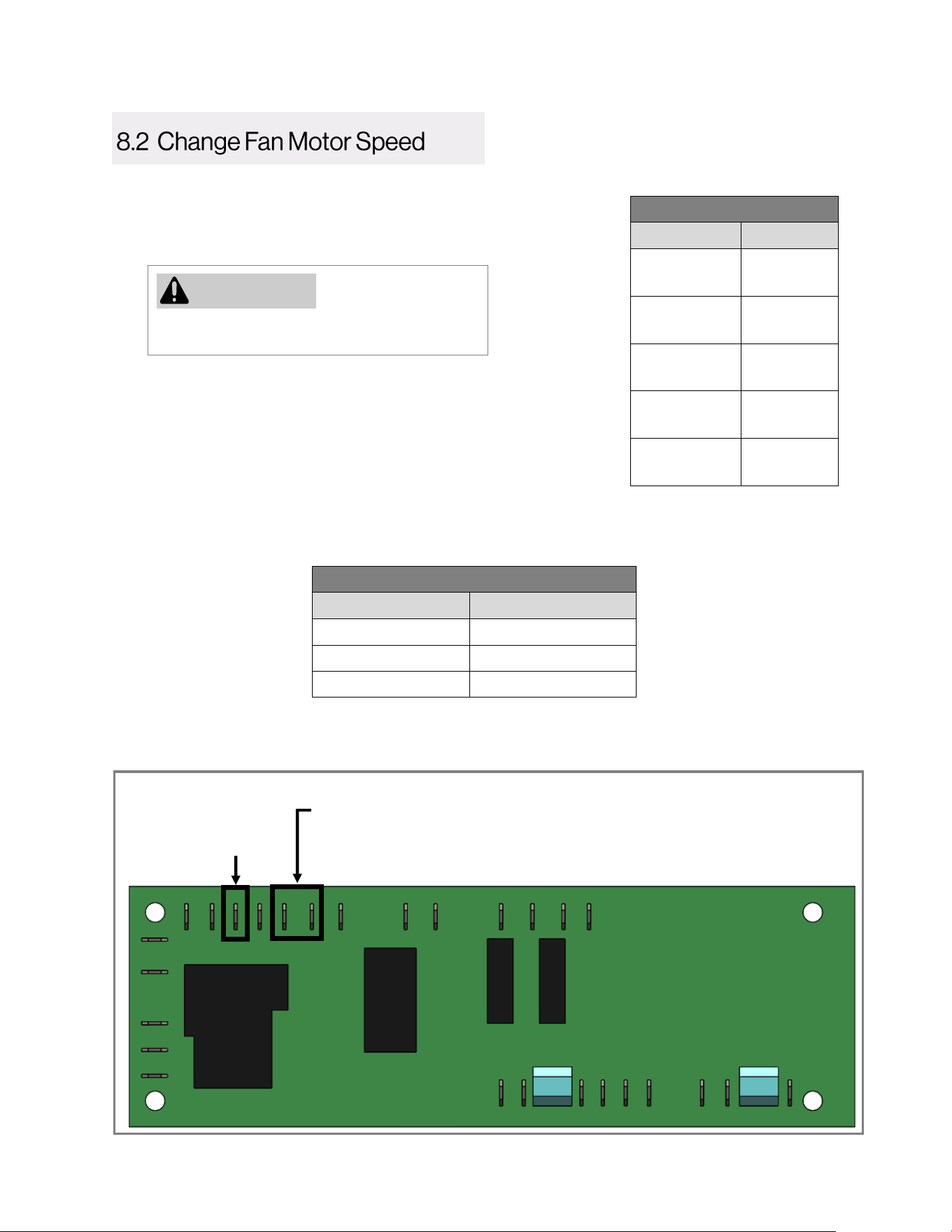
44 Hydronic Air Handler Installaon and Operaon Manual
❶
❷
2. Remove the air handler access panel by removing the four
screws that secure the panel.
3. Locate the PC Board.
4. On the PC Board, remove the wire lead from the “MTR” tap (this
tap controls the fan motor speed). See in image below.
Default Setting Speeds
Model Speed
• AH083CP
• AH083P
Medium
• AH084CP
• AH084P
Medium
• AH125CP
• AH125P
Medium
• AH166CP
• AH166P
High
• AH206CP
• AH206P
High
Failure to not disconnect power can result in
electrical shock, personal injury or death.
WARNING
Fan Motor Speed Wire Lead Color Code
Speed Color
High Black
Medium Blue
Low Red
6. Connect the unused wire lead to the “Blank” tap.
7. Replace the air handler access panel.
The speed of the air handler is factory default set as per the table to
the right. To adjust speed settings, follow the steps below:
1. Disconnect power to the air handler.
5. Remove the desired wire lead from the “Blank” tap and place in the “MTR” tap (the “Blank” tap is
where unused fan motor speed wire leads are stored). See in image below. Refer to the
following table for wire lead color descriptions:
❶
❷
MTR Tap
(Controls fan
motor speed)
MTR
Blank
Blank Tap
(Stores unused fan motor
speed wire leads)
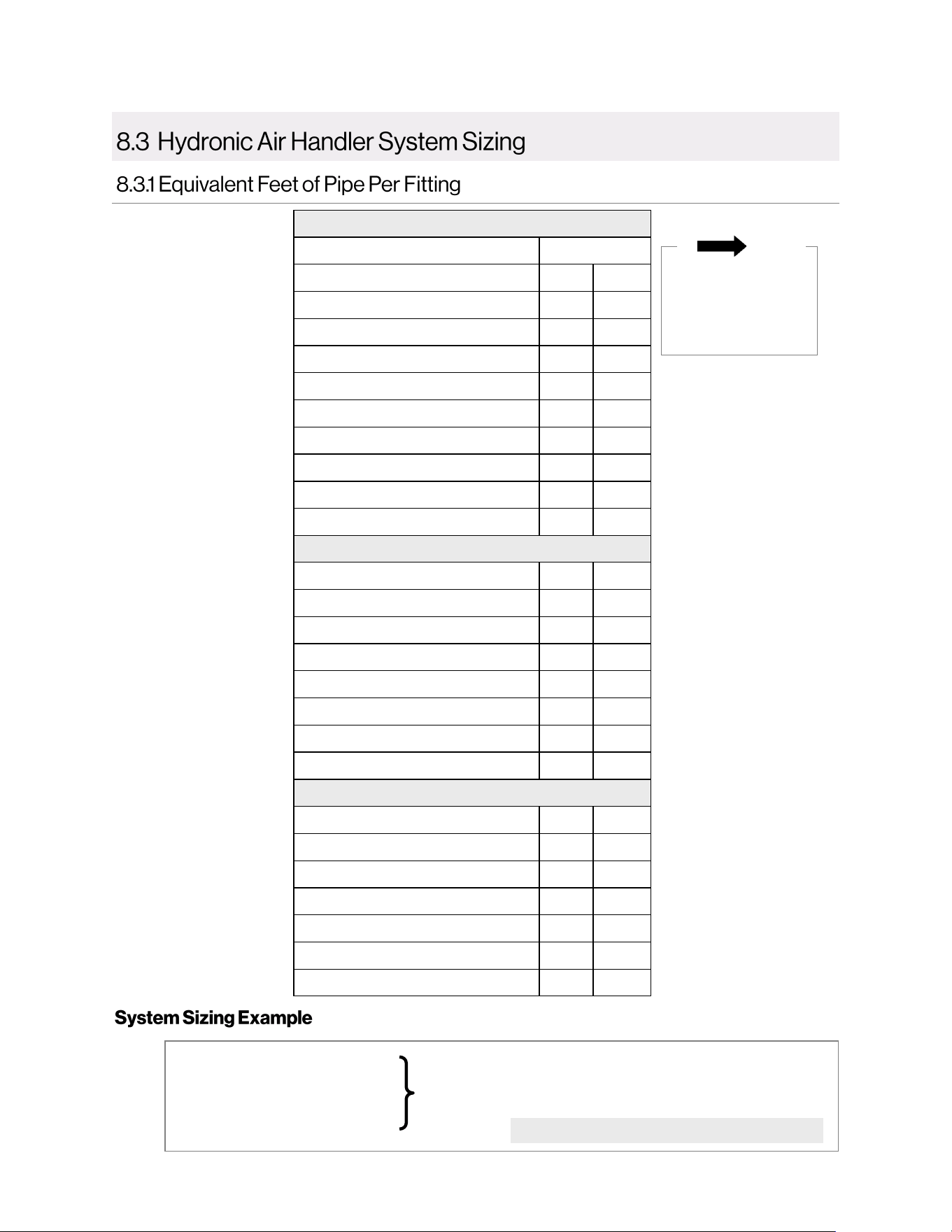
Hydronic Air Handler Installaon and Operaon Manual 45
NOTE
All values have
been normalized to
3/4 in. copper pipe
as a baseline.
Copper
Diameter
Fitting 3/4 in. 1 in.
90 Degree Elbow 2 0.75
45 Degree Elbow 0.75 0.3
Straight Through Tee 0.4 0.135
Side Port Tee 3 1.35
Reducer Coupling 0.5 0.18
Gate Valve 0.25 0.09
Ball Valve 2.2 1.29
Swing Check Valve 3 1.35
Multiplier Per Linear Foot of Pipe 1 0.3
PEX
Fitting 3/4 in. 1 in.
90 Degree Elbow 19.44 6.9
Straight Through Tee 2.7 0.78
Side Port Tee 28.08 7.62
Reducer Coupling 4.68 1.62
Ball Valve 5.94 2.58
PEX x NPT 4.86 2.28
Multiplier Per Linear Foot of Pipe 1.8 0.6
CPVC
Fitting 3/4 in. 1 in.
90 Degree Elbow 2.2 1
45 Degree Elbow 1.21 0.56
Straight Through Tee 1.54 0.68
Side Port Tee 5.5 2.4
Male/Female Adapter 1.65 0.8
Multiplier Per Linear Foot of Pipe 1.1 0.4
• 50 ft. of 3/4 in. CPVC pipe
• Four (4) 90 degree elbows
• Two (2) straight through tees
Total
Equivalent
Length
= 50 x 1.1 (Total linear foot equivalency)
+ 4 x 2.2 (Total for 90 degree elbows)
+ 2 x 1.54 (Total for tees)
Approximately 67 Equivalent Feet of Piping
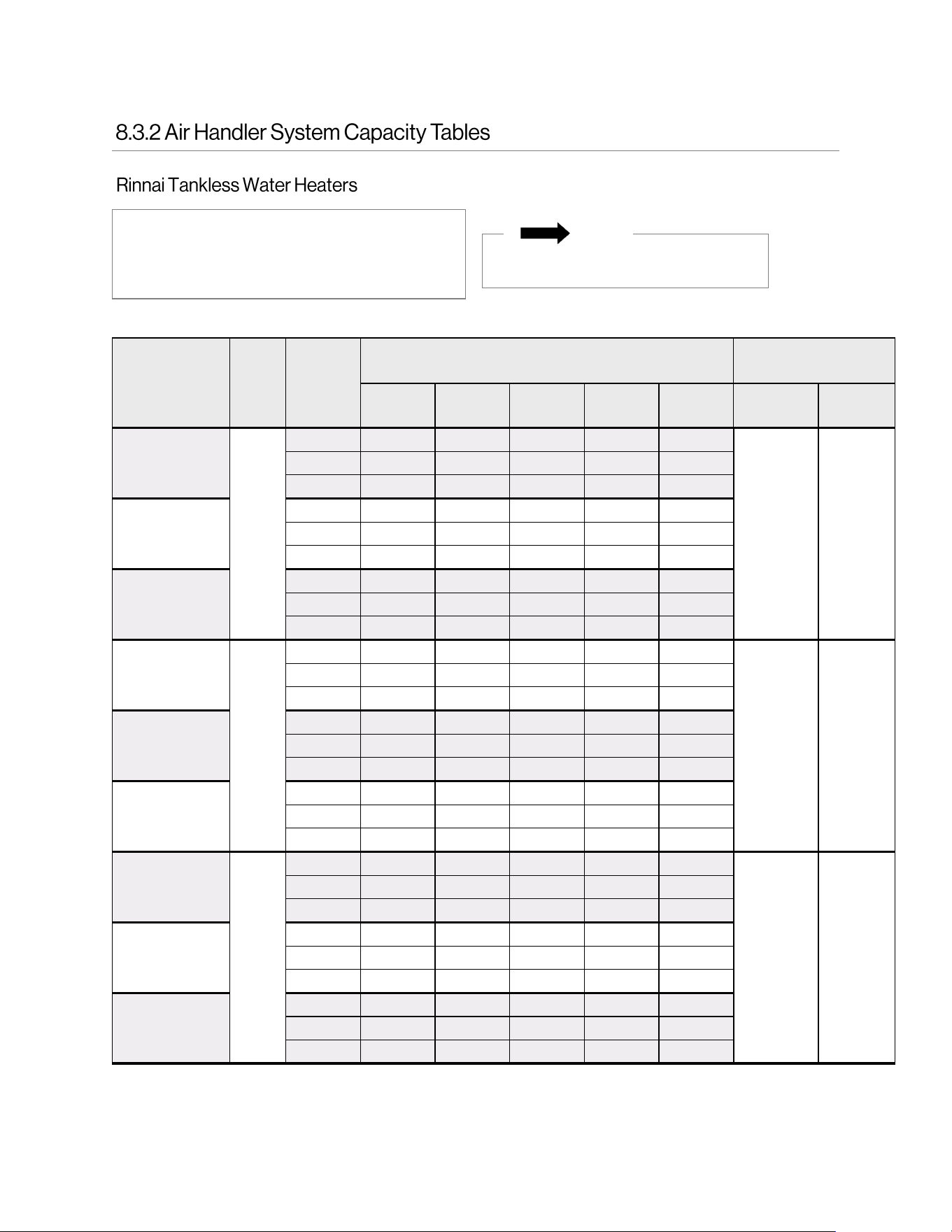
46 Hydronic Air Handler Installaon and Operaon Manual
Models:
• SENSEI™ SE+ Series (RU Condensing)
• HE+ Series (RL Non-Condensing)
• HE Series (V Non-Condensing)
Entering Water
Temperature
Flow
Rate
Blower
Speed
Seng
BTU Output
(Air Handler Models)
Maximum Equivalent
Pipe Length (.)
1
AH083CP AH084CP AH125CP AH166CP AH206CP
SENSEI™
SE+
HE+ and
HE
120°F
2
Low 18,000 20,000 26,000 31,000 30,000
100 100
Medium 19,000 22,000 27,000 32,000 30,000
High 20,000 23,000 28,000 33,000 30,000
140°F
Low 25,000 28,000 37,000 44,000 42,000
Medium 27,000 30,000 38,000 45,000 42,000
High 29,000 32,000 40,000 46,000 43,000
160°F
Low 33,000 36,000 48,000 57,000 54,000
Medium 35,000 39,000 50,000 58,000 55,000
High 37,000 42,000 51,000 59,000 56,000
120°F
3
Low 20,000 22,000 30,000 37,000 36,000
50 70
Medium 21,000 24,000 32,000 38,000 37,000
High 23,000 26,000 33,000 39,000 37,000
140°F
Low 25,000 31,000 42,000 53,000 51,000
Medium 30,000 34,000 45,000 54,000 52,000
High 32,000 37,000 46,000 56,000 53,000
160°F
Low 33,000 40,000 55,000 68,000 66,000
Medium 39,000 44,000 58,000 70,000 68,000
High 42,000 48,000 60,000 72,000 69,000
120°F
4
Low 21,000 23,000 32,000 41,000 40,000
10 20
Medium 23,000 26,000 34,000 43,000 41,000
High 24,000 28,000 36,000 44,000 42,000
140°F
Low 29,000 32,000 46,000 58,000 57,000
Medium 32,000 36,000 48,000 60,000 58,000
High 35,000 39,000 51,000 62,000 60,000
160°F
Low 38,000 42,000 59,000 75,000 74,000
Medium 41,000 47,000 62,000 78,000 76,000
High 45,000 51,000 66,000 80,000 77,000
NOTE
Tankless water heaters must have a
minimum input rate of 160,000 Btu/hr.
1
Refer to section “8.3.1 Equivalent Feet of Pipe Per Fitting” for more information on determining the maximum
equivalent pipe length.
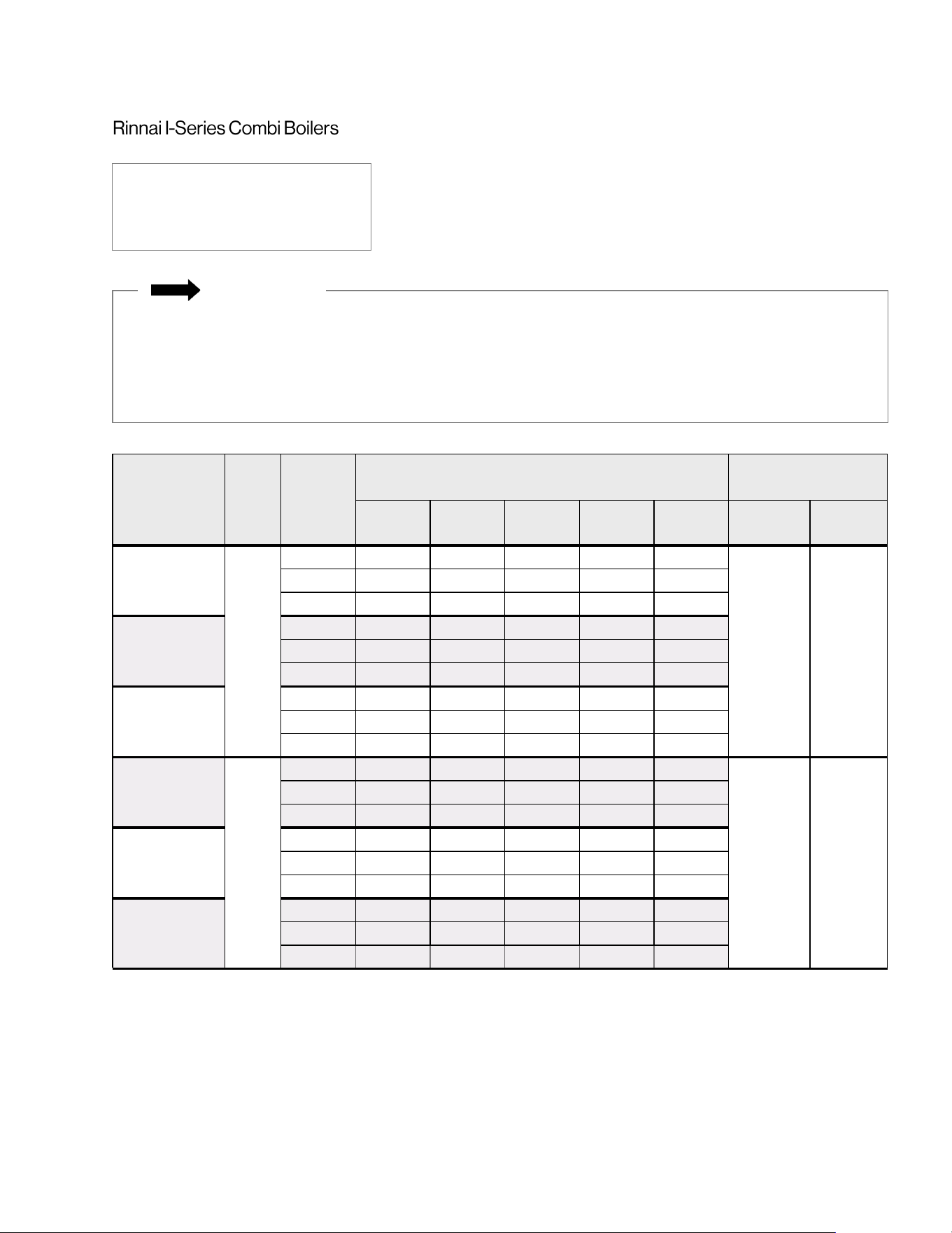
Hydronic Air Handler Installaon and Operaon Manual 47
Entering Water
Temperature
Flow
Rate
Blower
Speed
Seng
BTU Output
(Air Handler Models)
Maximum Equivalent
Pipe Length (.)
1
AH083P AH084P AH125P AH166P AH206P
i060C/
i090C
i120C
120°F
3
Low 20,000 22,000 30,000 37,000 36,000
40 40
Medium 21,000 24,000 32,000 38,000 37,000
High 23,000 26,000 33,000 39,000 37,000
140°F
Low 25,000 31,000 42,000 53,000 51,000
Medium 30,000 34,000 45,000 54,000 52,000
High 32,000 37,000 46,000 56,000 53,000
160°F
Low 33,000 40,000 55,000 68,000 66,000
Medium 39,000 44,000 58,000 70,000 68,000
High 42,000 48,000 60,000 72,000 69,000
120°F
4
Low 21,000 23,000 32,000 41,000 40,000
10 10
Medium 23,000 26,000 34,000 43,000 41,000
High 24,000 28,000 36,000 44,000 42,000
140°F
Low 29,000 32,000 46,000 58,000 57,000
Medium 32,000 36,000 48,000 60,000 58,000
High 35,000 39,000 51,000 62,000 60,000
160°F
Low 38,000 42,000 59,000 75,000 74,000
Medium 41,000 47,000 62,000 78,000 76,000
High 45,000 51,000 66,000 80,000 77,000
Models:
• i060C
• i090C
• i120C
1
Refer to section “8.3.1 Equivalent Feet of Pipe Per Fitting” for more information on determining the maximum
equivalent pipe length.
IMPORTANT
If more than 40 equivalent feet of plumbing is needed with the I-Series Boiler, Rinnai recommends the use
of hydraulic separation with an external circulation pump. Hydraulic separation uses primary/secondary
piping to separate the boiler from the heating system. Hydraulic separator examples include a low loss
header (field-supplied), closely spaced tee (field-supplied), or the Primary-Secondary Heating Kit offered
by Rinnai (part # 807000212).
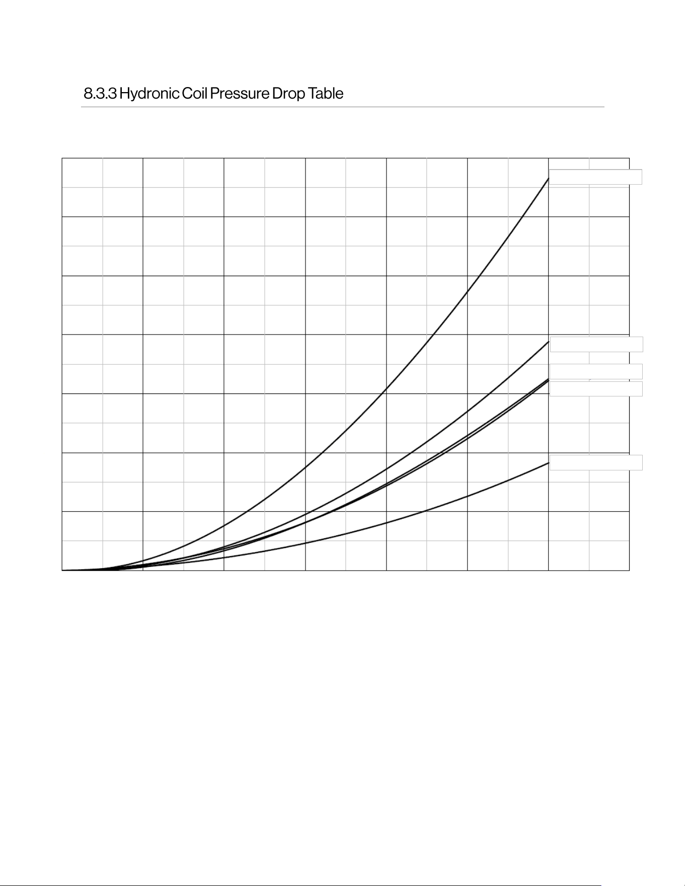
48 Hydronic Air Handler Installaon and Operaon Manual
Pressure Loss (Feet of Head)
14
12
10
8
6
4
2
0
0
1
2 3 4
5
6
7
AH125CP/AH125P
AH206CP/AH206P
AH084CP/AH084P
AH166CP/AH166P
AH083CP/AH083P
Water Flow (GPM)

Hydronic Air Handler Installaon and Operaon Manual 49

50 Hydronic Air Handler Installaon and Operaon Manual

Hydronic Air Handler Installaon and Operaon Manual 51