

About this Document
This manual is intended for administrators and users of the AXIS
M1143–L Network Camera, and is applicable to firmware 5.40 and
later. It includes instructions for using and managing the product on
your network. Previous experience of networking will be of use when
using this product. Some knowledge of UNIX or Linux-based systems
may also be beneficial, for developing shell s cripts and applications.
Laterversionsofthisdocumentwill be posted to the Axis website,
as required. See also the prod uct’ s online help, available via the
web-based interface.
Liability
Every care has been taken in the preparation of this manual. Please
inform your local Axis office of any inaccuracies or omissions. Axis
Communications AB cannot be held responsible for any technical or
typographical e rrors and reserves the right to make changes to the
product and manuals without prior notice. Axis Communications AB
makes no warranty of any kind with regard to the material c ontained
within this document, including, but not limited to, the implied
warranties of me rchantability and fitness for a particular p urpose. Axis
Communications AB shall not be liable nor responsib le for incidental or
consequential damages in connection with the furnishing, performance
or use of th is material. This product is only to be used for its intended
purpose.
Intellectual Property Rights
Axis AB has intellectua l property rights relating to technology embodied
in the product described in this document. In particular, and without
limitation, these intellectu al property rights may include one or more
of the patents listed at http://www.axis.com/patent.ht m and one or
more additional patents or pending patent applications in th e US and
other countries.
This product conta ins licensed third-party software. See the menu item
“About” in the product’s user interface for more information.
This product contains source code copyright Apple Computer,
Inc.,underthetermsofApplePublicSourceLicense2.0(see
http://www.opensource.ap ple.com/apsl). The source code is available
from http://developer.apple.com/darwin/projects/bonjou r/
Equipment M odifications
This equipment must be installed and u sed in strict accordance with the
instructions given in the user documentation. This equipment contains
no user-ser viceable components. Unauthorized equipment changes or
modifications will invalidate a ll applicable regulatory certifications
and approvals.
Trademark Acknowledgments
Apple, Boa, Bonjour, Ethernet, Internet Explorer, Linux , Microso
ft,
Mozilla, Real, SMPTE, Qui ckTime, UNIX, Windows, Win dows Vista and
WWW are registered tradema rks of the respective holders. Java and
all Java-based trademarks and logos are trademarks or registe
red
trademarks of Oracle and/or its affiliates. UPnP
TM
is a cer tification
mark of the UPnP
TM
Implementers Corporation.
Support
Should you require any technical assistance, please contact your Axis
reseller. If your questions cannot be answered immediately, your
reseller will forward your queries throu
gh the appropriate channels to
ensure a rapid response. If you are connected to the Internet, you can:
• download user documentation and software updates
• find answers to resolved problems in the FAQ database. Search
by product, category, or phrase
• report problems to Axis support staff by logging in to your private
support area
• chat with Axis sup port staff (selected countries only)
• visit Axis Support at www.axis.com/techsup/
Electromagnetic C om patibility (EMC)
This equipment has been designed and tested to fulfill applicable
standards for:
• Radio frequency emiss
ion when installed according to the
instructions a n d used in it s intended environm en t.
• Immunity to electrical and electromagnetic phenomena when
installed accor
ding to the instructions and used in its intended
environment.
USA
This equipment has been tested using a shielded network cable (STP)
and found to com p ly with the limits for a Class B digital device,
pursuant to part 15 of the FCC Rules . The se limits are designed
to provide reasonable protection against harmful interference in a
residential installation. This equipment generates, uses and can radiate
radio frequency energy and, if not installed and used in accordance
with the instructions, m ay cause harmful i nterference to radio
communications. However, there is no guarantee that interference
will not occur in a particular installation. If this equipment does
cause harmful interference to radio or television reception, which
can be determined by turning the equipment off and on, the user is
encouraged to try to correct the interference by one or more of the
following measures:
• Reorient or reloca te the receiving antenna.
• Increase the separation between the equipment and receiver.
• Connect the equipment into an outlet on a circuit differe nt from
that to which the receiver is conn ected.
• Consult the dealer or an experienced radio/TV technician for help.
Canada
This Class B d igita l apparatus complies w ith Canadian ICE S-003.
Europe
This digital equipment fulfills the requirements for RF emission
according to the C lass B lim it of E N 55022.
This product fulfills the requirements for immunity according
to EN 61000-6-1 residential, commercial and light-industrial
environments.
This product fulfills the requirements for immunity according to
EN 61000-6-2 industrial environments.
This product fulfills the requirements for immunity according to
EN 55024 office and commercial environm ents.
Australia/New Zealand
This digital equipme nt fulfills the requirement s for RF emission
according to the Class B limit of AS/NZS CISPR 22.
Korea
이 기기는 가정용(B급) 전자파적합기기로서 주로 가정에서 사
용하는 것을 목적으로 하며, 모든 지역에서 사용할 수 있습니다.
Japan
この装置は、クラスB 情報技術装置です。この装置は、家庭
環境で使用することを目 的としていますが、この装置がラジ
オやテレビジョン受信機に近接して使用されると、 受信障
害を引き起こすことがあります。 取扱説明書に従って正し
い取り扱いをして下さい。
Photobiological Safety
This product fulfills the requirements for photobiological safety
according to EN 62471.

AXIS M1143–L
Table of Contents
HardwareOverview .......................................... 4
Connectors .................................................... 4
LEDIndicators .................................................. 5
AccessingtheProduct ....................................... 6
AccessfromaBrowser ........................................... 6
AccessfromtheInternet .......................................... 7
SettheRootPassword ........................................... 7
TheLiveViewPage .............................................. 8
MediaStreams ............................................. 10
HowtoStreamH.264 ............................................ 10
MJPEG ........................................................ 10
AXISMediaControl(AMC) ........................................ 10
AlternativeMethodsofAccessingtheVideoStream .................... 11
SettingUptheProduct ...................................... 13
BasicSetup .................................................... 13
Video ......................................................... 14
VideoStream ................................................... 14
Stream Pro fi les ................................................. 15
CameraSettings ................................................ 16
ViewArea ..................................................... 17
Overlay ........................................................ 17
PrivacyMask ................................................... 18
Live View Config ............................................ 19
PTZ(PanTiltZoom) ......................................... 22
PresetPositions ................................................. 22
GuardTour ..................................................... 22
Advanced ...................................................... 23
Detectors .................................................. 24
CameraTampering .............................................. 24
MotionDetection ............................................... 24
Events .................................................... 27
SettingUpanActionRule ........................................ 28
Recipients ..................................................... 29
Schedules ...................................................... 29
Recurrences .................................................... 29
Recordings ................................................. 31
RecordingList .................................................. 31
ContinuousRecording ............................................ 31
SystemOptions ............................................. 33
Security ....................................................... 33
Date&Time .................................................... 36
Net
work .......................................................
37
Storage ....................................................... 41
Ports&Devices ................................................. 42
Maintenance ................................................... 42
Support ....................................................... 43
Advanced ...................................................... 44
ResettoFactoryDefaultSettings ................................... 44
Troubleshooting ............................................ 45
CheckingtheFirmware ........................................... 45
UpgradingtheFirmware .......................................... 45
EmergencyRecoveryProcedure .................................... 45
Symptoms,PossibleCausesandRemedialActions ..................... 46
Technical Specifications ...................................... 50
Connectors .................................................... 51
PerformanceConsiderations ....................................... 52
3
AXIS M1143–L
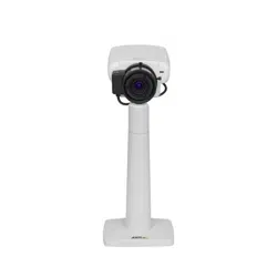
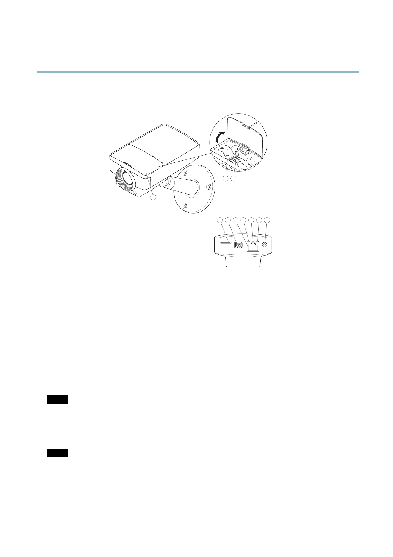
Hardware Overview
Hardware Overview
4 5 6
3
7
8 9
10
1
2
1.
Lid
2.
Focus p uller
3.
Zoom puller
4.
microSD card slot
5.
I/O connector
6.
Network connector (PoE)
7.
Network LED
8.
Status LED
9.
Power LED
10.
Control button
Connectors
For technical specifications, see
page 50
.
Network connector - RJ-45 Ethernet connector. Supports Power over Ethernet (PoE).
NOTICE
The pro duct shall be connected using a shielded network cable (STP). All cables connecting the product to the network switch
shall be shielded (STP) and intended for their specific use. Make sure that the network switch is properly grounded. See
Electromagnetic Compatibility (EMC )
for regulatory requirements.
SD card slot - A standard or high-capacity microSD card (not included) can be used for local recording with removab le storage.
NOTICE
To prevent corruption of recordings, the SD card should be unmounted before removal. To unmount, go to Setup > System
Option
s > Storage > SD Card and click Unmount.
Control button - The control button is used for:
4

AXIS M1143–L
Hardware Overview
• ConnectingtoanAXISVideoHostingSystemservice.See
page 37
. To connect, press and hold the button for about
1 second until the Status LED flashes green.
• ConnectingtoAXISInternetDynamicDNSService. See
page 38
. To connect, press and hold the button for
about 3 seconds.
• Resetting the p rod uct to fa ctory default settings. See
page 44
.
I/O terminal connector - Use in applica tions for e.g. motion detection, eve nt triggering, time lapse recording and alarm notifications.
In addition to an auxili ary pow e r and a GND pin, the I/O terminal connector provides the interface to:
• Digital output – For connecting external devices such as relays and LEDs. Connecte d devices ca n be activa ted by
the VAPIX® Application Programming Interface, output b uttons on the Live View page or by an Actio n Rule. The
output will show as active (shown under System Options > Ports & Devices) if the alarm device is activated.
• Digital input – An alarm input for conne cting devices that can to ggle between an open and closed circuit, for
example: PIRs, door/window contacts, glass break detectors, etc. When a signal is received the state cha nges and
the input becomes active (shown under System Options > Ports & Devices).
LED Indicators
LED
Color
Indication
Green
Steady for connection to a 100 MBit/s network. Flashes for network activity.
Amber
Steady for connection to a 10 MBit/s network. Flashes for network activity.
Network
Unlit No network connection.
Green Steady g reen for normal operation.
Amber
Steady during startup and when restoring settings.
Status
Red
Slow flash for failed upgrade.
Green
Normal oper ation.
Power
Amber
Flashes green/amber during firmware upgrade.
Note
• The Status LED can be configured to be unlit during normal operation. To configure, go to Setup > System Options >
Ports & Devices > LED.Seet
he online help for more information.
• The Status LED can be configured to flash while an ev ent is a ctive.
• The Status LED can be configured to flash for id entifying the unit. Go to Setup > System Options > Maintenance .
5

AXIS M1143–L
Accessing the Product
Accessing the Product
To install the Axis product, refer to the Installation Guide supplie d with the pro duct.
The product can be used with most operating systems and browsers. The recommended browsers are Internet Ex plore r with Windows,
Safari with Macintosh and Fire fox with other operating systems. See
Technical Specifications on page 50
. To view streaming video in
Internet Exp lore r, allow install ation of AX IS Media Control (AM C ) when prompted.
The Axis product includes one (1) H.264 decoder license for viewing video streams. The license is automatically installed with AMC.
The administrator can disab le the install ation of the decoders, to prevent installation of unlicensed copies.
Note
• Q uickTime
TM
is also supported for viewing H.264 streams.
• If your computer restricts the use of additional software components, the product can be configured to use a Java
applet for viewing Motion JPEG.
Access from a Browser
1. Start a browser (Internet Explorer, Firefox, Safari).
2. Enter the IP address or host name of the Axis product in the browser’s Location/Address field. To access the product from a
Macintosh computer (Mac OS X), click on the Bonjo ur tab and select the product from the drop-down list.
If you do not know the IP address, use A XIS IP Utility to locate the product on the netw ork. For more informa tion on how to
discover and assign an IP ad dress, refer to the Installation Guide.
3. Enter your user name and p assword. If this is the fi rs t time the p roduct is accessed, the root pas sword mu st first be
configured; for instructions see
Set the Root Passw ord on page 7
.
4. The product’s Live View page appears in y our browser.
Note
The controls and layout of the Live View page may have been custom ized to me et specific installation requirements and
user pref er ence s. Consequently, some of the examples and functions fe
atured here m a y differ from those displayed in
your own Live Vie w page.
6
AXIS M1143–L
Accessing the Product
Access from the I nternet
Once connected, the Axis product is accessible o n your local network (LAN). To access the product from the Internet you must
configure your network router to allow incoming data traffic to the product. To do this, enable the NAT-traversal feature , which
will attempt to automatically configure the router to allow access to the product. This is enabled from Setup > System Options >
Network > TCP/IP Advanced.
For more information, please see
NAT traversal (port mapping) for IPv4 on page 39
. See also AXIS Interne t Dynam ic DNS Service at
www.axiscam.net For Technical notes on this and other topics, visit the Axis Support web at www.axis.com/techsup
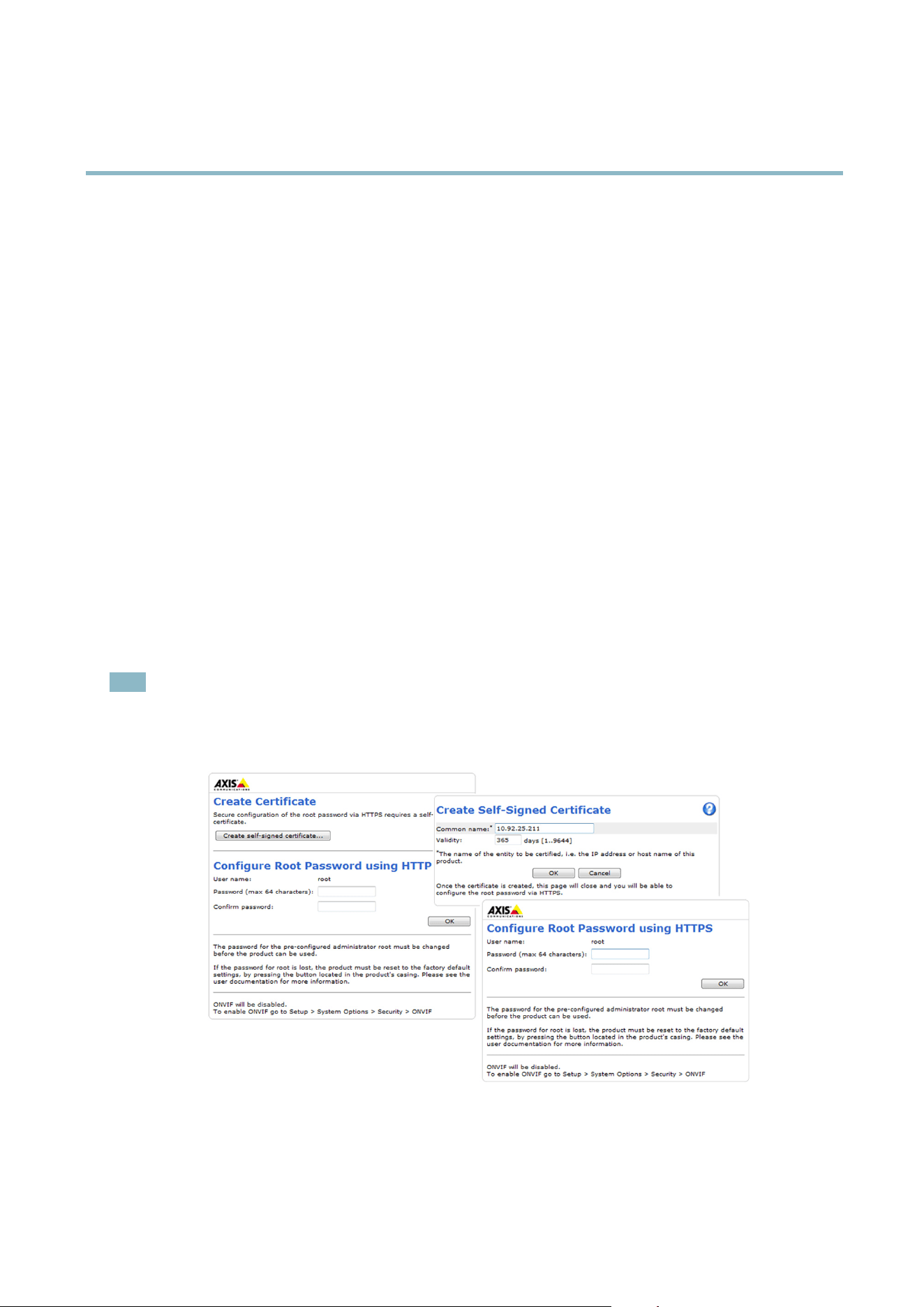
Set the Root Pa ssword
To gain access to the Axis product, you must set t he password for the default administrator user root. This is done in the Configure
Root Password dialog, which appears w hen the product is accessed for the first t ime.
To prevent network eavesdropping, the root password can be set via an encrypted HTTPS connection, which requires an HTTPS
certificate. HTTPS (Hypertext Transfer Protocol over SSL) is a protocol used to encrypt traffic between web browsers and servers. The
HTTPS certificate ensures encrypted exchange of information.
To set the password via a standard HTTP connection, enter it directly in the first dialog.
To set the password via an encrypted HTTPS connection, follow these steps:
1. Click Create self-signed certificate.
2. Provide the requested information and click OK.Thecertifica te is created and the password can now be set securely. All
traffic to and from the product is encrypted from this point on.
3. Enter a password and then re-enter to confirm the spelling. Click OK. The password has now been configured.
Note
• The default administrator user name root is permanent and cannot be deleted.
• If the password for root is lost, the product must be reset to the factory default settings. See
Reset to Factory Default
Settings on page 44
.
7

AXIS M1143–L
Accessing the Product
TheLiveViewPage
The controls and layout of the Live View page may have been customized to meet specific installation requirements a nd user
preferences. Consequently, some of the examples and functions featured here may differ from those displayed in your own Live View
page. T he following provides an overview of each available control.
Controls on the Live View Page
The Stream Profi le drop-down list allows yo u to select a customized or pre-programmed stream profile. Stream
profiles are configured under Video > Stream Profiles.See
Stream Profiles on page 15
.
Click Pulse to activate the output for a defi ne d period of time, such as switching on an external light for 20 seconds.
Click the Active/Inactive buttons to manually start and s top a connected device — e.g. switch an external light
on and off.
The Manual Trigger button is used to trigger an a ction rule from the Live View page; see . Enable this button
from Live V i ew Config > Action Buttons.
Click Snapshot to save a snapshot of the video image. Right-click the video im age to save it in JPEG form at on your
computer. This button is primarily intended for use when the A XI S M e d ia C o ntrol vie wer toolbar is not availab le.
Enable this button from Live View Config > Action Buttons.
Activate or de-activate IR illumination from Setup > Video > Camera Settings. M ove the slider to increase o r
decrease the intensity of the LEDs. Enable this button from Live View Config > Action Buttons.
AXIS Media Control viewer toolbar
The AXIS Media Control viewer toolbar is a vai lable in Internet Explorer only. See
AXIS Media Control (AMC) on page 10
for more
information. The toolbar displays the following buttons:
The Play button connects to the Axis product and starts playing a med
ia stream.
The Stop button stops the media stream.
The Snapshot button takes a s napshot of the video image. The locationwheretheimageissavedcanbespecified
in the AMC Control Panel.
Click the View Full Screen button and the
video image will fill the entire screen. Press ESC (Escape) on the computer
keyboard to cancel full screen view.
The Record button is used to record
the current video stream. The location where the recording is saved can be specified
in the AMC Control Panel.
PTZ Controls
The Live View page also displays Pan/Tilt/Zoom (PTZ) controls. The administrator can enable/disable controls for specified users under
System Options > Security > Users.
8
AXIS M1143–L
Accessing the Product
Note
These controls are available if digital PTZ is enabl ed in the selected view area, see
View Area on page 17
.
Click the Emulate joystick mode button and click in the image to move the camera view in the direction of the
mouse pointer.
Click the Center mode button and click in the image to center the camera view on that positio n. The center mode
button could also be used to zoom in on a specific are a. Click in the image and drag to draw a rectangle surrounding
theareatobemagnified. To zoom out, rotate the mouse wheel.
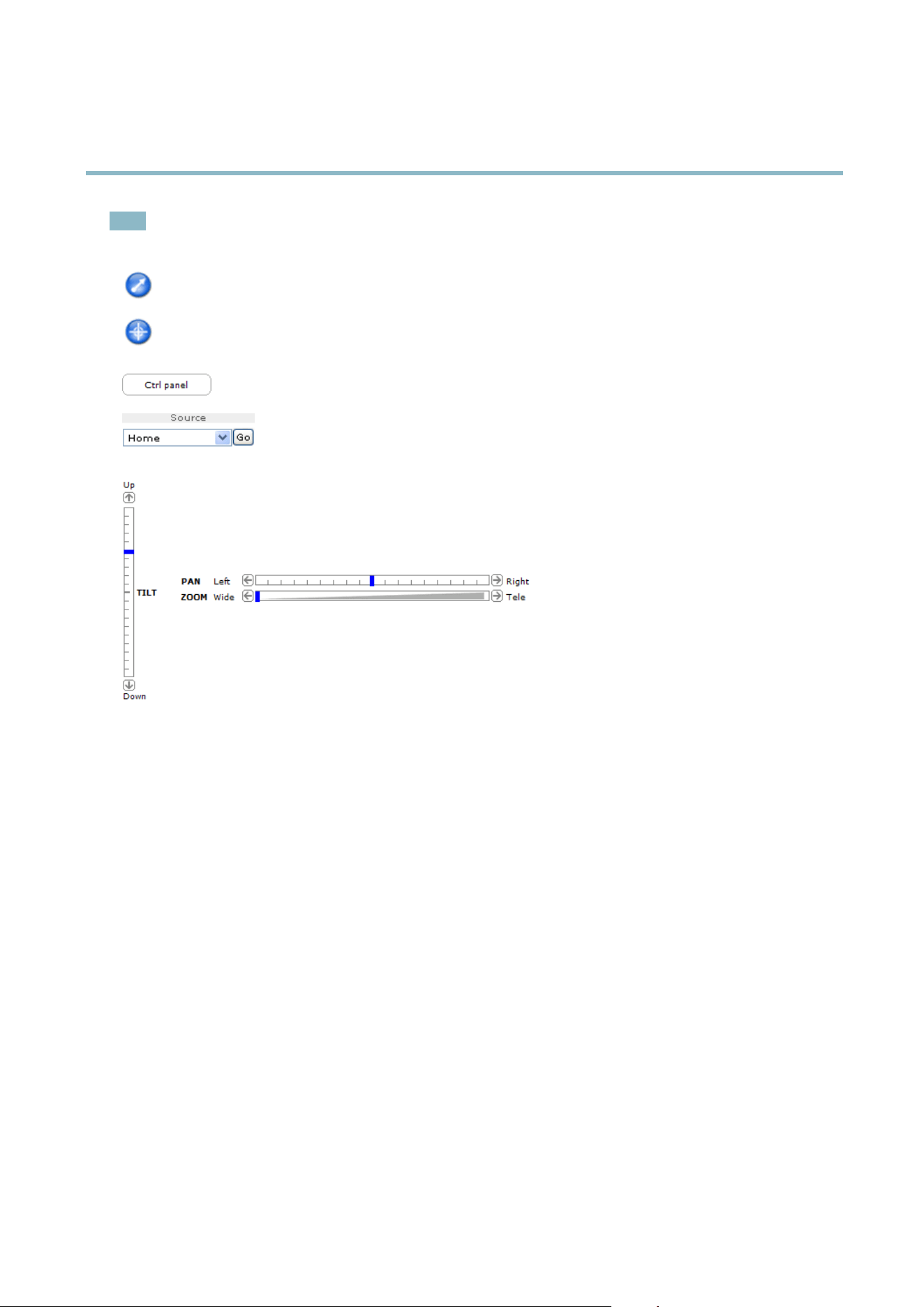
Click the Ctrl panel button to open the PTZ control panel w hich pro vides additional PTZ controls.
User-defined buttons can also appear in the Control panel. See
Controls on page 23
.
Select a PTZ preset positiontosteerthecameraviewtothesavedposition. See
Preset Positions
on p age 22
.
Pan and Tilt bars – Use the arrows to pan and tilt the camera view, or click on a position on the bar to steer the
camera view to that position.
Zoom bar – Use the a rro ws to zoom in and out, or click on a position on the bar to zoom to that position.
The PTZ controls can be disabled under PTZ > Advanced > Controls,see
Controls on page 23
.
9

AXIS M1143–L
Media Streams
Media Streams
The Axis product provides severa l vide o stream formats. Your requirements and the properties of your n e tw ork will determine the
type you use.
The Live View p ag e in the product provides access to H.264 and Motion JPEG video streams, and to the list of available stre am profiles.
Other applications and clients can access video streams directly, without going via the Live View p age.
How to Stream H.264
The video compression standard H.264 makes good use of bandwidth, and can provide high quality video streams at less than 1 Mbit/s.
Deciding which combination of protocols and methods to use depends on your viewing requirements, and on the properties of
your network. The available options in AXIS Media Control are:
Unicast RTP
This unicast method (RTP over UDP) is used
for live uni cast video, especially w hen it is
important to always have an up-to-date video
stream, even if some images are dropped.
RTP over RTSP
This unicast method (RTP tunneled over RTSP)
is useful as it is relatively simple to configure
firewallstoallowRTSPtraffic.
RTP over RTSP over HTTP
This unicast method can be used to traverse
firewalls. Firewalls are commonly configured to
allow the HTTP protocol, thus allowing RTP to
be tunneled.
Unicasting is used for video-on-demand
transmission so that there is no video traffic
on the network until a client connects and
requests the stream.
Note that there are a maximum of 20
simultaneous unicast connections.
Multicast RTP
This method (RTP over UDP) should be used for liv e m ulticast video. The video stream is always
up-to-date, even if some im ages are dropped.
Multicasting provides the m ost efficient usage of bandwidth when there are large numbers of
clients viewing simultaneously. A multicast cannot however, pass a network router unless the
router is configured to allow this. It is not possible to multicast over the Internet, for example.
Note a lso that all multicast viewers c ount as one unicast viewer in the maximum total of 20
simultaneous connections.
AXIS Media Control negotiates with the Axis product to determine the transport protocol to use. The order of priority, listed in the
AMC Control Panel, can be c hang ed and the options disabled, to suit specific requirements.
Note
H.264 is licensed technology. The Axis product includes one H.264 viewing client licens e. Installing ad ditional unlicensed
copies of the client is prohibited. To
purchase additional licen se s, contact your Axis reseller.
MJPEG
This format uses st anda rd JPEG still ima ges f o r the video stream. These images are then displayedandupdatedataratesufficient
to create a stream that shows constantly updated motion.
The Motion JPEG stream uses considerable amounts of bandwidth, but provides excellent image qualityandaccesstoeveryimage
contained in the stream. The recommended method of accessing Motion JPEG live vid eo from the Axis product is to use the AXIS
Media C ontrol in Internet Explorer in Windows.
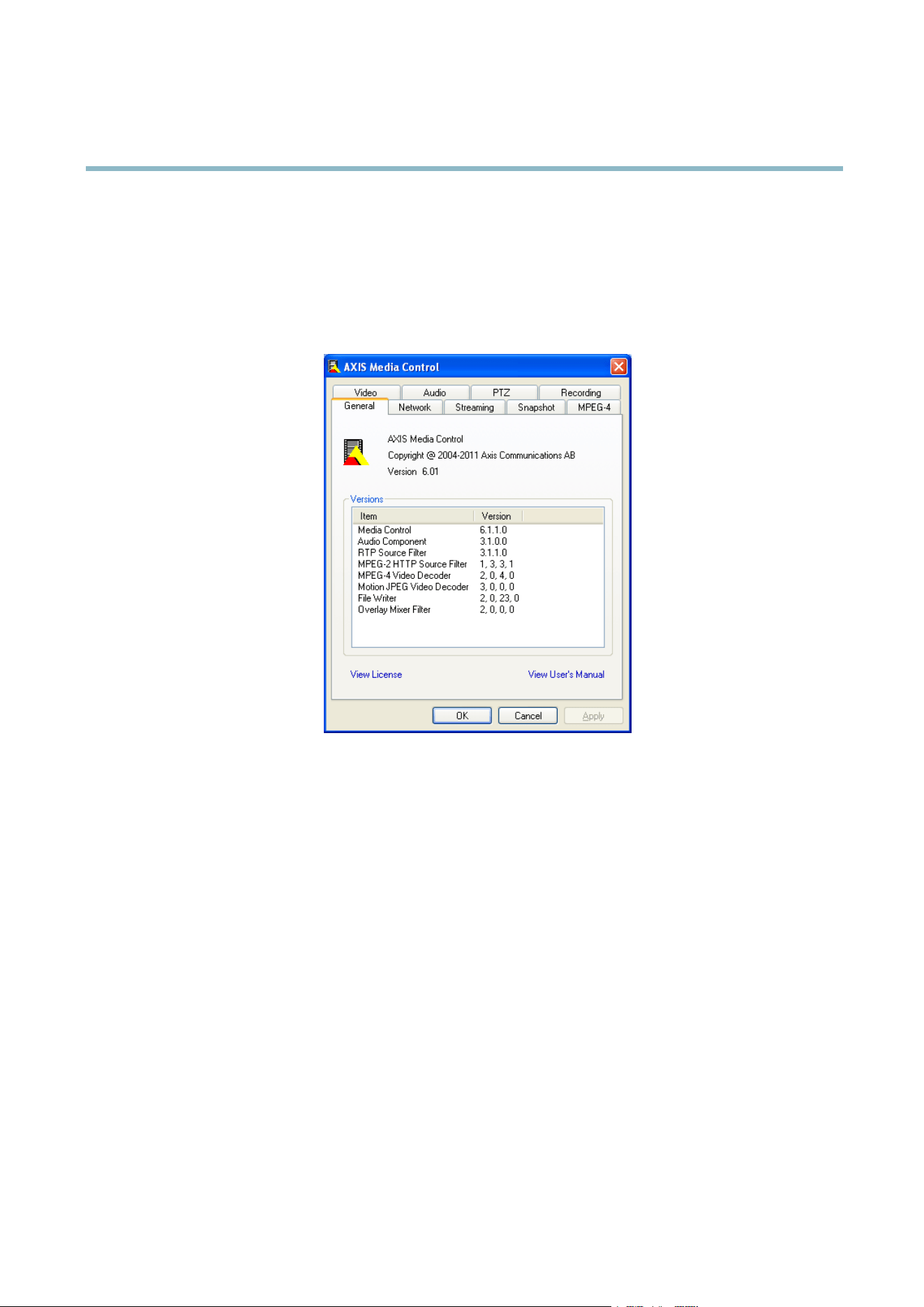
AXIS Media Control (AMC)
AXIS Media Control (AMC) in Internet Explorer in Windows is the recom m e nded method of accessing live video from the Axis product.
10
AXIS M1143–L
Media Streams
TheAMCControlPanelcanbeusedtoconfigure v a rious video settin g s. Please see the AXIS Media Control User’s Manual for more
information.
The AMC Control Panel is autom atically installed on first use, after which it can be configured. Open the AMC Control Panel from:
• Windows Control Panel (from the Start menu)
• Alternatively, right-click the video im age in Interne t Explorer an d click Settings.
Alternative Methods of Accessing the Video Stream
You can also access vide o and image s from the Axis product in the following ways:
• Motion JPEG server push (if supported by the client, Firefox, for example). This option maintains an op en HTTP connection
to the brow s er and send s data as and when required, for as long as required.
• Still JPEG images in a browser.Enterthepathhttp://<ip>/axis-cgi/jpg/image.cgi
• Windows M edia Player. This requires AXIS M edia Control and the H.264 decoder to be installed. The following paths
can be used:
- Unicast via RTP : axrtpu://<ip>/axis-media/media.amp
- Unicast via RTSP: axrtsp://<ip>/axis-media/media.amp
- Unicast via RTSP, tunneled via HTTP: axrtsphttp://<ip>/axis-media/media.amp
-Multicast:axrtpm://<ip>/axis-media/media.amp
• QuickTime
TM
. The follo wing paths can be used:
- rtsp://<ip>/axis-media/media.amp
- rtsp://<ip>/axis-media/media.3gp
11

AXIS M1143–L
Media Streams
Note
• <ip>= IP addess
• The Axis product supports QuickTime 6.5.1 and later.
• Q uickTime adds latency to the video stream.
• It may be possible to use other players to view the H.264 stream using the paths above, although Axis does not guarantee
this.
12

AXIS M1143–L
Setting Up the Product
Setting Up the P roduct
The Axis p roduct can be configured by users with administrator or operator rights. To open the product’s Setup pages, click Setup in
the top right-hand corner of the Live View page.
• Administrators have unrestricted access to all settings.
• Operators have access to all settings except System Options
See also the online help .
Basic Setup
Basic Setup provides shortcuts to the settings thatshouldbemadebeforeusingtheAxisproduct:
1. Users. See
page 33
.
2. TCP/IP. See
page 37
.
3. Date & Time. See
page 36
.
4. Video Stream. See
page 14
.
5. Focus. See
The Basic Setup menu can be disabled from System Options > Security > Users.
13

AXIS M1143–L
Setting Up the Product
Video
It is possible to configure the following video features in your Axis product:
• Video stream. See
page 14
.
•Streamprofiles. See
page 15
.
• Camera settings. See
page 16
.
•Viewarea.See
page 17
.
• Overlay image. See
page 17
.
•Privacymask.See
page 18
.
Video Stream
You can define the following video stream settings from Video > Video Stream:
•Image.See
page 15
.
• H.264. See
page 15
.
Pixel Counter
The pixel counter shows the number of pixels in an area of the im age. The pixel counter is useful in situations where there is a
requirement that the image is a certain size , for e xa m p le in face recogn ition.
The pixel counter can be accessed from:
• Video > Video Stream.UnderPreview,clickOpen and select the Show pixel counter option to enable the rectangle in
the image. Use the mouse to move and resize the rectangle, or enter the number of pixels in the Width and Height
fields and click Apply.
• The Live View page in Internet Ex plor er in Windows . Ri ght-click in the im ag e and select Pixel counter.Usethemouse
to move and resize the rectangle.
14

AXIS M1143–L
Setting Up the Product
Image
The default image settings can be configured under Video> Video Stream. Select the Im age tab.
The following settings are available:
• Resolution. Select the default resolution.
• Compression. The compression lev el affects the image quality, bandwidth and file size of saved images; the lower the
compression, the higher the image quality with higher bandwidth requirements and larger file sizes.
• Rotate image. If required, the image can be rotated.
• Mirror. If r equired, the image can be mirrored.
• Maximum frame rate. To avoid bandwidth problems, the frame rate allowed to each v ie we r ca n be limited.
• Overlay settings.See
Overlay o n page 17
.
Click Save to apply the new settings.
H.264
H.264, also known as MPEG-4 Part 10/AVC, is a video compression standard that provides high q uality video streams at low bit rates.
An H.264 video stream consists of different types of frames such as I-frames and P-frames. An I-frame is a c om ple te image whe reas
P-frames only contain the differences from previous frames.
The GOV length is the number of frames between two consecutive I-frames. Increasing the GOV length may save considerably on
bandwidth requirements in some cases, but may also have an adverse affect on image q uality.
The Axis pro duct supports two H.264 profiles.TheMainprofile provides higher compression than the Baseline pro file with the same
video quality, but requires m ore processing power to decode.
ThebitratecanbesetasVariable Bit Rate (VBR) or Constant Bit Rate (CBR ). VBR adjusts the bit rate according to the image
complexity, using up more bandwidth for increased activity in the i
mage, and less for lower image activity. CB R allows you to set a
fixed Target bit rate that consumes a predictable amount of bandwidth. As the bit rate would usually need to increase for increased
image activity, but in this case cannot, frame rate and image qualityareaffectednegatively. Topartly compensate for this, it is
possible to prioritize either frame rate or image quality. N
ot setting a priority means that frame rate and image quality are equally
affected. You must save you r settin g s before they ca n take effec t.
The current bit rate can be set to a ppear as text overlay. To do this, select the Include text check box option under Overlay
Settings and enter the m odifier #b in the field.
MJPEG
Sometimes the image size is
large due to low light or complex scenery. Ad justing the maximum frame size helps to control the
bandwidth and storage used by the Motion JPEG video stream i n these situations. Setting the frame size to the Default setting
provides consistently good image quality at the expense of increased bandwidth and storage usage in lo w light. Limiting the frame
size optimizes b
andwidth and storage usage, but may give poor image quality. To prevent increased bandwidth and storage usage,
the ma ximum fram e size should be set to an optimal value.
Stream Profiles
Astreamprofile is a s et of pre-configured stream settings including resolution, compression, frame rate and overlay settings.
Stream profiles c a n be used:
• When setting up recording using action rules, see
Events on p age 27
.
• When setting up a continuous recording, see
Continuous Recording on page 31
.
• In the Live View page — select the stream profile from the Stream profile drop-down list.
15

AXIS M1143–L
Setting Up the Product
Four pre-programmed stream profi l es are availab le for quick set up. Each pre-progr am m e d profile has a des criptive nam e, indicating
its purpose. If required, the pre-programmed s tream profiles can be modified and new customized stream profiles can be created.
To create a new profile or modify an existing profile, go to Setup > Video > Stream Profiles.
To select a default s tre am profile for the Live View page, go to Setup > Live View Config.
Camera Settings
The Video > Camera Settings page provides access to advanced image settings for the Axis product.
Image Appearance
Increasing the Color level increases the color saturation. The value 100 gives m aximum color saturation. The value 0 gives a
black and white image.
The image Brightness can be adjusted in the range 0–100, where a higher value produces a brighter image.
Increasing the Sharpness can increase bandwidth usag e . A sharper image might increase image noise especia lly in low light
conditions. A lower setting reduces image noise, but the whole image will appear less sharp.
The Contrast changes the re lati ve difference betwee n lig ht an d dark. It can be adjusted using the slidebar.
White Balance
White balance is used to m ake colors in the image appear the same regardless of the color tem per ature of the light source. The Axis
product can be set to automatically identify the light source and compensate for its color. Alternatively, select the type of light
source from the drop -dow n list. For a description of each available setting, see the online help
.
Exposure Settings
Configure the exposure s ettings to s uit the image quality requirements in relation
to lighting, frame rate and bandwidth
considerations.
Exposure value - Click in the b ar to fine-tune the exposure.
Enable Backlight compensation - Enable this option if a bright spot of light, for example a light bulb, causes other areas in
the image to appear too dark.
Exposure priority - When Motion is prioritized and maximum Shutter time is set t o a small value, motion b lur in the image is
minimized. This ca n be useful for reco
gnition of mo ving objects such as people and vehicles. However, prioritizing motion may cause
an increase in image noise, especially in low light situations. W he n Low noise is prioritized and Gain is set to a small value, image
noise is minimized. The file size is reduced, which can be useful if storage space or bandwidth is limited. However, prioritizing low
noise may resu lt in a ve ry dark im
age, especially in low light situations.
Built-in IR Illuminations LEDs
CAUTION
Do not look directly into the IR LED at short distance. Since the IR light provided from the IR LED is powerful light outside of
the visible rang
e, please use the camera to check if IR light is activated or not.
The IR illumination can be activated or de-activated, and its intensity can be increased or decreased by moving the slide r, fro m the
product’s Live View page. Other settings can be d efine d from Setup > Video > Camera Settings.
De-select the Enable IR illumination option to disable IR il lum ina ti on altogether. If you disable the Synchronize IR illumination
with day/night option, IR illumination will not be synchronized with day/night changes. To configure IR illumination click Edit .
The IR Illumination window displays the approxim ate area the IR light will illuminate given the current settings. The default IR
illumination zoom is set at 1. If the camera’s zoom is adjusted to a different value , move the Angle of illumination slider to the same
value, for optimal IR illumination in the IR Light window (Camera Settings> IR Illumination> Edit) in the camera’s GUI.
16

AXIS M1143–L
Setting Up the Product
View Area
A vie w area is a cropped par t of the full view. The view area is treated as a video source in Live View and has its own video
stream and PTZ settin gs.
When setting up a vie w ar ea it is rec om m e nde d tha t the video stream re solutio n is the same size as or sma ller tha n the vie w area
size. Setting the video stream resolution larger than the v ie w area size implies digitally scaled up video af ter sensor capture,
requiring more bandwidth without adding image information.
To enable a view area, go to Video > Camera Settings and select Enable View Area.
To configure the view area:
1. Go to Video > View Area .
2. Select an Aspect ratio and a Video stream resolution.
3. Use the mouse to move and resize the view area.
4. Select Enable PTZ to enable digital PTZ for the view area.
5. Click Save to save the settings.
Note
The PTZ functio n ality is useful during installation of the Axis product. Use a view area to crop out a specificpartofthe
full view.
Overlay
Overlays are used to provide extra information, for example for forensic video analysis or duri n g product installation and
configuration. Overlays are s upe ri mposed over the video stream.
An overlay text can display the current da te a nd time, or a text string. W hen using a text string, modifiers can be used to display
information s uch a s the current bit rate or the current frame r ate. For inform ation about available modifi ers, see
File Naming &
Date/Time Formats
in the online help .
To enable overlays:
1. Go to Video > Video Stream and select the Image tab.
2. To include an overlay image, select Include overlay image at the coordinates. The overlay image must first be uplo aded to
the A xis product, see
Overlay Image
.
3. To include date and time, select Include date and Include time.
4. To include a text string, select Include text and enter the text in the field. Mo difier s can be used, see
File Naming &
Date/Time Formats
in the o nline he lp .
5. Select the text color, the text background color and the position of the overlay.
6. Click Save.
Tomodifythedateandtimeformat,gotoSystem Options > Date & Time.See
Date&Timeonpage36
.
Overlay Image
An overlay image is a static image superimposed over the video stream. The image, for example com pany log o, is used to provide
extra information or to mask a part of the image.
Since it is static, the position and size o f an overlay image will remain the same regardles s of resolution and digital Pan/Tilt
movements. To set up a dynamic mask, which will always mask a specified part of the monitored area, see
Privacy Mask
.
17

AXIS M1143–L
Setting Up the Product
To use an overlay image, the image must first be uploaded to the Axis product:
1. Go to Video > Overlay Image.
2. Click Brow se andbrowsetothefile.
3. Click Upload.
4. Select the image to use from the Use overlay image list.
5. Click Save.
To display the overlay image:
1. Go to Video > Video Stream and select the Im a g e tab.
2. Under Overlay Settings,selectInclude overlay image at the coordinates and enter the X and Y coordinates.
3. Click Save.
For information about supported image formats, see the online help
.
Privacy Mask
A privacy mask is an area of so lid color that prohibits us e rs from viewing parts of the monitored area. Privacy masks canno t b e
bypassed via the VAPIX® Application P ro gramming Inte rfa ce (API).
The Privacy Mask List (Video > Privacy Mask) shows all the masks that are currently configured in the Axis product and indicates
if they are enabled.
You can add a new mask, re-size the mask with the mouse, choose a color for the mask, and give the mask a name.
For m ore information, see the online help
Important
Adding many p rivacy masks may affect the product’s performance.
18

AXIS M1143–L
Live View Config
Live View Con fig
You can customize the Live View page and alter it to suit your requirements. It is possible to define the following features of
theLiveViewpage.
•StreamProfile. S ee
page 15
.
• Default Viewer for Browser. See
page 19
.
• Viewer Settings. See
page 20
.
• Action Buttons. These are the buttons described in
Controls on the Live View Page on page 8
.
•UserDefined Links. See
page 20
.
• Output B uttons. See
page 20
.
Default Viewer for Browsers
From Live View Config > Default Viewer se le ct the default method for viewing video images in your browser. The product attempts
to show the video images in the selected video f orm at and v ie we r. If this is not possible, the product overrides the settings and
selects the best available comb ination.
19

AXIS M1143–L
Live View Config
Browser Viewer Description
AMC
Recommended viewer in Internet Explo rer (H.264/Motion JPEG).
QuickTime
H.264.
Java applet
A slower imaging alternative to AMC (Motion JPE G ) . R equires one of the
following installed on the client:
• JVM (J2SE) 1.4.2 or hig her.
• JRE (J2SE) 5.0 or h igher.
Windows Internet Explorer
Still image Displays still images only. Click the Refresh button in your brow se r to view a
new image.
Server Push
Recommended viewer for other browsers (M otion JPEG).
QuickTime
H.264.
Java applet
A slower imaging alternative to Serve r Push (Motion JPEG only).
Other browsers
Still image Displays still images only. Click the Refresh button in your brow se r to view a
new image.
For more inform a tion, please s ee the online help .
Viewer Settings
To co n figure options for the vie we r, go to Live View Config > Viewer Settings.
•SelectShow viewer toolbar to display the AXIS Media Control (AMC) or the QuickTim e viewer toolbar under the video
image in your browser.
• H.264 decoder installation. The administrator can d isable installation of the H.264 deco der included with AXIS Media
Control. This is used to prevent installation of unlicensed copies. Further decoder licenses can be purcha se d from your
Axis res elle r.
•SelectShow crosshair in PTZ joystick mode to ena ble a cross that will indicate the center of the i mage in PTZ joystick mode.
•SelectUse PTZ joystick mode as default to enable joystick mode. The mode can be changed temporarily from the PTZ
control panel.
•SelectEnable recording button to enable recording from the Live View page. This button is available when using
the AMC viewer. The record ings are saved to the location specified in the AMC Control Panel. See
AXIS Media Control
(AMC) on page 10
.
User Defined Links
To display user-defined links in the Live View page, select the Show custom link option, give the link a n ame and then enter the URL
to link to. W hen defining a web link do not remove the 'http://' from the URL address. Custom links can be used to run scripts or
activate external devices connected to the product, or they can link to a web p age . Custom links defined as c gi links w ill run the
script in the b ackground, in a hidden frame. Defining the link as a web link will open the link in a new window.
Output Buttons
External I/O devices connected to the Axis product’s output ports can be controlled directly from the Live View p age.
To display output buttons in the Live V ie w pag e:
1. Go to Setup > Live View Config.
2. Under Output Buttons, select the type of control to use:
- Pulse activates the output for a defined perio d of time. The pulse time can be set from 1/100 second to 60
seconds.
20

AXIS M1143–L
PTZ (Pan Tilt Zoom)
PTZ (Pan Tilt Zoom )
The PTZ me nu is available if digital PTZ (pa n, tilt and zoom) is enabl ed in the selected view area. For more information on view areas,
see
View Area on page 17
.
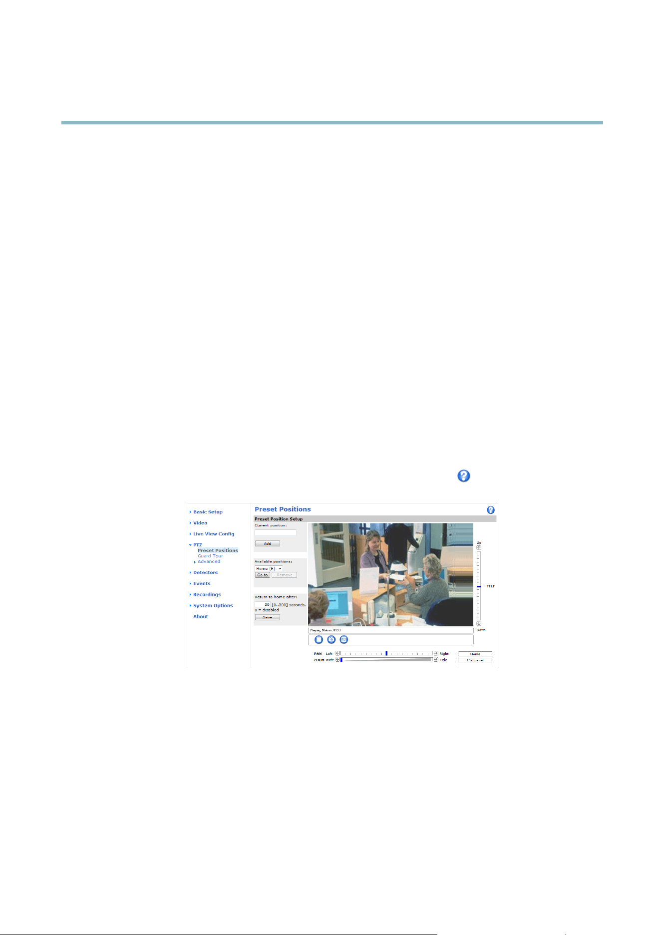
Preset Positions
A preset position is a predefined view that can be used to quickly s teer the camera to a specific location. Preset positions can
be accessed in several w ays:
• By selecting the preset from the Preset positions drop-down list in the Live View Page.
• When setting up action rules. See
page 27
.
To add a preset position:
1. Go to PTZ > Preset Positions.
2. Use the pan, tilt and zoom controls to steer the camera view to the desired position.
3. Enter a descriptive name in the Current position field.
The product can be configured to return to the Home position when the PTZ functionality has been inactive for a spec ifi ed length
of time. Enter the length of time in the field and click Save. Set the time to z er o to prevent the p roduct from automatica lly
returning to the Home position.
To include the preset position name in the overlay text, go to Video,selectInclude ove rlay text and enter the modifier #P in the field.
For more information about modifiers, see
File Naming & Date/Time Formats
in th
eonlinehelp
.
Guard Tour
A guard tour displays the video st re am from different preset po sitions, one-by-one, in a predetermined order or at random and for
configurable time periods. The enabled guard tour will keep running after the user has logged off or closed the browser.
Toaddaguardtour:
1. Go to PTZ>GuardTourand click Add.
2. Enter a descriptive n ame.
3. Specify the pause length between runs.
4. Select an available prese t position and click Apply.
22

AXIS M1143–L
PTZ (Pan Tilt Zoom)
5. Specify the View Time in seconds or minutes.
6. Specify the View Order or select the Random view order option.
7. Click Save.
To mo dify or remove guard tours, go to PTZ>GuardTour, select the guard tour in the Guard T our List and click Modify/Remove.
For m ore information see the online help
.
Advanced
Controls
Panel Shortcut Command Buttons can be co nfig u red to provide direct access to comm ands issued via the VAPIX® Application
Programming Interface. The buttons will be displayed in the PTZ control panel, which is available in the Live View page through
the Ctrl panel button, see
page 8
.
23

AXIS M1143–L
Detectors
Detectors
Camera Tampering
Camera Ta m per ing can genera te an alarm whenever the camera is repositioned, or when the lens is covered, sprayed or severely
defocused. To send an alarm, for example an email, an action rule must be set up.
To configure tampering:
1. Go to Detectors > Camera Tampering.
2. Set the Minim u m duration, that is, the time t hat m us t elapse before an alarm is generated. This can help prevent false
alarms for known conditions that affect the image.
3. Select Alarm for dark images if an alarm should b e gen e rate d if lights are dimmed or turned off, or if the lens is sprayed,
covered, or rendered severely out of focus.
4. Click Save.
To configure the pro duct to send an alarm when tampering occurs:
1. Go to Events > Action Rules.
2. Click Add to set up a new action r ule.
3. Enter a Name for the action r u le.
4. Under Condition,selectDetectors from the Trigger list.
5. Select Tamp erin g from the list of detectors.
6. Optionally, sele ct a schedule and set additional conditions.
7. Select the action. To send a n email, select Send Notification a
nd select a Recipient from the list of defined recipients.
Note
The While the rule is active option under Duration cannot be used with camera tampering, since camera tampering does not
have a duration and once it has been triggered it will not automatically re turn to its untriggered state.
For more information on actio ns rules, see
Events on page 27
.
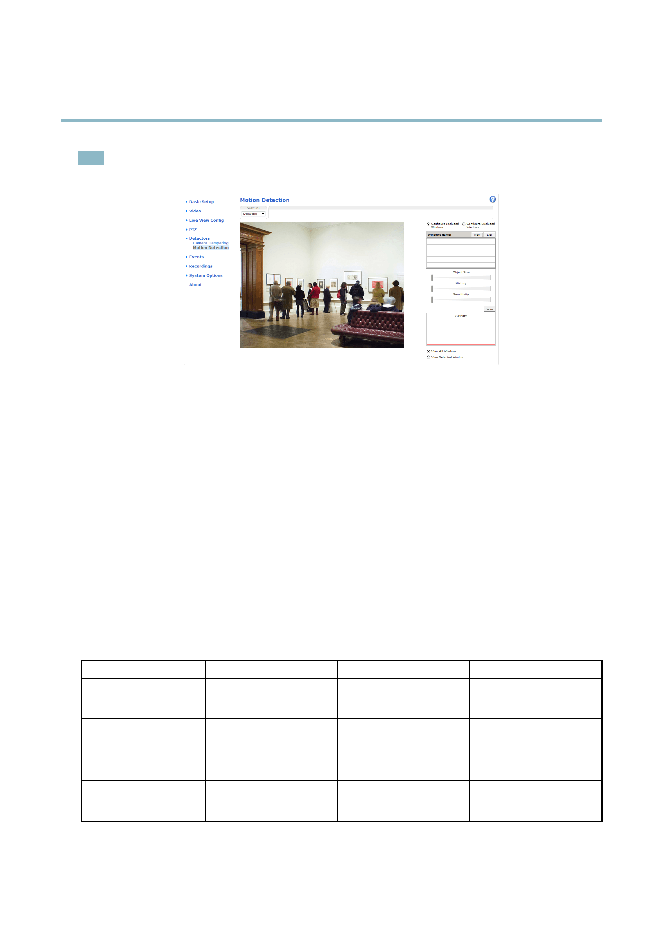
Motion Detection
Motion detection is used to generate an alarm w h enever movement starts or stops in the camera view.
Motion detection is configured by d efining up to 10 Include and Exclude windows:
• Include windows —define areas w here motion should be detected
• Exclude windows —define areas within an Include window that should be ignored (areas outside Include windows
are automatically ignored).
For instructions, see
Set Up Motion Detection Windows on page 25
.
To control the num ber of motion detection alarms, the parameters Object Size, History and Sensitivity can be a djusted. See
Motion Dete ction Parameters on page 25
.
Once motion detection windows are configured, the Axis product can be configured to perform actions w hen m o tion is detected.
Possible actions include uploading images and start recording. For more information, see
Setting Up an Action Rule on page 28
.
24
AXIS M1143–L
Detectors
Note
Using the motion detection feature may decrease the product’s overall p erf orm a nce.
Set Up Motion Detection Windows
To set up a motion detection Include Window , follow these ins tructions :
1. Go to Detectors > Motion Detection.
2. Select the Configure Included Windows option and click New. Select the new window in the list of window s and enter
a descriptive name.
3. Adjustthesize(dragthebottomright-handcorner)andthepo sitio n (click on the text at the top and dra g to the desired
position) of the window.
4. Adjust the Object Size, History and Sensitivity profile sliders (see
Motion Detection P
arameters
for details). Any detected
motion within an active window is indicated by red peaks in the Activity window.
5. Click Save.
To exclude parts of the include window, select the Configure Excluded Windows and position the exclude window within the
include window.
To delete an include or exclude window , s elect the window in the list of window s and click Del.
Motion Detection Parameters
The parameters controlling motion
detection are described in the table below:
Parameter
Object Size
History
Sensitivity
Description
Object size rela tiv
etowindow
size.
Object memory lengt
h.
Difference in lumi nance
between background and
object.
High level (100%)
Only very large objects trigger
motion detection.
An object tha
t appears in
the window triggers motion
detection for a long time
before
it is considered as
non-moving.
Ordinary colored objects on
ordinary backgrounds trigger
motion detection.
Medium level (50%)
A large difference in luminance
is required to trigge r m otion
detection.
25

AXIS M1143–L
Detectors
Low level (0%)
Even very small objects trigger
motion detection.
An object that appears in
the window triggers motion
detection only for a very short
time before it is conside re d as
non-moving.
Only very bright objects on
a dark background trigger
motion detection.
Recommen d ed values
5–15% 60–90% 75–95%
Default values
15% 90% 90%
Note
• To trigger on small objects or movements, use several small motion detection windows rather than one large window
and s elect a low object size.
• To avoid triggering on small objects, select a high object size.
• If no objects should appear in the Include Window , select a high history level. This w ill cause motion detectio n to
trigger as long as the object is present in the w indow .
• To only detect flashing light, select a low sensitivity. In other cases high sensitivity is recomme nded .
26

AXIS M1143–L
Events
Events
The Axis product can be configure d to perform actions whe n di ffe rent e ve nts occur, for example, start a rec ord ing w he n motion is
detected. The set of conditions that defines how and when the action is triggered is called an Action Rule.
Available Action Rule triggers and conditions include :
• Applications — use installed applications to trigger the rule , see .
• Detectors
- Day/Night Mode — trig ger the rule w hen the product switches b etw een day mode (IR cut filter on) and night
mode (IR cut filter off). This can for example be used to control an external infrared (IR) light connected
to an output port.
- Motion Detection — trigger the rule when motion is detected, see
Motion Detection on pa ge 24
.
- Tampering — trigger the rule when tampering is detected, see
Camera Tampering on page 24
.
• Hardware
- Network — trigger the rule if network connection is lost o r restored. This can for example be used to start
recording to the SD card.
- Temperature — trigger the rule if the temperature f alls outside or inside the operating range of the product. This
canforexamplebeusedtosendmaintenancenotifications.
• Input Signal
- Digital Input Port — trig ger the rule when an I/O port receives a signal from a connected device, see
I/O
Ports on page 42
.
- Manual Trigger — trigger the rule using the Manual Trigger button in the Live View page, see
Controls on
theLiveViewPageonpage 8
. This can for example be used to validat
e actions during product installation
and configuration.
• PTZ
- Moving — trigger the rule when the camera v iew moves due to a PTZ operation. This can for example be used
as an additi onal condition to prevent an action rule triggered by motion detectio n to record video while the
camera view m oves due to a PTZ op
eration.
- Preset Reached —trigger
therulewhenthecamerastopsatapresetposition.Thiscanbeforexamplebeused
with the Send Images action to upload images from the preset position.
• Storage
- Available — trigger the rule when the storage device is unmounted or removed. This can for example be
used to send maintenance no tifications.
- Full — trigger the rule when the s torag e device is full. Under norma l operation, the olde st r ecor dings will be
o
verwritten to prevent the storage device fr om becoming full.
- Locked — trigger the rule if the storage device is locked (write protected).
• System
- System Initializing — trigge r the rule when the p roduct is being started. Thi s can for example be used to send a
notification when the pro duct restarts.
• Time
27

AXIS M1143–L
Events
- Recurrence — trigger the rule periodically, see
Recurrences on page 29
. This can for example be used to upload
an image eve ry 5 minutes.
- Use Schedule — trigger the rule according to the se lected sc hedule, see
Schedules on page 29
.
Available actions include:
• IR light — activate/de-activate IR light.
• Output Port — activate an I/O port to control an external device.
• PTZ Control
- Preset Position — go to a preset position.
• Record Video — record video to a selected storage.
• Send Images —sendimagestoarecipient.
• Send Notifications —sendanotification m essage to a recipient.
• Status LED — flash the LED indicator. This c an fo r example be used to validate triggers such as motion detection during
product installation a nd configuration.
Setting Up an Action Rule
An action rule defines the conditio ns that must be met for the product to perform an action, f or example record video or send email
notifications. If mu ltiple conditions ar e defined, all must be met to trigger the action.
The following example describes how to set up an action rule to record video to a network share if there is movement in the
camera’s field of view.
Set up motion detection and a dd a network share:
1. Go to Detectors > Motion Detection and configure a mo tion detection w indow, see
page 25
2. Go to System Options > Storage and set up the network share, see
page 42
.
Set up the action rule:
1. Go to Events > Action Rules and click Add.
2. Select Enable rule and enter a descriptive name for the rule.
3. Select Detectors from the Trigger drop-d own list.
4. Select M otion Detection from the drop-down list. Select the motion detection window to use.
5. Optionally, select a Schedule and Additional conditions,seebelow.
6. Under Actions, select Record Video from the Type drop-down list.
7. Select a Stream profile and configure the Duration settings as described below .
8. Select Network Share from the Storage drop-down list.
To add additional criteria, s e lect the Additional conditions option and add additional triggers. To prevent an action from being
triggered repeatedly, a Wait at least time can b e set. Enter the time in hours, minutes and seconds, during w hich the trigger
should be ignore d before the action rule ca n be activated again.
The recording Duration of some actions can be set to include time immediately before and after the event. Select Pre-trigger time
and/or Post-trigger time and enter the number of seconds. When W hile the rule is active is enabled and the action is triggered
again during the post-trigger time, the recording time will be extended w ith another post-trigger time period.
28

AXIS M1143–L
Events
For m ore information, see the online help .
Recipients
Recipients receive media fi les and notification m e ss age s. The fo llow ing r ecipi ents are available:
Recipient Use with action
Email
Send Images
Send Notification
FTP
Send Images
HTTP
Send Images
Send Notification
Network Share Send Images
TCP Send Notification
Note
A network share can also be used as a storage device for recorded video. Go to System Options > Storage to configure a
network share before setting up a continuous recording or an a ction rule to record video. See
Storage on page 41
for more
information about stora ge devices.
To add a recipient:
1. Go to Events > Recipients and click Add.
2. Enter a descriptive n ame.
3. Select a recipient Type.
4. Enter the information needed for the recipient type.
5. Click Test to test the connection to the recipient.
6. Click OK.
Schedules
Schedules can be used as action rule triggers or as additional conditions, for example to record video if motion is detected outside
office hours. Use one of the predefined schedules or create a new schedule as described below .
To create a new schedule:
1. Go to Events > Schedules and click Add.
2. Enter a descriptive name and the informatio n needed for a daily, weekly, monthly or yea rly s ched ule.
3. Click OK.
To use the schedule in an Action Rule, select the schedule from the Schedule drop-down list i n the Action Rule Setup page.
Recurrences
Recurrences are use d to trigger Action Rules repeatedly, for ex am ple every 5 m inutes or every hour.
To set up a recurrence:
29

AXIS M1143–L
Events
1. Go to Events > Recurrences and click Add.
2. Enter a descriptive name and recurrence pattern.
3. Click OK.
To use the recurrence in a n Action Rule, first se lect Time from the Trigger drop-down list in the Action Rule Setup page and
then select the recurrence from the second drop-down list.
To modify or remove recurrences , sele ct the recurr ence in the Recurrences List and click Modify or Remove.
30

AXIS M1143–L
Recordings
Recordings
TheAxisproductcanbeconfigured to record video continuously or according to an action rule:
• To start a continuous recording, see
page 31
.
• To set up ac tion rules, see
page 28
.
• To access recordings, see
Recording List on pag e 31
.
•Toconfigure camera controlled storage, see
Storage on page 41
.
Recording List
Recorded videos are listed on the Recordings > List page. The list shows each recording’s start date and time, duration and the
event that triggered the recordi ng.
To play or download a recording, follow these steps:
1. Go to Recordings > List.
2. Use the filter to narrow the lis t of recordings. Enter the desired filter criteria and click Filter. Some filters may take
a long time to complete.
3. Select the recording.
4. Click Play to play the recording, or click Download to download the recording.
Multiple recordings can be downloaded at the sam e time. Select the r ecor dings and click Download. The downloaded file is a zip file
containing a minimum of three files, of which the Matroska (mkv) filesaretheactualrecordings.The recordings are tim e-stamped
with the date and time they w ere dow nloaded (tha t is, not the date the
recordings were made).
Note
To play record ings in W indow s Media Player, AXIS Matroska File Splitter must be installed. AXIS Matroska File Splitter
can be downloaded f rom www.axis.com/techsup/software
For detailed r ecor ding and video information, select a recording and click Properties.
To remove a recording, select the r ecord ing and click Remove.
Continuous Recording
TheAxisproductcanbeconfigured to continuously save video to a storage device. See
Storage on page 41
for more information
about storage devices. To prevent the d isk from becoming full, it is recommended to configure the dis k to automatica lly remove
old recordings.
To start a continuous recording, follow these steps:
1. Go to Recordings > Continuous.
2. Select Enabled.
3. Select type of storage device from the Disk list.
4. Select a Stream profile to use for continuous recordings.
5. Click Save to save and start the recording.
31

AXIS M1143–L
Recordings
Note
If a new stream profile is selected while a recording is ongoing, the recording will be stopped a nd saved in the recording list
and a new recording with the new stream profile will start. All previous continuous recordings will remain in the recording
list until they are removed manually or through autom a tic removal of old reco rdings .
32

AXIS M1143–L
System Options
System Options
Security
Users
User access control is enabled by default and can be configured under System O ptions > Security > Users. An administrator can
set up other users by giving them user names and passwords. It is also possible to allow anonymous viewer login, which m eans
that anybody may access the Live View page .
The use r list displays authorize d users and u se r groups (access l evels):
Viewer - Access to the Live View page
Operator - Access to the Live View page and to all settings except System Options
Administrator - Unrestricted access to all settings; can add, modify and remove other users.
Under HTTP/RTSPPasswordSettings, select the type of password to allow. You may need to allow unencrypted passwords if there
are viewing clients that do not support encryption, or if you upgraded the firmware and existing clients support encryption but need
to log in again and be c onfiguredtousethisfunctionality.
Under User Settings, select the Enable anonymous viewer login option to allow anonymous users access to the Live V iew page.
Select the Enable anonymous PTZ control login to allow anonymous users access to the PTZ controls.
Deselect the Enable Basic Setup option to hide the Basic S etup menu. Basic Setup provides quick access to settings that s hould be
made b efo re using the Axis product.
ONVIF
ONVIF (Op en Network Video Interface Forum) is a global interfa ce standard that makes it eas ie r for end users, integrators, consultants ,
and manufactur ers to take advantage of the possibilities of fered by netw ork video technology. ONVIF enab les interoperablity between
different vendor products, increased flexibility, red
uced cost and future-proof systems.
By creating a user you automaticall
y e nable ONVIF communication. Use the user name and p assword with all ONVIF communication
with the product. For more information see www.onvif.org
IP Address Filter
IP address filtering is enabled on the System Options > Security > IP Address Filter page. Once enabled, the listed IP address are
allowed or denied acces
s to the Axis product. Select Allow or Deny from the list and click Apply to enable IP address filtering.
The administr
ator can add up to 256 IP address entries to the list (a single entry can contain multiple IP addresses).
HTTPS
The Axis product supports encrypted browsing using HTTPS. This is configured on the System O ptions > Security > HTTPS page.
A self-sig n ed cer tificate can be used until a Certificate Authority-issued certificate has been obtained. Click Create self-signed
certificate to install a self-signed ce rtificate. Although self-signed certificates are free and offer some protection, true security is only
implemented after the installation of a signed certificate issu ed by a Certificate Authority.
To obtain a s igned certificate from an issuing Certificate Authority, click Create Certificate Request. When the signed certificate
is returned, c lick Install signed c ertificate to import the certificate. The properties of any certificate request currently resident in
the product or installed can be viewed by clicking Properties.
To enable HTTPS in the Axis product, the HTTPS Connection Policy must be set for each user group.
For m ore information, see the online help
.
33

AXIS M1143–L
System Options
HTTPS
HTTPS (HyperTe xt Transfer Protocol over Se c ure Socket Layer, or HTTP over SSL) is a web protocol providing encrypted browsing.
HTTPS can also be used by users and clients to verify that the correct device is being accessed. The security le vel provided by
HTTPS is considered adequate for most comm ercial exchanges.
The Axis product can be configur ed to require HTTPS when users from d iffe re nt user groups (administrator, operator, viewer) connect.
To use HTTPS, an HTTPS certificate must first be installed. Go to System Options > Security > Certificates to install and manage
certificates. See
Certificates on page 35
.
To enable H TTPS on the Axis product:
1. Go to System Options > Security > HTTPS
2. Select an HTTPS certificate from the list of installed certificates.
3. Optionally, click Ciphers and select the encryption algorithms to use for SSL.
4. Set the HTTPS Connection Policy forthedifferentusergroups.
5. Click Save to enab le the settings.
To access the Axis product via the desired protocol, enter https:// or http:// in the address fi eld in a browser.
The HTTPS port can be changed on the System Options > Network > TCP/IP > A dvanced page.
IEEE 802.1X
IEEE 802.1X is a standard for port-based Network A dmission Control providing secure authentication of wired and wireless ne
twork
devices. IEEE 802.1X is based on EAP (Extensible Authentication P rotocol).
To access a network protected by IEEE 802.1X, devices must authenticate themselves. The authentication is performed by a
third-party entity called an authentic ation server, typically a RADIUS server, examples of which are FreeRADIUS and Microsoft
Internet Authentication Service.
In Ax is' implem enta tion, the netw ork device and the authent
ication server authenticate themselves with the help of dig ital
certificates using EAP-TLS (Extensible Authentication Protocol - Transport Layer Security). The certificates are provided by an
Certification Authority (CA ). You need:
•aCAcertifica te to validate the identity of the authentication server
• a CA-signed c lient certificate and a private key to authenticate the network device.
To allow the network d evice to access a network protected by IEEE 802.1X:
1. Obtain a CA certificate, a client certificate and a client private key (contact your network administrator).
2. Go to Setup > System Options > Security > IEEE 802.1X and upload the CA certificate, the client certificate and the
client p
rivate key.
3. Und
er Settings, select the EAPOL version, provide your EAP identity and private key password.
4. Check the box to enable IEEE 802.1X and click Save.
34

AXIS M1143–L
System Options
Certificates
CA Certificate The CA certificate is used to va lida te the identity of the authentication s erver. Enter the path to
the certificate directly, or lo cate the file using the Browse button. Then click Upload.Toremove
acertificate , click Remove.
Client certificate
Client private key
The clie nt certificate and private key are used to authen tica te the network device. They can be
uploaded as se par ate files or in one combined file (e.g. a PFX file or a PEM file). Use the Client
private key field if uploading one combined file. For each file, enter the path to the file, or locate the
file using the Browse button. Then click Upload.Toremoveafile, click Remove.
Settings
EAPOL version
SelecttheEAPOLversion(1or2)asusedinyournetworkswitch.
EAP identity
Enter the user identity (maximum 16 characters) associated with your certificate.
Private key password
Enter the password (maximum 16 characters) for the private key.
Enable IEEE 802.1X
Check the bo x to enable the IEEE 802.1X protocol.
IEEE 802.1X
IEEE 802.1X is a standard for port-based Network Admission Control providing secure authentication of wired and wireless network
devices. IEEE 802.1X is based on EAP (Extensible Authentication P rotocol).
To access a network protected by IEEE 802.1X, devices must be authenticated. The authentication is performed by an authentication
server, typically a RADIUS server, examples of which are FreeRADIUS and Microsoft Internet Authentication Service.
In Axis implementation, the Axis product and the authentication server identify them s el ves with digital certi fica tes using EA P-TLS
(Extensible Authentication Protocol - Transport Layer Security). The certificates ar
eprovidedbyaCerti fication Authority (CA).
You need:
•aCAcertificate to authenticate the a uthentica tion server
• a CA-signed client certificate to authenticate the A xis product.
To create and install certifi cates, go to System Options > Security > Certificates.See
Certificates on page 35
.ManyCAcertificates
are preinsta lle d.
To allow the product to access a network protected by IEEE 802.1X:
1. Go to System Options > Security > IEEE 802.1X.
2. Select a CA Ce rtificate and a Client C ertificate from the lists of installed certificates.
3. Under Settings, select the EAPOL version and provide the EAP identity associated with the client certificate.
4. Check the box to enable IEEE 802.1X and click Save.
Note
For authentication to work properly, the date and time settings in the Axis product should be synchronized with an NTP
server. See
Date & Time on page 36
.
Certificates
Certificates are used to authenticate devices o n a network. Typical a pplications includ e encrypted web brow sing (HTTPS), netw ork
protection via IEEE 802.1X and secure upload of images and notification messages for example via email. Two types of certificates
can be used with the Axis product:
Server/Client certificates - to authenticate the Axis product
35

AXIS M1143–L
System Options
CA certificates - to authenticate peer certificates, for example the certificate of an authentication server in case the Axis product is
connected to an IEEE 802.1X protected n etwork.
Note
Installed certificates, except preinstalled CA certificates, will be deleted if the product is reset to factory default. Preinstalled
CA certificates that have b ee n dele ted will be reinstalled.
A Server/Client certificate can be self-signed or issued by a Certificate Authority (CA ). A self-signed certificate offers limited
protection and can be used before a CA-issued certificate has been obtained.
To install a self-sign e d certificate:
1. Go to System Options > Security > Certificates.
2. Click Create self-signed certificate and provide the requested in forma tion.
To create a nd install a CA-signed certificate:
1. Create a self-signed certificate as described above.
2. Go to System Options > Security > Certificates.
3. Click Create certificate signing request and provide the requested information.
4. Copy the PEM-formatted request and send to the CA of your choice.
5. When the signed certificate is returned, click Install certificate and upload the certificate.
Server/Client certificate s c an be installed as Certificate from signing request or as Certificate and private key.SelectCertificate
and private key if the private key is to be u pload as a separate file or if the certificate is in PK CS#12 format.
The Axis product is shipped with several preinstalled CA certificates. If required, additional CA certificates can be installed:
1. Go to System Options > Security > Certificates
2. Click Install cer tificate and upload the certificate.
Date & T ime
The Axis product’s date and time s ettings are configured under System Options > Date & Time.
Current Server Time displays the current date and time (24h clock). The time can be d isplayed in 12h clock in the text overlay (see
below).
To change the date and time setting s, select the preferred Time mode under New Server Time:
• Synchronize with computer time sets date and time according to the computer’s clock. With this option, date and
time are set once and will not be upd ated automatically.
• Synchronize with NTP Server o btains date and time from a n NTP server. W ith this option, date and time settings are
updated continuously. F or information on NTP settings, see
NTP Configuration on page 38
.
If using a host name fo r the NTP server, a DNS server must be confi gured. See
DNS Configuration on page 38
.
• Set m anually a llow s you to manually set date a n d time.
If using an NTP server, select your Time zone from the drop-down list. If required, check Automatically adjust for daylight saving
time changes.
The Date & Time Format Used in Images is the date and time format displayed as a text overlay in the video stream. Use the
predefined formats or see
File Naming & Date/Time Formats
in the online help for information on how to create custom date and
time formats. To include date and time in the overlay text, go to Video and select Include date and Include time.
36

AXIS M1143–L
System Options
Network
Basic TCP/IP Settings
The Axis product supports IP version 4 and IP version 6. Both versions can be enabled simultaneo usly, and at least one version
must always be enabled.
Network Interface Mode
The network interface to the AXIS product can be wired or wireless. Different settings can be used for e ach n e tw o rk in te rf ace , but
only one can be used at a time. In Auto mode the product will use a wireless network unless a network cable is connected, in which
case it will use the w ired network. In Wired m ode the product will require a network cable to connect to the network.
IPv4 Address Configuration
By default, the Axis p roduct is set to use IPv4 (IP version 4) and to obtain the IP address automatically via DHCP. The IPv4 settings are
configured under System Options > Network > TCP/IP > Basic.
DHCP (Dynamic Host Configuration Protocol) allows network administrators to centrally manage and automate the assignment of
IP addresses. DHCP should only be enabled if using dynamic IP address notification, or if the DHCP can update a DNS server. It is
then possible to access the Axis product by name (host name).
If DHCP is enabled and the product cannot be accessed, run AXIS IP Utility to search the netwo rk for connected Ax is products, or reset
the product to the factory default settings (see
page 44
) and then perform the installation again.
To use a static IP address, check Use the following IP address and specify the IP address, subnet mask and d efault router.
IPv6 Address Configuration
If IPv6 (IP version 6) is enabled, the Axis product will receive an IP address according to the c onfiguration in the network router.
To enable IPv6, go to System Options > Network > TCP/IP > Basic. Other settings for IPv6 should be configured in the network router.
ARP/Ping
The IP address can be set using ARP and Ping. For instructions, see the product’s
Installation Guide .
ARP/Ping is enabled by defa u lt. To disable, uncheck t
he box under System O ptions > Network > TCP/IP > B asic.
The ARP/ P ing service is au tomatically disable
d two minutes after the product is started, or as soon as an IP address is s et. To reset the
IP address, the product must be restarted to activate ARP/Ping for an additional two minutes.
Pinging the product is still possible when this service is disabled.
AXIS Video Hosting System (AVHS)
AVHS used in conjunction
with an AVHS service, provides easy and secure Internet access to live and recorded video accessible from
any location. For more information and help to find a local AVHS Service Provider go to www.axis.com/hosting
AVHS is enabled by d efa u lt. The settings are configured under System Options > Network > TCP IP > Basic.
One-click enabled - Press the product’s control button (see
Hardware Overview on page 4
) to connect to an AVHS service over the
Internet. Once registered, Always will be enabled and the Axis product stays connected to the AVHS s ervice. If the product is not
register
ed within 24 hours from w hen the button is pressed , the product will disconnect from the AVHS service.
Alwa
ys - The Axis product will consta ntly attempt to connect to the AVHS service over the Internet. Once registered the product will
stay connected to the service. This option can be used when the product is already installed and it is not c onvenient to use the
one-click installa tion.
37

AXIS M1143–L
System Options
AXIS Internet Dynam ic DNS Service
AXIS Internet Dynamic DNS Service assigns a host name for easy ac ce s s to the product. For more information, see www.axiscam.net
To register the A xis product with AXIS Interne t Dynamic DNS Se rvice , go to System Op tions > Network > TCP/IP > Basic.Under
Services, click the AXIS Internet Dynam ic DNS Service Settings button (requires access to the Internet). The domain name currently
registered at AXIS Internet Dynamic DNS serv ice fo r the product can at any time be removed.
Advanced TCP/IP Settings
DNS Confi guration
DNS (Domain Name Service) provides the translation of host names to IP addresses. The DNS settings are configured under System
Options > Network > TCP/IP > Advanced.
Select Obtain D NS server address via DHCP to use the DNS settings provided by the DHCP server.
To make manual settings, select Use the following DNS server address and specify the following:
Domain name - Enter the domain(s) to search for the h ost name used by the Axis pro duct. Multiple domains can be separated by
semicolons. The host name is always the firstpartofafullyqualified domain name, for example, myserver is the host name in the
fully qualified domai n name myserver.mycompany.com where mycompany.com is the domain name .
Primary/Secondary DNS server - Enter the IP addresses of the primary and secondary DNS server s. The secondary DNS server is
optional a nd will be used if the primary is unavailable.
NTP Configuration
NTP (Network Time Protocol) is used to synchronize the clock times of devices in a network. The NTP settings are configured under
System Options > Network > TCP/IP > Advanced.
Select Obtain NTP server address via DHCP to use the NTP setting s provided by the DHCP server.
To m ake manual settings, select Use the following NTP server address and enter the host name or IP a ddress of the N TP server.
Host Name Configuration
The Axis product can be ac cessed using a host name instead of an IP address. The host name is usually the same as the assigned DNS
name. The host name is configured under System Options > Network > TCP/IP > A dvanced.
Select Obtain host name via IPv4 DHCP to use host name provided by the DHCP server running on IPv4.
Select Use the host name to set the host name manually.
Select Enable dynamic DNS updates to dynamically update local D N S servers whene ver the Axis prod uct’s IP address changes.
For m ore information, s
eetheonlinehelp
.
Link-Local IPv4 Address
Link-Local Address is enabled by default and assigns the Axis product an additional IP address whichcanbeusedtoaccess
the product fr
om o ther hosts on the same segment on the local network. The product can have a Link-Local IP and a static
or DHCP-supplied IP address at the same tim e .
This function can be disable d under System Options > Network > TCP/IP > Advanced.
HTTP
T
he HTTP port used by the Axis product can be changed under System Options > Network > TCP/IP > Advanced. In addition to the
default setting, w hich is 80, any port in the range 1024–65535 can be used.
38

AXIS M1143–L
System Options
HTTPS
The HTTPS port used by the Axis product can be changed under System Options > Network > TCP/IP > A dvanced. In addition to
the default setting, which is 443, any port in the range 1024–65535 can be used.
To enable HTTPS, g o to System Options > Security > HTTPS. For more information, see
page 33
.
NAT traversal (port mapping) for IPv4
A network router allows devices on a private network (LAN) to share a single connection to the Internet. This is done by forwarding
network traffic from the private network to the “outside”, that is, the Internet. Security on the private network (LAN) is increased
since m ost routers are pre-configured to stop attempts to a ccess the private network (LAN) from the public network (Internet).
Use NAT traversal w he n the Axis product is located on an intranet (LAN) and you wish to make it available from the other
(WAN) side of a NAT router. W ith NAT traversal prope rly configured, all HTTP traffic to an external H TTP port in the NA T router
isforwardedtotheproduct.
NAT tra ve rs al is configured under System Options > Network > TCP/IP > A dvanced .
Note
• F or NA T tra vers al to w ork, this mus t be supporte d by the ro uter. The router m ust also support UPnP
TM
.
• The router has many d iffere nt names: “NAT router”, “Network router”, “Internet G ateway”, ”B roa dband router”, “Broadband
sharing device” or “Home firewall” but the essential purpose of the device is the same.
Enable/Disable - When enabled, the Axis product attempts to configure port mapping in a NAT router on your network, using UPnP
TM
.
Note that UPnP
TM
must be enabled in the product (see System O ptions > Network > UPnP).
Use manua lly selected NAT router - Select this option to manually select a N AT router and enter the IP ad dress for the ro uter in
the field. If no router is specified, the pro duct automatically searches for NAT routers on yo ur network. If more than one router is
found, the default router is selected.
Alternative HTTP port - Select this option to manually define an external HTTP port. Enter the port number in the field. If no port is
entered he re , a port number is autom a t ically selected whe n NAT trave rs al is enable d.
Note
• An alternative HTTP port can be used or be active even if NAT traversal is disabled. This is useful if your NAT router does
not support UPnP and you need to manually configure p ort for wa rding in the NAT route r.
• I f you attemp t to manually enter a port that is already in use, another available port is automatically selecte d .
• When the p ort is selected automatically it is displayed in this field. To change this, enter a new port num ber and click Save.
FTP
The FTP server running in the Axis product enables upload o f new firmware, u se r applications, etc. The FTP server can be disabled
under System Op tions > Network > TCP/IP > Advanced.
Note
This FTP serve r has nothing to do with the product’s ability to transfer images via FTP to othe r locations and servers.
RTSP
The RTSP server running in the Axis product allows a connecting client to start an H.264 stream. The RTSP port number can be
changed under System Options > Network > TCP/IP > Advanced. The default port is 554.
Note
H.264 video streams will not be available if the RTSP server is disabled.
39

AXIS M1143–L
System Options
SOCKS
SOCKS is a networking proxy protocol. The Axis product can b e configured to use a SOCKS server to reach networks on the other
side of a firewall or proxy server. This functionality is useful if the A xis product is located on a local network behind a firewall, and
notifications, uploads, alarms, etc need to be sent to a destination outside the local network (for example the Internet).
SOCKS is configured under System Options > Network > SOCKS. For more informatio n, see the online help
.
QoS (Quality of Service)
QoS (Quality of Service) guarantees a certain level of a specified resource to selected traffic on a network. A QoS-aware network
prioritizes network traffic and provides a greater network reliability by controlling the amount of bandwidth an application may use.
The Q oS settings are configured under System Options > Network > Q oS . Using DSCP (Differentiated Services Co depo int) values, the
Axis product can mark the following types of traffic: live video, event/ala rm traffic and management traffic.
SMTP (email)
To send email messages from the Axis pro duct via SM TP (Simple Mail Transfer Protocol), an SMTP mail server must be set up. This
is done under System Options > Network > SMTP (email).
Enter the host names or IP addresses and port numbers for the primary and secondary mail servers in the fields provided . A From
email address is also required . If the mail server requires authentication, check Use authentication to log in to this server and enter
the necessary information.
SNMP
The Simple Network Ma nag ement P rotocol (SNMP) allows remote management of network devices. An SNM P com munity is the
group of devices and management station running SNMP. Community names are used to identify groups.
The Axis product can be configured to support SNMP on the System Options > Network > SNMP page.
Depending on the level of security req uired, select the version on SNMP to use.
SNMP v1/v2 provides the lowest level of security. The community name can be specified as a p assw ord for re ad or read/write
access to all supported SNMP devices. The default passw ord for the Read community is public and the default password for the
Write community is write.
Note
If HTTPS is enabled, SNMP v1 and SNMP v2c should be disabled.
Traps for SNMP v1/v2 are used by the Axis product to send messages to a management system on important events and status
changes. Check Enable traps and enter the IP address where the trap message should be sent a nd the Trap community that
should receive the message.
The following traps are available:
•Coldstart
•Warmstart
•Linkup
• Authentication failed
SNMP v3 provides encryption and secure passwords. To use traps with SNMP v3, an SNMP v3 management application is required.
To use SNMP v3, HTTPS must be e nab led, see
HTTPS on page 33
. To enable SNMP v3, check the box and provide the initial user
password.
40

AXIS M1143–L
System Options
Note
The initial password can only be set once. If the p assword is lo st, the Axis prod uct must be reset to factory default, see
Reset to Factory Default Settings o n page 44
.
UPnP
TM
The Axis pro duct includes support for UPnP
TM
.UPnP
TM
is enabled by default and the product is automatically detected by operating
systems and clients that support this protocol.
UPnP
TM
can be disable d under System Options > Network > UPnP
TM
.
RTP/H.264
The RTP port range and multicast settings are co nfig u red under System Options > Network > RTP.
The RTP port range defines the range of p o rts from which the video ports are automati ca lly selected. For multicas t streams, only
certain IP addresses and port numbers should be used.
Select Always Mu lticast Video to start multicast streamin g without opening an RTSP session.
Bonjour
The Axis product includes support for Bonjour. Bonjo ur is enabled by default and the produ ct is automatically detected by operating
systems and clients that support this protocol.
Bonjour can be disabled under System Options > Network > Bonjour.
Storage
SD Card
NOTICE
To prevent corruption of recordings, the SD card should always be unmounted before
it is ejected.
The Axis product supports SD cards with the fo llow ing file systems:
• ext4 — recom m e nde d due to its resilience against data loss if the card is ejected or if there is a brupt power loss. To access
data stored on the card from the Windows operating system, a third-party ext4 driver or application is required.
• vFAT — most SD cards are pre-formatted with vFAT when purchased.
If required, the SD card can be re-formatted to the desired file system . To format the SD card:
1. Insert the SD card in the SD card slot.
2. Go to System Options > Storage an d click SD Card.
3. Click Format and select the desired file system.
Note
During formatting any previous d ata stored on the disk wi ll be lost.
Mounting is done automatically when the card is inserted or whe n the product is started. A manual mount is only required if the
card has been unmounted and not ejected and re-inserted.
To unmount the SD card:
1. Go to System Options > Storage an d click SD Card.
2. Click Unmount.
41

AXIS M1143–L
System Options
3. The card can now be removed.
The SD card is managed on the System Options > Storage page. Click SD Card to o pen Storage M anagement.
If the card’s status shows as fa ile d, click Check disk to see if the problem can be found and then try Repair. T his option is only
available for S D card s with ext4. For SD cards with vFAT, use a card reader or computer to troubleshoot the card.
To avoid filling the ca rd, it is recommended to remove recordings continuously. Under Recording Settings, select Remove recordings
older than and select the number of days or weeks.
To stop writing to the card and protect recording s from being removed, select Lock under Recording Settings.
Network Share
Network share allow s you to add network storage such as a NAS (Network Attached Storage) or any server that uses C IFS (Common
Internet File System) and use them for storage of recordings.
To add a network share:
1. Go to System Options > Storage.
2. Click Network Share.
3. Enter the IP address, DNS or Bonjour name to the host server in the Host field.
4. Enter the name of the share in the Share fi el d.
5. If required, select The share requires login and enter the u se r name and password.
6. Click Connect.
To clear all recordings and data from the A xis product’s folder on the des
ignated share, click Clear under Storage Tools.
To avoid filling the share, it is recom m e nded to rem ove recordings
continuously. Under Recording Settings,selectRemove recordings
older than and select the number of days or weeks.
To stop w riting to the share and protect recordings from being removed, select Lock under Recording S ettings.
Ports & Devices
I/O Ports
The Axis product provides one input port and one output port for connection of exte rnal devices. For information on how to
connect external devices, see
Connectors on page 4
.
The I/O p orts are configured under System O ptions > Ports & Devices > I/O Ports. The ports can be given descriptive names and their
Normal st
ates can be configured as Open circuit or Grounded circuit.
Port Status
The list on the System Options > Ports & Devices > Port Status page shows the status of the product’s input and output ports.
Maintenance
The Axis product provides several maintenance functions. These are available under System Options > Maintenance.
Click Restart to perform a co rrect restart if the Axis product is not behaving as expected. This will not affect any of the current
settings.
Click Restore to reset m ost settings to the factory defau lt values. The following settings a re not affected:
42

AXIS M1143–L
System Options
• the boot pro tocol (DHCP or static)
• the static IP addr ess
• the default router
• the subnet mask
•thesystemtime
• the IEEE 802.1X settings
• the focus position
Click Default to reset all setting s, including the IP address, to the f actory default values. This button should be used with caution. The
Axis product can also be reset to factory default using the control button, see
Reset to F a c tory Default S e ttings on page 44
.
To identify the p roduct or test the Status LED, click Flash LED under Identify and specify the duration in seconds, minutes or hours.
This can be useful for identifying the p roduct am ong other products installed in the same locati on.
For information about firmware upgrade, see
Upgrading the Firmware on page 45
.
Support
Support Overview
The System Options > Support > Support Overview page provides information on troubleshooting and contact information,
should you require technical assistance.
See a lso
Troubleshooting on page 45
.
System Overview
To g et an overview of the Axis product’s status and settings, go to System Options > Support > System Overview. Information that
can be found here includes firmware version, IP address, ne
twork and security settings, event settings, image settings and recent log
items. Many of the captio ns are links to the proper Setup page.
Logs & Reports
The System Options > Support > Logs & Reports page generates logs and reports useful for system analysis and troubleshooting. If
contacting Axis Support, pleas
e provide a valid Server Report with your query.
System Log - Provides info
rmation about system events.
Access Log - Lists al
l failed attempts to access the product. The Access Log ca n also be configured to list all connections to the
product (see below).
Server Report - Provides information about the product status in a pop -up window. The Access Log is automatically included
in the Server Report.
You can view or dow nload the server report. Downloading the server report creates a .zip file that contains a complete server report
text file in U TF–8 f orm a t. Select the Include snapshot w ith default image settings option to include a snapshot of the product’s
Live View that also shows the settings specified under Video Stream>Image>Image Appearance. T he se rver report .zip file should
always be included when contacting support.
Parameter L ist - Shows the product's parameters and their current settings. This may prove useful when troubleshooting or
when contacting Axis Suppo rt.
Connection List - Lists a ll clients that are currently a c ce s sing media streams.
Crash Report - Ge nerate s an archive with de bugging inform a tion. The report takes several minutes to generate.
43

AXIS M1143–L
System Options
The log levels for the System Log and the Access Log are set under System Options > Support > Logs & Reports > Configuration.
The Access Log can be configured to list all connections to the product (select Critical, Warnings & Info). If required, a different log
level can be used wh e n sending emails.
Advanced
Scripting
Scripting allow s experienced users to customize and us e their o wn scripts.
NOTICE
Improper use may cause unexp ected behavio r and loss of contact with the Axis product.
Axis strongly recomm ends that you do not use this function unless y ou understand the consequences. Axis Support does no t provide
assistance for problems with customized scripts.
To open the Script Editor, go to System Options > Advanced > Scripting. It is recommended to create a backup file before
customizing the scripts. If a script causes problem s , reset the product to its factory de fa ult settings , se e
page 44
.
For more information, see www.axis.com/developer
File Upload
Files, for example web page s and images, can be uploaded to the Axis product and used as custom settings. To upload a file, g o
to System Options > Advanced > File Upload.
Uploaded files are accessed through http://<ip address>/local/<user>/<file name> where <user> is the
selected user group (viewer, operator or administrator) for the uploaded file.
Plain Config
Plain C on fig is for advanced users with experience of Axis product confi guration. Most parameters can be set and modified from this
page. Help is available from the standard help pages.
To open Plain Config, go to System Option s > Advan c ed > Plain Config .
Reset to Factory Default Settings
This will re se t all param ete rs , including the IP address, to the factory default settings :
1. Disconnect power from the product.
2. Press and ho ld the Control b utton and reconnect power (see
Hardware Overview on page 4
).
3. Keep the C ontrol b utton pressed for about 15 seconds until the Status indicator flashes amber.
4. Release the Control button. The process is complete after about 1 minute (when the Status indicator turns green). The
product has been reset to the factory default settings. The default IP address is 192.168.0.90
5. Re-assign the IP address.
It is also possible to reset parameters to factory default via the web interface. Go to Setup > System Options > Maintenance.
44

AXIS M1143–L
Troubleshooting
Troubleshooting
Checking the Firmware
Firmware is software that determines the functionality of network devices. One of your first actions when troubleshooting a problem
should be to check the current firmware version. The latest version m a y contain a correction that fixesyourparticularproblem.The
current firmware version in the A xis prod uct is displa yed in the page Setup > Basic Setup and in Setup > About.
Upgrading the Firmware
When you upgrade the product with the latest firmw a re fr om Axis website, the product receives the late st functiona lity available.
Always read the upgrade instructions and release notes available with each new release, before upgra ding the firmware.
To upgrade, follow these instructions:
1. Save the firmware file to your computer. The latest version of the fir m ware is available free of charge from Axis w e bsite
at www.axis.com/techsup
2. Go to Setup > System Options > Maintenance in the products web pages.
3. Under Upgrade Server, click Browse and locate the file on your co m puter . Click Upgrade.
After starting the upgrade process, a lways wait at least 5–10 minutes before restarting the product, even if you suspect the
upgrade has failed.
AXIS Camera Management can be us ed f or m ultiple upgrades. See www.axis.com for m ore information.
Note
• Your dealer reserves the right to charge for any repair attributable to faulty upgrade by the user.
•Preconfigured and customized settings are saved when the firmware i s upgraded
(providing the features are available in
the new firmware) although this is not guaranteed b y Axis Com m unicatio n s AB.
Emergency Recovery Procedure
If pow
er or network connection is lost during the upgrade, the process fails and the product becomes unresponsive. Flashing red Status
indicator indicates a failed upg rad e. To recover the pr oduct, follow the steps below. The serial number is found on the product’s label.
1. In UNIX/Linux, type the following from the command line:
arp -s <IP address> <serial number> temp
45

AXIS M1143–L
Troubleshooting
ping -s 408 <IP address>
In Windows, type the following from a command/DOS prom pt (this may require that you run the command prom pt as
an admin istra tor):
arp -s <IP address> <serial number>
ping -l 408 -t <IP address>
2. If the product does not rep ly in 30 seconds, restart it and wait for a reply. Press CTRL+C to stop Ping.
3. Open a browser and type in the product’s IP address. In the page that appears, use the Browse button to select the upgrade
file to use. Then click Load to restart the upgrade process.
4. After the upgrade is complete (1–10 minutes), the product automatically restarts and shows a steady green on the Status
indicator.
5. Reinstall the product, referring to the Installation Guide.
If the emergency recovery procedure does not get the product up and running again, contact A xis support at www.axis.com/techsup/
Symptoms, Possible Ca uses and Remedial Actions
Problems setting the IP address
When using ARP/Ping
Try the installation again. The IP address must be set within two minutes after power has been
applied to the product. Ensure the Ping length is set to 408. See the Installation Guide for
detailed instructions.
The product is located on a
different s ubnet
If the IP address intended for the product and the IP address of the computer used to access the
product are located on different subnets, you w ill not be able to set the IP address. Contact your
network administrator to obtain an IP address.
The IP address is be ing used
by another device
Disconnect the Axis product from the network. Run the Ping command (in a Command/DOS
window, type ping and the IP address of the product:
•Ifyoureceive:Reply from <IP address>: bytes=32; time=10...
this means that the IP address may already be in use by another device on the network.
Obtain a new IP address from the network administrator and reinstall the product.
•Ifyoureceive:Request timed out, this means that the IP address is available for
use with the Axis product. Check all cabling and reinstall the product.
Possible IP address c onflict
with another device on the
same subnet.
The static IP address in the Axis product is used before the DHCP server s ets a dynamic ad dre ss .
This means that if the same default static IP a ddressisalsousedbyanotherdevice,theremay
be pro blems accessing the prod uct.
The product cannot be accessed from a browser
Cannot log in
When HTTPS is enabled, ensure that the correct protocol (HTTP or H TTPS) is used when attempting
to log in. You may need to manually type http or https in the browser’s address field.
If the passw ord for root is lost, the pro duct must be reset to the factory default settings. See
Reset to F
actory Default Settings on page 44
.
The IP address has been
changed by DHCP
If the product and the client are on the same network, run AXIS IP Utility to locate the pro duct.
Identify the product using its model or serial number.
Move the Axis product to an isolated netwo rk, or to one with no DHCP or BOOTP server. Set the IP
address again, using AXIS IP U tility or ARP/Ping (see the Installation Guide). Open the Setup pages
and disabled DHCP in the TCP/IP settings. Return the product to the main network. The product
now has a fixed IP address that will not change.
Certificate error when using
IEEE 802.1X
For authentication to work properly, the date and time settings in the Axis product should be
synchronized with an NTP server. See
Date & Time o n pag e 36
.
46

AXIS M1143–L
Troubleshooting
The product is accessible locally but not externally
Router configuration To con fig ure your router to allow incoming data traffic to the Axis product, enable the NAT-traversal
feature which will atte m pt to automatically configure the router to a llow access to the Axis
product, see
NAT traversal (port mapping) for IPv4 on page 39
. The router must support UPnP
TM
.
Firewall protection
Check the Internet firew all with your network administrator.
Default routers required
Check if you need to configure the router settings.
Problems with the H.264 format
No H.264 displayed in the
client
Check that the relevant H.264 connection m ethods an d corr ect interf ace a re enabled in the AMC
Control Panel (s trea m ing tab). S ee
AXIS Media Control (AMC) on page 10
.
In the AM C Control Panel, select the H.264 tab and click Set to default H.264 decoder.
Check that RTSP is enabled under System Options > Network > TCP/IP > Advanced.
No multicast H.264
displayed in the cl ient
Check with your network administrator that the multica st addresses used by the Axis product
arevalidforyournetwork.
Check with your network administrator to see if there is a firewall preventing viewing.
Multicast H.264 only
accessible by local clients
Check if your router supports multicasting, o r if the router s ettings between the client and the
product need to be configu red . The TTL (Time To Live) value may need to be increase d.
Poor rendering of H.264
images
Color depth set incorrectly on clients. Set to 16–bit or 32–bit color.
If text overlays are blurred, or if there are other rendering problems, you may need to enable
Advanced Video Rendering from the V ideo tab in the AMC Control Panel.
Ensure that your graphics card is using the late st driver. The latest drive rs can usually be
downloaded fro m the manufacturer’s web site.
Color saturation is diffe re nt
in H.264 and Motion JPEG
Modify the settings for your graphics adapter. Refer to the adapter’s d ocumenta tion for m ore
information.
Lower frame rate than
expected
Reduce the number of a pplications running on the client computer.
Limit the number of simultaneous viewers.
Check with the network administrator that there is enough band wid th availa ble.
Check in the AMC Control Panel (H.264 tag) that video processing is NOT set to Decode only
key frames.
Lower the image resolution.
Why do I not get maximum
f
rames per second?
See
Performance Considerations on page 52
.
The max imum frame s per se cond is dependent o n the utility frequency (60/50 Hz) of the Axis
product. See
Technical Specifications on page 50
.
Image degeneration
Decrease the GOV length. Go to Video > Video Stream and select the H.264 tab to modify the
GOV length.
Status and Network indicator LEDs are flashing red rapidly
Hardware failure
Contact your Axis reseller.
47

AXIS M1143–L
Troubleshooting
Status indicator LED is flashing red and the product is inaccessible
A firmwar e upg rade h a s
been interrupted or the
firmware has otherwise been
damaged
See
Emergency Recovery Procedure on page 45
.
No images displayed on web page
Problems with AXIS Media
Control (
Internet Explorer
only
)
To enable the updating of video images in Internet Explorer, set the browser to allow A ctiveX
controls. Also, make s u re tha t AXIS Media Control is insta lle d on your computer.
Installation of additional
ActiveX component
restricted or prohibited
Configure the Axis product to use a Java applet for updating video images in Internet Explorer. Go
to Setup > Live View Config and se lect Java applet under Default viewer.
Video and image problems, general
Image too dark or too light
Check the video stream and camera settings under Setup > Video > Video Stream and Setup >
Video > Camera Settings.
Missing images in uploads This can occur when tr ying to use a larger image buffer than is actually available. Try lowering
the fra me rate or the upload period.
Slow image update Configuring pre-buffe rs , m oti on de tection, high-resolution ima g es o r hig h fr am e ra tes w il l affe ct
the p erform a n ce of the Axis product.
Poor performance Poor performance may be caused by heavy netw ork traffic, multiple users acces sing the product,
low performance clients, use of features such as motion detection, event handling or uploaded
applications.
Poor quality snapshot images
Screen incorrectly
configured on your computer
Configure your screen to show at least 65000 colors, that is, at least 16 bits. Using only 16 or 256
colors will produce dithering artifacts in the image.
Overlay image is not displayed
Incorrect size or location of
overlay image
The overlay image may have been positioned incorrectly or m ay be too large. See
Overlay Image
Settings
in the online help for more inform a tion.
Privacy mask is n ot displayed
Incorrect size or location of
privacy mask
The privacy mask may have been positioned incorrectly or may be too large.
Browser freezes
Firefox can sometimes
freeze on a slow computer
Lower the image resolution
Problems uploading files
Limited space There is only limited space available for the upload of your own files. Delete existing files to free
up space.
48

AXIS M1143–L
Troubleshooting
Motion Detection triggers unexpectedly
Changes in luminance
Motion detection is based on changes in luminance in the image. This means that if there are
sudden changes in the lighti ng, motion de te ction may trigg er mistakenly. Lowe r the sensitivity
setting to avoid problems with luminance.
Storage and disk management problems
Video cannot be recorded
Check that the SD card is not w rite protected (that is, read only).
SD card cannot be mounted Reformat the SD card a nd then click Mount.
49

AXIS M1143–L
Technical Specifications
Technical Specifications
Function/group
Item
Specifications
Models
AXIS M1143–L
Image sensor
1/4” progressive scan RGB CMOS
Lens
Varifocal, DC-iris, manual fo cus and zoom
6mm: 2.5-6 mm, F1.4,
Horizontal angle of view*: 72°-34°
Vertical angle of view: 54°-24°
Diagonal angle of view: 88° -40°
*SVGA Resolution
Minimum
illumination
0.6 lux, F1.4
0 lux with IR illumination on
Shutter time
1/8000 to 1/6 s
Camera
Pan/Tilt/Zoom
Digital PTZ, preset positions
Video
compression
H.264 (MPEG-4 Part 10/AVC), Motion JPEG
Resolutions
800 x 600 to 352 x 240
Frame rate
H.264: 30 fps in all resolutions Motion JPEG: 30 fps in all resolutions
Video streaming
Multiple, individually configurable streams in H.264 and Motion JPEG
Controllable frame rate and b andw idth VB R /CB R H.264
Video
Image settings
Compression, colo r, brightness, sharpness, contrast, white balance, exposure control
Rotation: 0°, 90°, 180°, 270° including Corridor Format
Text and image overlay, privacy mask and mirroring of images Corridor Format
Security Password protection, IP address filtering, H TTPS encryption, digest authentication, user
access log
Network
Supported
protocols
IPv4/v6, HTTP, HTTPS, SSL/TLS*, QoS Layer 3 DiffServ, FTP, SMTP, Bonjour, UPnP,
SNMPv1/v2c/v3(MIB-II), DNS, DynDNS, NTP, RTSP, RTP, TCP, UDP, IGMP, RTCP, ICMP,
DHCP,ARP,SOCKS,etc.
*This product includes software developed by the OpenSSL Project for use in the OpenSSL
Toolkit.
Application
Programming
Interface
Open API for software integration, including VAPIX® from Axis Comm unica tions* , AXIS
Media Control SDK*, event trigger data in video stream Quality of Service (QoS) layer 3,
DiffServ Model Embedded Linux operating system *Available at www.axis.com
Intelligent video Video motion detectio n , active tampering alarm
Alarm triggers Intelligent video
External input
Alarm events
File upload via FTP, HTTP and email, N oti fication via email, HTTP and TCP; pre- and
post-alarm v ideo buffering, Activation of IR illumination, E x ternal output activatio n,
video recording to local storage
Video buffer
25 MB pre- and post alarm
Video access from
web browser
Camera live view
Video recording to file (ASF)
Customizable HTML pages
Windows Vista, XP, Windows 7, Server 2003 and Server 2008
DirectX 9c or higher
For other operating systems and browers see www.axis.com/techsup
System
Integration
50

AXIS M1143–L
Technical Specifications
Function/group
Item
Specifications
Installation,
management and
maintenance
AXIS Camera Management tool on CD and web-based configuration
Configuration of backup and restore
Firmware upgrades over HTTP or FTP, firmware available on www.axis.com
Casing
Aluminium and PC/A BS
Color: White NCS S 1002-B
Processor,
memory
Ambarella, 256 MB RAM, 128 M B Flash
Battery backed-up real-time clock
Power
Power over Ethernet IEEE 802.3af Class 2 (max. 6.49W)
IR illumination Highly efficient IR LEDs w ith adjustable intensity and a ngle of illumination. Range of
reachupto25m
Connectors
RJ-45 10BASE-T/100BASE-TX 1 alarm input and 1 o utput
Local storage
Micro SD/SDHC memo ry card slot (card not included)
Operating
conditions
0 °C to 40 °C (32 °F to 122 °F), humidity 20 - 80% RH (non-condensing)
Storage
temperature
-20to60°C(-4to140°F)
Approvals
CE: Emission: EN55022:2006+A1 Class B Harmonics: EN61000-3-2 Flicker: EN61000-3-3
Immunity: EN55024, EN61000-6-1, EN61000-6-2 Safety: EN60950-1+A11
FCC: FCC Part 15, Subpart B, Class B demonstrated by compliance with EN55022 (CISPR
22)
Japan: VCCI-2008, Class B, ITE • C-tick AS/NZS CISPR 22, demonstrated by compliance
with EN55022 (CISPR 22)
Canada: ICES-003 Canadian ICES-003, Class B digital, demonstrated by compliance
with EN55022 (CISPR 22)
Korea: Emission: K N2 2 Immunity: KN 24 UL: cUL, usUL UL-60950-1 IR: SS-EN-62471
Dimensions
46 x 75 x 115 mm (1.8" x 3.0" x 4.5")
Weight
250g (0.21 lb.)
Included
accessories
Stand, Lever tool, Installation Guide, C D including installation tools and other software,
Windows decoder 1-user license
General
Video
management
software (not
included)
AXIS Camera Station - V
ideo management software for viewing and
recording up to 100 cam er as. For more software application via partne rs , see
www.axis.com/products/video/software/
Connectors
I/O terminal connector
4–pin terminal block for:
• Digital Input
• Digital Output
• Auxiliary power and ground (GND)
1 2 3 4
Function Pin Notes
Specifications
GND
1
Ground
3.3 V DC Power
2
Can be used to pow er auxiliary equipment.
Note: This pin can only be used as power out.
Max load = 50 mA
51
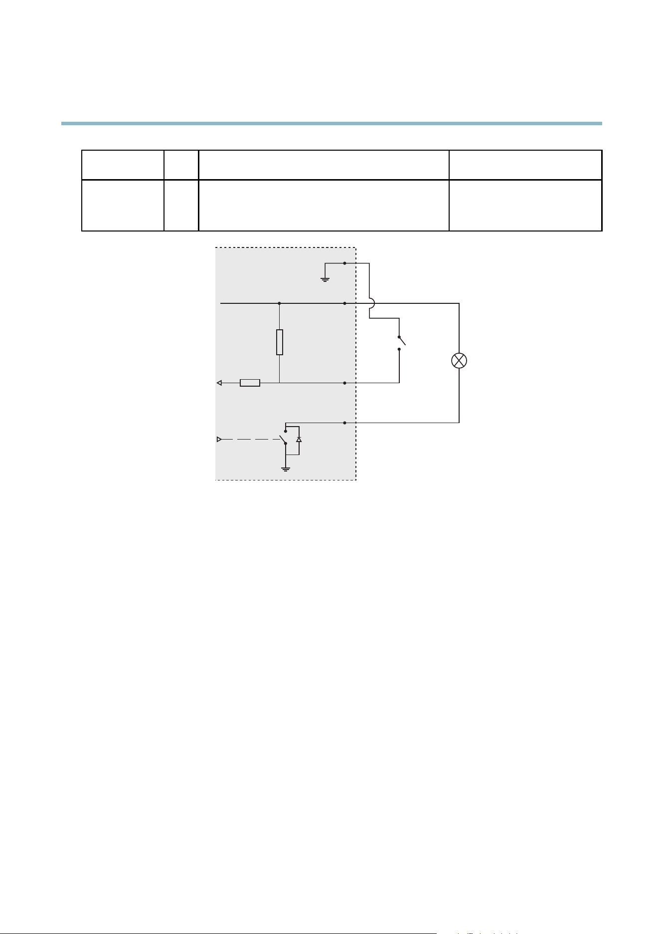
AXIS M1143–L
Technical Specifications
Digital Input
3
Connect to GND to activate, or leave floating (unconnected)
to deactivate.
0to+40VDC
Digital Output
4
Internal connection to ground when activated, floating
(unconnected) when deactivated. If used with an inductive
load, e.g. a relay, a diode must be connected in parallel with
the load, for protection against voltag e transients .
Max load =100 mA
Max voltage = + 40 V DC
3.3 V max 50 mA
1
2
3
4
Performance Considerations
When settings up your system, it is important to consider how various setting s and situations will affect perfor m ance. Some factors
affect the amount of bandwidth (the bit rate) required, others can affect the frame rate, and some aff ect both. If the load on the
CPU reaches its maxim um, this wi ll also affect the fra m e rate.
The following factors are among the most imp ortant to consider:
• High image resolution and/or lower compression levels result in images containing more data. Bandwidth affected.
• Access by large numbers of Motion JPEG and/or unicast H.264 clients. Bandwidth affected.
• Simultaneous viewing of different streams (resolution, compression) by different clients. Effect on frame rate and bandwidth.
• Accessing Motion JPEG and H.264 video stre ams s imultane ous ly. Frame rate and bandwidth affe cted.
• Heavy usage of event settings a ffect the product’s CPU load. Frame rate affected.
• Heavy network utilization due to poor infrastructure . Bandwidth affected.
• Viewing on poorly performing client computers lowers perceived performance. Frame rate affected.
52

User Manual Ver. M1.10
AXIS M1143–
L Date: June 201
2
© Axis Communications AB, 2012
Part No. 45
407