Loading ...
Loading ...
Loading ...
12
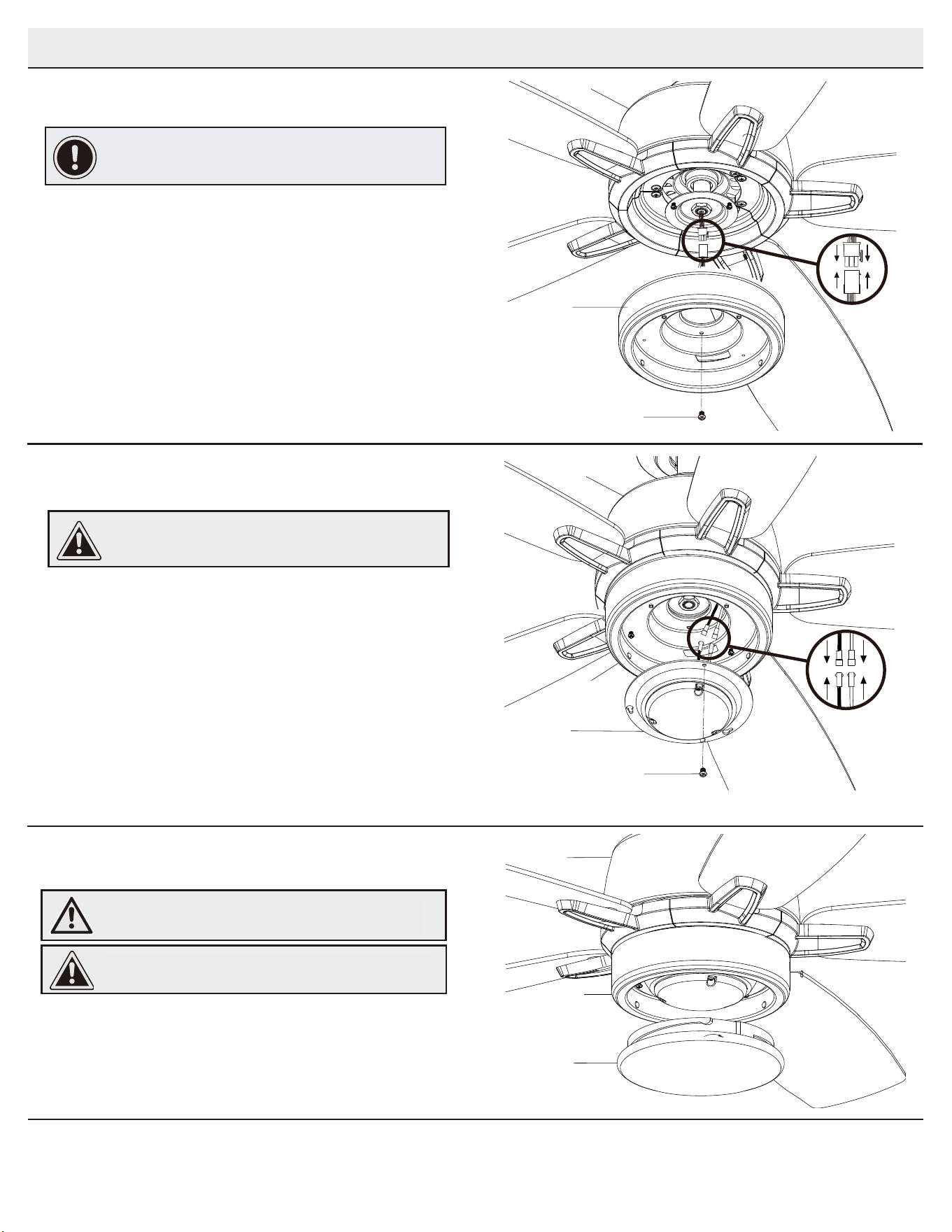
Installing the glass bowl
3
Ƒ Place the glass bowl (J) into the light kit pan (H), aligning the
three flat areas on the top flange of the glass bowl (J) with the
raised dimples in the light kit pan.
Ƒ Turn the glass bowl (J) clockwise until it stops.
CAUTION: Make sure the power is off before attaching or
removing the glass bowl.
WARNING: Allow the glass bowl to cool completely before
removing.
Assembly - Attaching the Lights
Attaching the light kit fitter assembly
2
Ƒ Remove one screw (PP) from the light kit pan (H) and loosen but do
not remove the other two screws.
Ƒ Connect the wires from the light kit fitter assembly (I) to the wires
from the light kit pan (H) by connecting the molded adaptor plugs
together. Carefully tuck all wires and splices into the switch cup.
Ƒ Push the light kit fitter assembly (I) up to the light kit pan (H) so that
the two loosened screw heads fit into the keyhole slots. Turn the light
kit fitter assembly (I) clockwise.
Ƒ Re-install the screw (PP) that was removed in step 1.
Ƒ Make sure all the screws are firmly tightened.
CAUTION: To reduce the risk of electric shock, disconnect
the electrical supply circuit to the fan before installing the
light fixture.
Installing the light kit pan
1
IMPORTANT: It is critical to attach the light kit pan using the
quick connector. The fan will not operate unless the light kit
pan is connected to the fan.
Ƒ Remove one screw (RR) from the black bracket below the fan
motor assembly (E), and loosen but do not remove the other
two screws.
Ƒ Connect the 9-pin plug exiting the bottom of the fan motor
assembly (E) to the 9-pin plug from the light kit pan (H). Be sure
the plug connections snap together completely.
Ƒ Push the light kit pan (H) up to the fan motor assembly (E) so
that the two loosened screw heads fit into the keyhole slots.
Turn the light kit pan (H) clockwise.
Ƒ Re-install the screw (RR) that was removed in step 1.
Ƒ Make sure all the screws are firmly tightened.
RR
H
E
I
E
PP
H
E
J
H
Remove one screw (PP) from the light kit pan (F) and loosen but do
not remove the other two screws.
Connect the wires from the LED assembly(G) to the wires
from the light kit pan (F) by connecting the molded adaptor plugs
together. Carefully tuck all wires and splices into the switch cup.
Push the LED assembly(G) up to the light kit pan (H) so that
the two loosened screw heads fit into the keyhole slots. Turn the
LED assembly(G) clockwise.
Re-install the screw (PP) that was removed in step 1.
Make sure all the screws are firmly tightened.
Attaching the LED assembly
Place the Light cover (H) into the Light kit pan (F), aligning the
three flat areas on the top flange of the Light cover (H) with the
raised dimples in the light kit pan.
Turn the Light cover (H) clockwise until it stops.
Installing the light cover
WARNING: Allow the light cover to cool
completely before removing.
CAUTION: Make sure the power is off before
attaching or removing the light cover.
C
F
C
F
G
C
F
H
Remove one screw (RR) from the black bracket below the fan
motor assembly (C), and loosen but do not remove the other
two screws.
Connect the 9-pin plug exiting the bottom of the fan motor
assembly (C) to the 9-pin plug from the light kit pan (F). Be sure
the plug connections snap together completely.
Push the light kit pan (F) up to the fan motor assembly (C) so
that the two loosened screw heads fit into the keyhole slots.
Turn the light kit pan (F) clockwise.
Re-install the screw (RR) that was removed in step 1.
Make sure all the screws are firmly tightened.
9
Loading ...
Loading ...
Loading ...