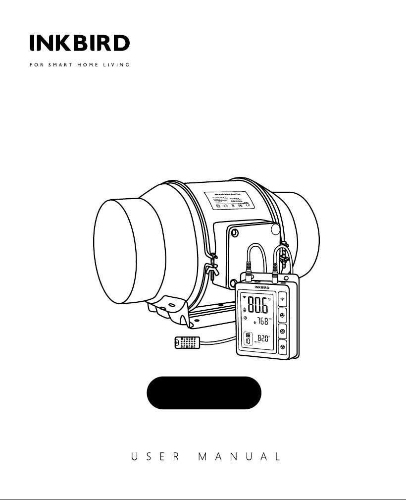
Inline Duct Fan with
Smart Controller
IVC-001W
w
A
R
R
A
N
T
Y
VOID
IF SEAL
BROKEN

01 Overview
02 Features & Specifications
03 Product Contents
04 INKBIRD App
05 Smart Controller Instructions
06 Automatic Control Mode Instructions
CONTENTS
01
01
02
03
03
04
07 Manual Control Mode Instructions
09 Shutdown Mode
10 Lock Mode
11 ECO Mode
12 Parameter Factory Setting
13 Inline Duct Fan Installation Instructions
09
13
13
13
13
14
08 Timer Control Mode Instructions
10
14 FCC Requirement
22
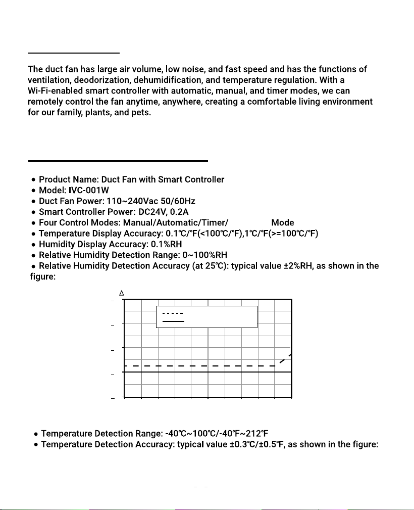
01 Overview
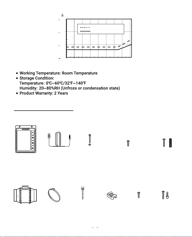
02 Features & Specifications
Shutdown
maximal tolerance
Relative Humidity(%RH)
typical tolerance
+8
RH(%RH)
+6
+4
+2
+0
0 10 20 30 40 50 60 70 80 90 100
1
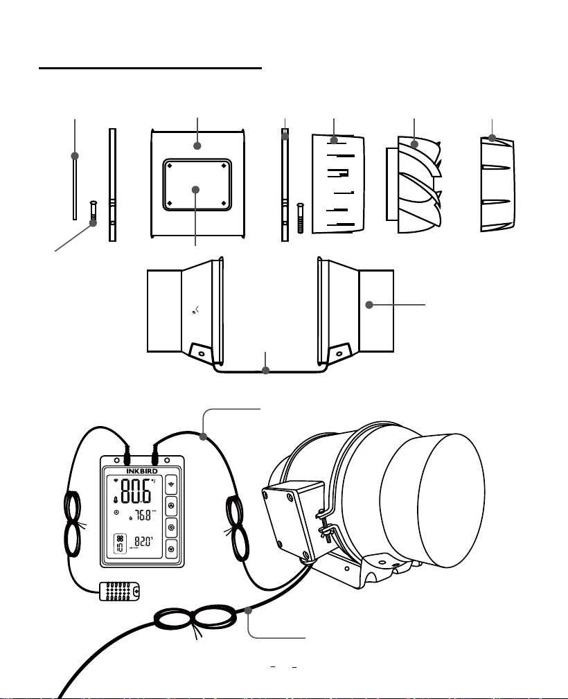
03 Product Contents
150
ALRFLOW
Temperature(℃)
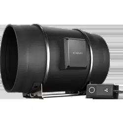
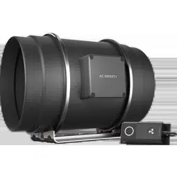
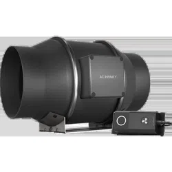
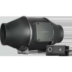
Smart Controller Unit
Inline Duct Fan Unit
SMART
CONTROLLER
(X1)
SENSOR
PROBE
(X1)
MACHINE SCREWS
(WALL MOUNT)
(X2)
WOOD SCREWS
(WALL MOUNT)
(X2)
WOOD SCREWS
(WALL HANG)
(X2)
+1.5
+1.0
+0.5
+0.0
-40 -20 0 20 40 60 80 100 120
maximal tolerance
typical tolerance
T(℃)
INLINE DUCT
FAN SYSTEM
(X1)
DUCT
CLAMP
(X2)
WIRE
TIE
(X6)
CABLE TIE
MOUNT
(X6)
WOOD
SCREWS
(X6)
2
DUCT FAN
SCREW SET
(X6)
04 INKBIRD App
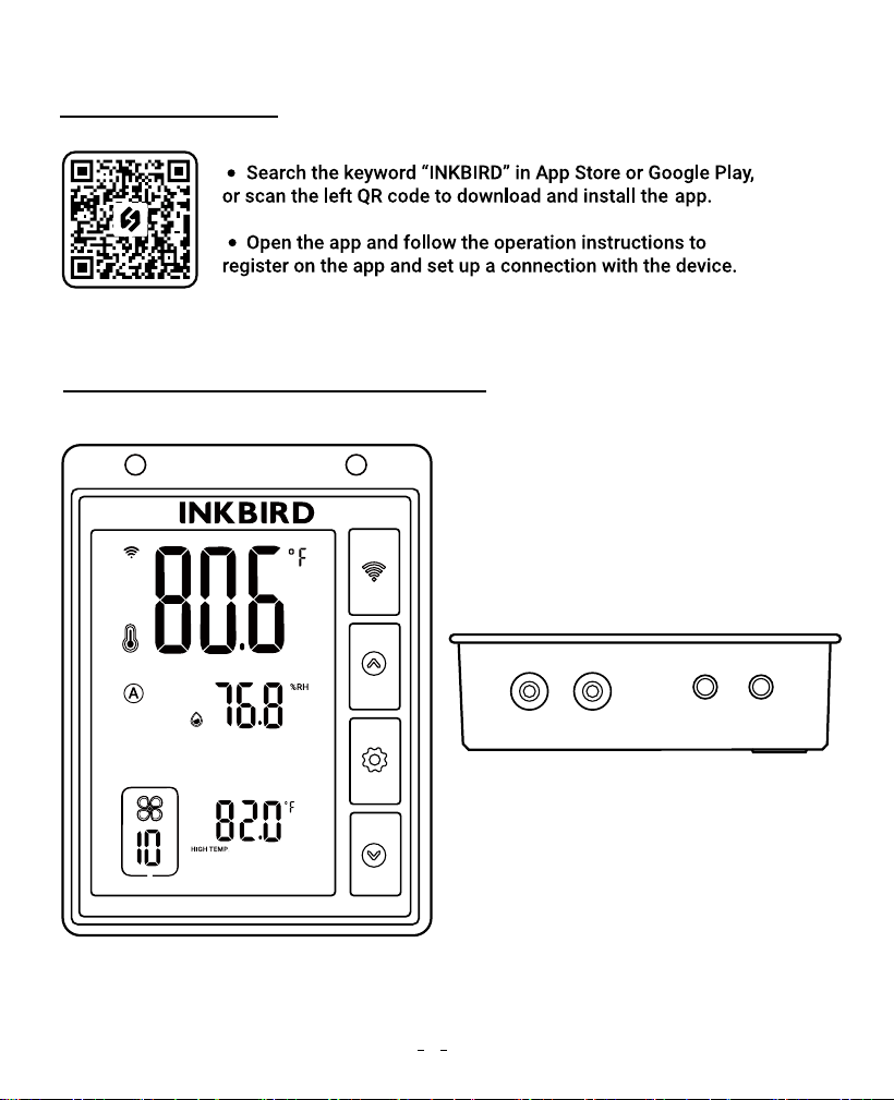
05 Smart Controller Instructions
P1 P2
WORK1 WORK2
3
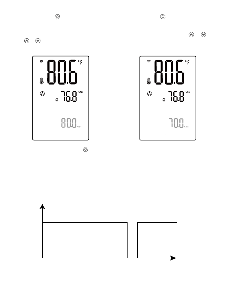
The fan will run at the set fan speed according to the relationship between the current
temperature and humidity and the trigger target temperature and humidity.
How to set the fan to run at a fan speed of 10 to keep the temperature at 81.0℉ to
82.0℉ and the humidity at 70.0%RH to 80.0% RH?
06 Automatic Control Mode Instructions
4
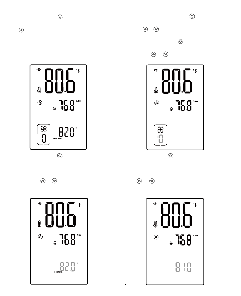
Step3: Press the button to select
the high-temperature trigger value.
“HIGH TEMP.” is displayed and the
corresponding parameter flashes.
Press the or button to adjust the
high-temperature trigger value to
82.0℉.
Step4: Press the button to select the
low-temperature trigger value. “LOW
TEMP.” is displayed and the
corresponding parameter flashes. Press
the or button to adjust the
low-temperature trigger value to 81.0℉.
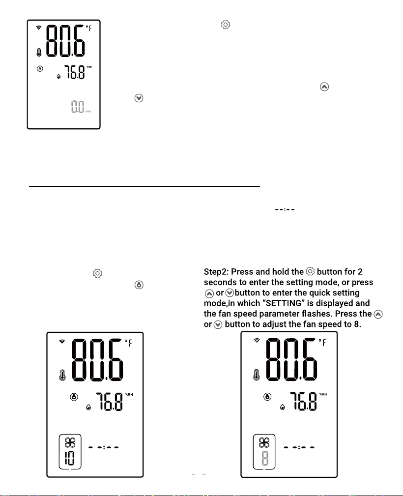
Step2: Press and hold the button for
2 seconds to enter the setting mode, or
press or button to enter the quick
setting mode, in which “SETTING” is
displayed. Press the button until the
fan speed parameter flashes, then
press the or button to adjust the
fan speed to 10.
SETTING
SETTING
SETTING
HIGH TEMP.ALARM DIFF.TEMP.VALUE
LOW TEMP.ALARM TEMP.CALIBRATION
HIGH HUMID.ALARMDIFF.HUMID.VALUE
LOW HUMID.ALARM HUMID.CALIBRATION
Step1: Press the button to select
automatic control mode, in which the
symbol is displayed.
5
Step5: Press the button to select the
high-humidity trigger value. “HIGH
HUMD.” is displayed and the
corresponding parameter flashes. Press
the or button to adjust the
high-humidity trigger value to 80.0%RH.
Step6: Press the button to select the
low-humidity trigger value. “LOW HUMD.”
is displayed and the corresponding
parameter flashes. Press the or
button to adjust the low-humidity trigger
value to 70.0%RH.
ON
OFF
SETTING
HIGH TEMP.ALARM DIFF.TEMP.VALUE
LOW TEMP.ALARM TEMP.CALIBRATION
HIGH HUMID.ALARMDIFF.HUMID.VALUE
LOW HUMID.ALARM HUMID.CALIBRATION
SETTING
HIGH TEMP.ALARM DIFF.TEMP.VALUE
LOW TEMP.ALARM TEMP.CALIBRATION
HIGH HUMID.ALARMDIFF.HUMID.VALUE
LOW HUMID.ALARM HUMID.CALIBRATION
Step7: Step7: Press and hold button for 2 seconds or no operation for 60 seconds
(or 10 seconds in the quick setting mode) to quit the setting state and save the set
parameters.
Following the above steps, the fan will run at the fan speed of 10, the temperature will
be controlled at 81.0℉~82.0℉, and the humidity will be controlled at
70.0%RH~80.0%RH, as shown below:
81.0℉ 82.0℉
Temperature trigger value
Fan status
6
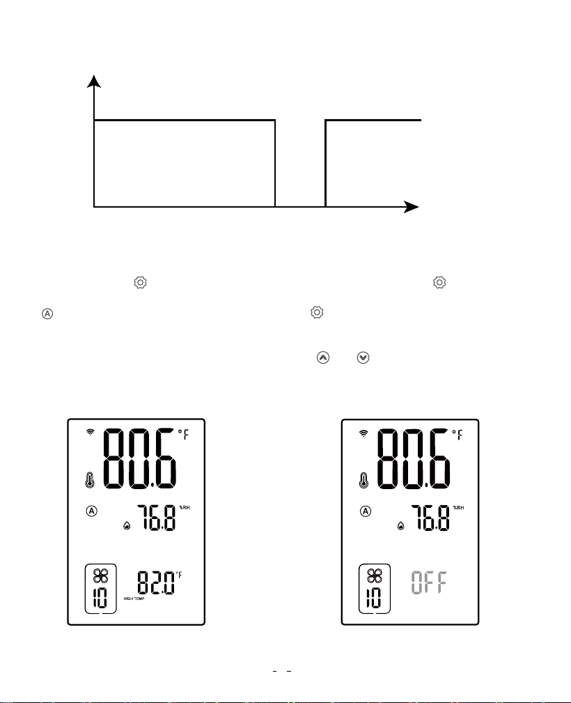
How to disable the high-temperature trigger function?
Step1: Press the button to select
automatic control mode, in which the
symbol is displayed.
Step2: Press and hold the button for 2
seconds to enter the setting mode. Press
the button to select the high-temperature
trigger value. “HIGH TEMP.” is displayed and
the corresponding parameter flashes. Press
both and buttons simultaneously and
hold for 2 seconds to display OFF and turn
off the high-temperature trigger function.
SETTING
HIGH TEMP.
ON
OFF
70.0%RH 80.0%RH
Humidity trigger value
Fan status
7
Temperature Unit High Temperature
Alarm Value
Low Temperature
Alarm Value
Temperature
Calibration Value
High Humidity
Alarm Value
Low Humidity
Alarm Value
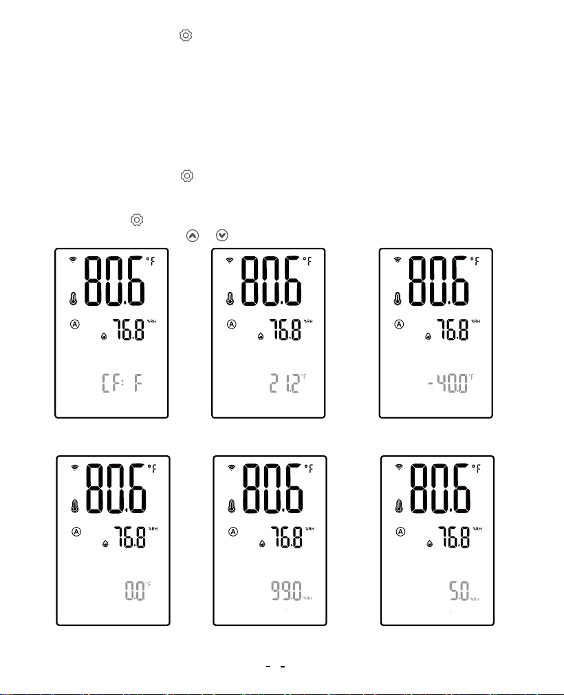
Step1: Press and hold the seconds for 2 seconds to enter the setting mode, in which
“SETTING” is displayed.
Step2: Press the button to select the parameter to set and the corresponding
characters flash. Press the or button to adjust the parameter.
Step3: Press and hold the button for 2 seconds or no operation for 60 seconds to quit
the setting state and save the set parameters.
Low-temperature trigger, high-humidity trigger, and low-humidity trigger functions can be
turned off by referring to the above steps. Note that at least one trigger function should
remain on.
How to set temperature unit/temperature alarm value/humidity alarm value/calibration
value?
SETTING
SETTING
SETTING
SETTING SETTING SETTING
HIGH TEMP.ALARM DIFF.TEMP.VALUE
LOW TEMP.ALARM TEMP.CALIBRATION
HIGH HUMID.ALARMDIFF.HUMID.VALUE
LOW HUMID.ALARM HUMID.CALIBRATION
HIGH TEMP.ALARM DIFF.TEMP.VALUE
LOW TEMP.ALARM TEMP.CALIBRATION
HIGH HUMID.ALARMDIFF.HUMID.VALUE
LOW HUMID.ALARM HUMID.CALIBRATION
HIGH TEMP.ALARM DIFF.TEMP.VALUE
LOW TEMP.ALARM TEMP.CALIBRATION
HIGH HUMID.ALARMDIFF.HUMID.VALUE
LOW HUMID.ALARM HUMID.CALIBRATION
HIGH TEMP.ALARM DIFF.TEMP.VALUE
LOW TEMP.ALARM TEMP.CALIBRATION
HIGH HUMID.ALARMDIFF.HUMID.VALUE
LOW HUMID.ALARM HUMID.CALIBRATION
HIGH TEMP.ALARM DIFF.TEMP.VALUE
LOW TEMP.ALARM TEMP.CALIBRATION
HIGH HUMID.ALARMDIFF.HUMID.VALUE
LOW HUMID.ALARM HUMID.CALIBRATION
8
Step3: Press and hold the button for 2 seconds or no
operation for 60 seconds to quit the setting state and
save the set parameters.
Note: When setting the high-temperature alarm
value/low-temperature alarm value/high-humidity alarm
value/low-humidity alarm value, press and hold the
and buttons simultaneously for 2 seconds to display
OFF and disable the corresponding alarm function.
Humidity
Calibration Value
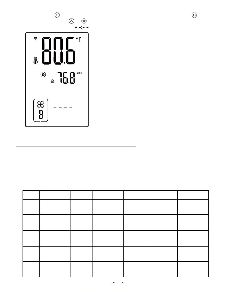
07 Manual Control Mode Instructions
Step1: Press the button to select the
manual mode, in which the symbol
is displayed.
The fan will continuously run at the set fan speed (from 0~10) and the running
time, regardless of the current temperature and humidity. When is displayed,
it means that the fan is not limited by time.
How to set the fan to run at the set fan speed without a time limit? For example,
the fan runs continuously at a fan speed of 8 until manually turned off.
SETTING
HIGH TEMP.ALARM DIFF.TEMP.VALUE
LOW TEMP.ALARM TEMP.CALIBRATION
HIGH HUMID.ALARMDIFF.HUMID.VALUE
LOW HUMID.ALARM HUMID.CALIBRATION
TIME
SETTING
9
Step3: Press the button to select the
fan run time. Press the or button
to adjust the time display .
SETTING
Step4: Step4: Press and hold button for
2 seconds or no operation for 60 seconds
(or 5 seconds in the quick setting mode) to
quit the setting state and save the set
parameters.
Following the above steps, the fun will run
continuously at a fan speed of 8 until
manually turned off.
08 Timer Control Mode Instructions
Mon. Tues.
Wed.
Thurs. Fri. Sat.
Seg.1
Seg.2
Seg.3
Seg.4
Seg.5
Start at: 7:00
Speed: 8
Duration: 2hrs
Start at: 6:00
Speed: 8
Duration: 2hrs
Start at: 8:00
Speed:7
Duration: 1hrs
Start at: 12:00
Speed: 10
Duration: 3hrs
Start at: 17:00
Speed: 9
Duration: 3hrs
Start at: 5:00
Speed: 7
Duration: 2hrs
Start at: 8:00
Speed: 10
Duration: 3hrs
Start at: 12:00
Speed: 10
Duration: 3hrs
Start at: 16:00
Speed: 10
Duration: 2hrs
Start at: 20:00
Speed: 6
Duration: 1hrs
Start at: 10:00
Speed: 10
Duration: 3hrs
Start at: 16:00
Speed: 9
Duration: 3hrs
Start at: 20:00
Speed: 7
Duration: 3hrs
Start at: 11:00
Speed: 10
Duration: 3hrs
Start at: 18:00
Speed: 9
Duration: 2hrs
The fan will run at the set fan speed according to the start time and running time of the
day you choose.
How to set the fan to run at different speeds within different run times and at multiple
start times on different days? For example, how can we set the fan to run on the
following schedule?
10
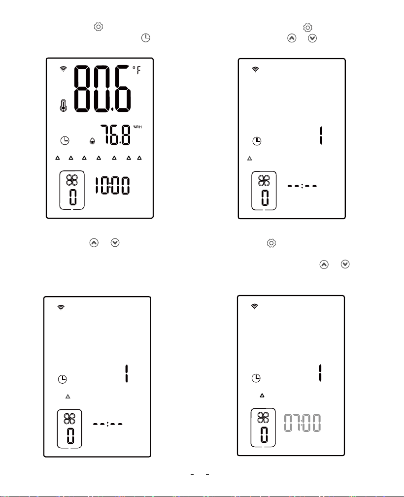
Step1: Press the button to select
the timer mode, in which the
symbol is displayed.
Step2: Press and hold the button for 2
seconds, or press the or button to enter
the setting mode.
Step3: Press the or button to
select the day to be set. Here we
choose Monday as an example.
Step4: Press the button to enter the setting
of active time segments, in which “START
TIME ” is displayed. Press the or button
to adjust the start time of segment 1 to 07:00.
SUN. MON. TUES. WED. THURS. FRI. SAT.
AM
SUN. MON. TUES. WED. THURS. FRI. SAT.
START TIME SETTING
SUN. MON. TUES. WED. THURS. FRI. SAT.
START TIME
SUN. MON. TUES. WED. THURS. FRI. SAT.
START TIME
AM
11
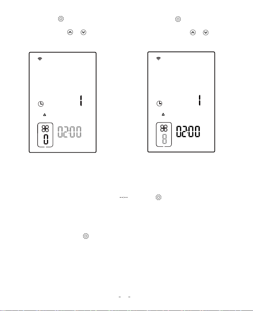
Step5: Press the button to set the run
time of segment 1, and “TIME SETTING” is
displayed. Press the or button to
adjust the run time to 02:00.
Step7: Repeat steps 4 to 6, and set the start time of segment 2 to 12:00, the run time to
03:00, and the fan speed to 10; set the start time of segment 3 to 18:00, the run time to
02:00, and the fan speed to 9.
Step8: When the start time is displayed as , press the button to return to Step 3 and
set the running state for other days.
Step9: Repeat steps 3 to 8 to set the running state parameters for Wednesday, Friday, and
Saturday.
Step10: Press and hold the button for 2 seconds or no operation for 60 seconds to quit
the setting state and save the set parameters.
The above steps can realize the daily running state of the fan in timer mode.
Step6: Press the button to set the fan
speed of segment 1, and the fan symbol
is displayed. Press the or button to
adjust the fan speed to 8.
SUN. MON. TUES. WED. THURS. FRI. SAT.
START TIME SETTING
SUN. MON. TUES. WED. THURS. FRI. SAT.
START TIME SETTING
12
09 Shutdown Mode
All control functions are disabled.
Press the button to select the shutdown mode, in which all functional controls are
turned off.
10 Lock Mode
In the non-setting state, press and hold the and button for 2 seconds simultaneously
to turn on/off the lock function. When the lock function is on, the symbol is displayed.
11 ECO Mode
In the power-off state, press and hold the button for 2 seconds to enter the setting of
backlight brightness. Press the or button to adjust the brightness percentage. After
30 seconds of no operation, the device enters ECO mode.
12 Parameter Factory Setting
After powering off, press the button, then power on the device again. All parameters in
all modes will be restored to default data.
Note that the buzzer will beep once to remind us that all parameters have been restored to
default data.
13
13 Duct Fan Instructions
DC Connect Wire
(2.4m length 26AWG)
AC Power Cord
(1.8m length 18AWG)
14
Bottom
cover
Screw
Power
cover
Butt plate
Frame Hoops
Duct-A
Duct
Duct-B
Impelle
150
ALRFLOW
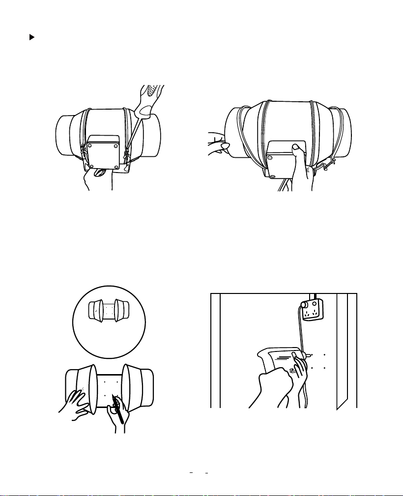
Installation Instructions
Step1: Unscrew the annular threaded nail
of the duct fan.
Step2: Remove the power supply chassis
from the rack.
Step3: Use the mounting holes of the
flange bracket to mark the position to be
mounted. (Pay attention to the direction of
intake/exhaust during installation,
referring to the instructions for intake/
exhaust.)
Step4: Drill four holes at the marked
locations. Make sure the installation area
is well constructed and free of
obstructions.
15
Intake and Exhaust
Mounting Flanges
150
ALRFLOW
150
ALRFLOW
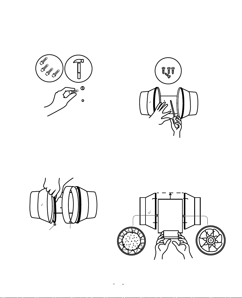
Step5: If you need plastic expansion tubes,
insert the included 4 expansion tubes into
the drilled holes and fix them in the holes
with a hammer.
Step6: Align the hole of the flange bracket
with the wall anchor, and use a screwdriver
or drill to insert the four screws to fix the
flange bracket. Make sure the airflow
arrow points in the desired direction.
Step7: Put the wind circle back on the
intake flange and reposition the flange on
the appropriate metal clips.
Step8: Move the power supply chassis
back onto the flange bracket, making sure
that the bulging part of the power supply
chassis is installed in the direction of the
flange bracket arrow. Use a Phillips
screwdriver and pliers to tighten the metal
clips and secure the power supply chassis.
Metal Clamps
Wind Circle
150
ALRFLOW
150
ALRFLO
W
150
ALRFLOW
16
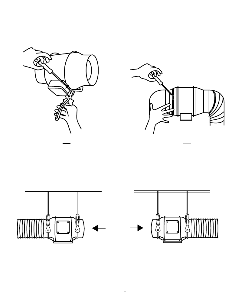
Step9: Put the metal ring back onto the
flange and tighten the screws to fix the
fan.
Step11 A: Hang Up—— If using a rope
bridge (not included) for installation,
wrap the rope around the flange and
tighten the rope to secure the fan.
Step10: When installing the duct, use the
included duct clamps to secure it to
either end of the duct fan, making sure it
is tightly sealed. Use a flat-head
screwdriver to tighten the duct clamps.
Step11 B: Hang Down You can also
wrap the rope around the fan mounting
plate to hang the fan. Tighten the rope to
secure the fan and make sure the fan
airflow arrow points in the desired
direction.
17
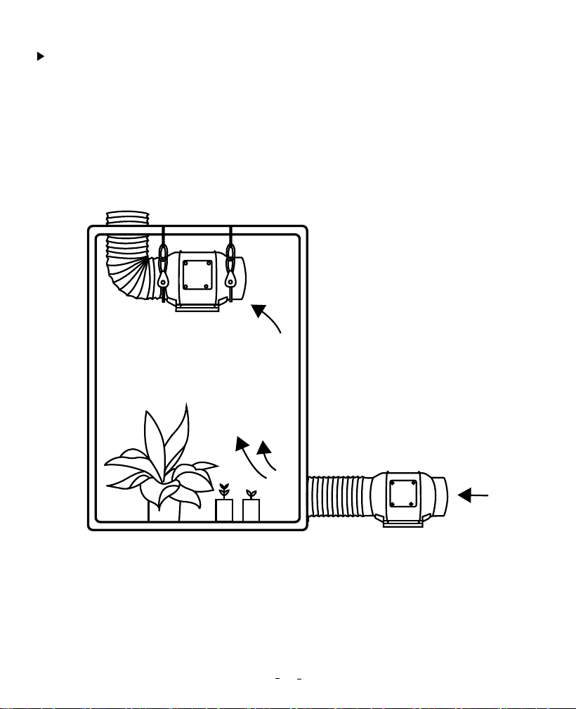
This duct fan can be used as an intake machine or exhaust machine in greenhouses and
large grow tents. For optimal ventilation of the space, intake fans or openings (without
fans) must be placed in the bottom corners of the growing space, and exhaust fans
must be hung (as shown below) or mounted in the corresponding highest corners. Make
sure the airflow arrow of the intake fan points towards the growing space and the arrow
of the exhaust fan points away from the growing space.
Intake & Exhaust
18
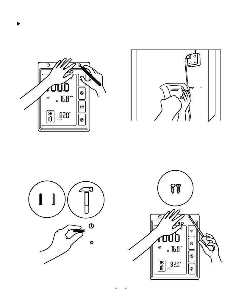
Controller Power Up and Setting
Step 1: Mark the locations to be mounted
with the mounting holes on the controller.
Pay attention to the fan power cable
length and the probe length.
Step2: Drill 2 holes at the marked locations.
Step3: If you need plastic expansion
tubes, insert the included 2 expansion
tubes into the drilled holes and fix them
in the holes with a hammer.
Step4: Align the mounting holes on the
controller with the wall anchor, and insert
the two screws with a screwdriver or drill.
19
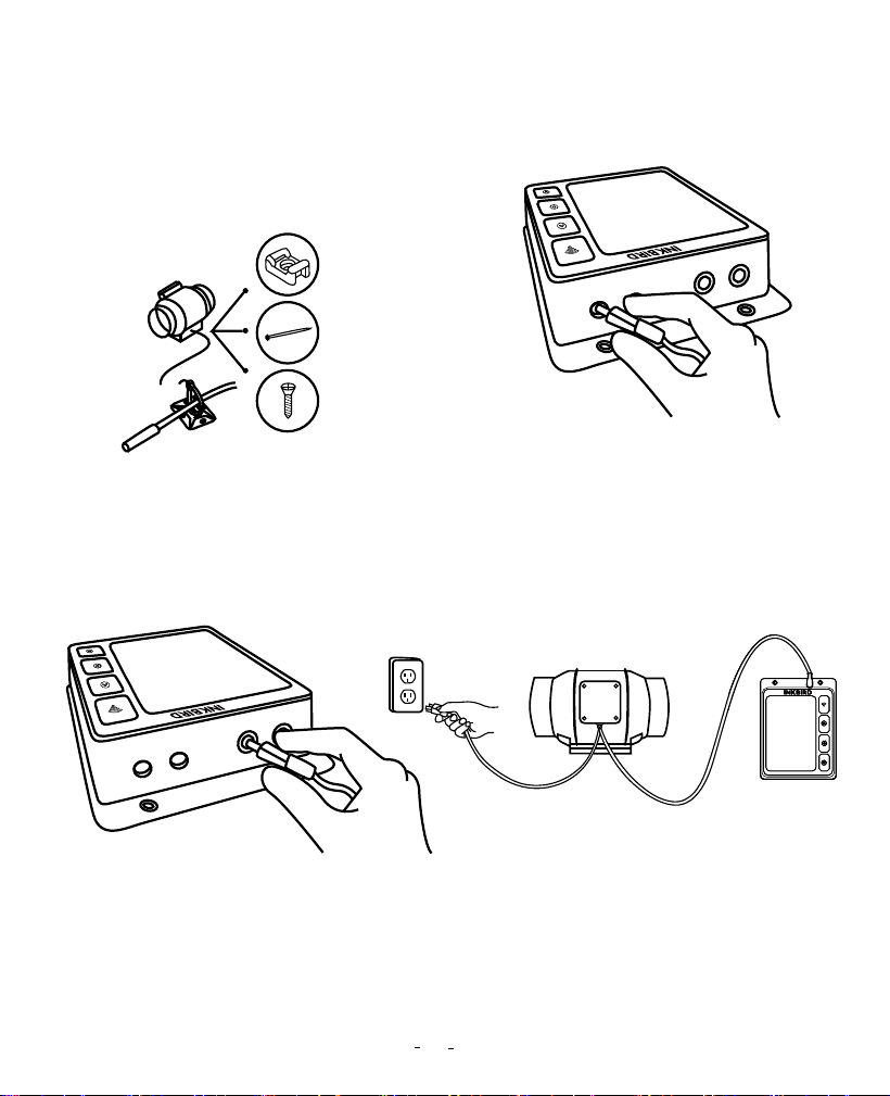
Step5: You can organize your cables
using the included tie bracket, screws,
and cable ties. Use screws to secure the
cable tie to the surface. Wrap the cable
tie around the rope and put it into the tie
bracket.
Step6: Insert the probe of the duct fan into
the WORK1/WORK2 port of the controller.
Step7: Insert the temperature and
humidity sensor probe into the P1/P2
port of the controller. Then, place the
probe near the plant in the grow tent for
the most accurate reading.
Step8: Finally, plug the fan power cable
into the power socket.
20
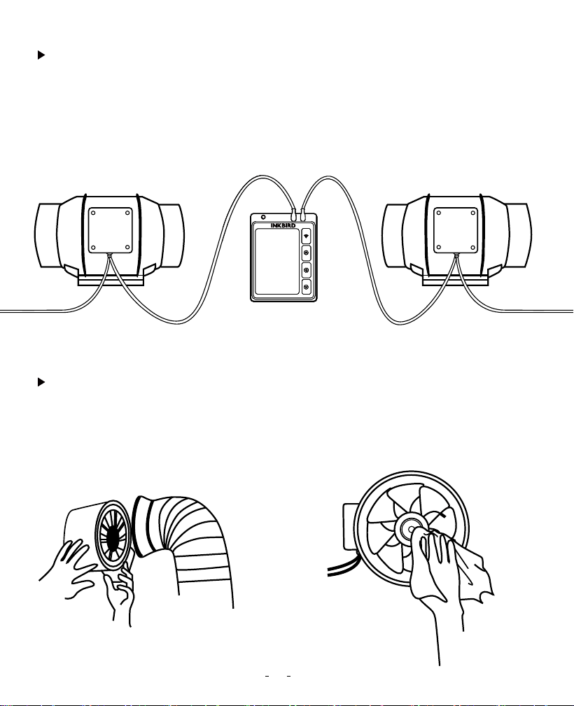
This smart controller can control two fans simultaneously. Insert the two fans into the
WORK1 and WORK 2 ports separately, as shown below:
Step1: Remove the power supply chassis
from the flange. (See steps 1 and 2 in the
installation instructions on how to
remove the power supply chassis.)
Step2: Use a wet cloth to remove dust and
debris from the wind circle and fan blades.
Add More Fans
Cleaning & Maintenance
Dual Connection
IVC-001W T6 IVC-001W T6
21

Step3: Remove dust and debris from the
other side of the stator blade and clean
the inner areas of the intake and exhaust
flanges.
Step4: See steps 7 to 9 in the installation
instructions to secure the power supply
chassis on the flange.
Changes or modifications not expressly approved by the party responsible for compliance
could void the user’s authority to operate the equipment. This device complies with Part
15 of the FCC Rules. Operation is subject to the following two conditions:
(1) this device may not cause harmful interference, and
(2) this device must accept any interference received, including interference that may
cause undesired operation.
Note: This equipment has been tested and found to comply with the limits for a Class B
digital device, pursuant to Part 15 of the FCC Rules. These limits are designed to provide
reasonable protection against harmful interference in a residential installation. This
equipment generates, uses, and can radiate radio frequency energy, and if not installed
and used in accordance with the instructions, may cause harmful interference to radio
communications. However, there is no guarantee that interference will not occur in a
particular installation. If this equipment does cause harmful interference to radio or
television reception, which can be determined by turning the equipment off and on, the
user is encouraged to try to correct the interference by one or more of the following
measures:
14 FCC Requirement
22
– Reorient or relocate the receiving antenna.
– Increase the separation between the equipment and receiver.
– Connect the equipment into an outlet on a circuit different from that to which the
receiver is connected.
– Consult the dealer or an experienced radio/TV technician for help.
This equipment complies with FCC radiation exposure limits set forth for an uncontrolled
environment. This equipment should be installed and operated with a minimum distance
of 20cm between the radiator & your body. This transmitter must not be co-located or
operating in conjunction with any other antenna or transmitter.
Attached Table 1: Parameter Description In Manual Mode
Icon Function
Fan running time
Fan Speed 0~10 10
Setting Range
or 00:01~09:00
means no time limit.
Default Setting
TIME
23
Attached Table 2: Parameter Description In Automatic Mode
Icon Function
High-temperature
trigger value
-40℃~100℃/-40℉~212℉
or OFF (disable
high-temperature trigger)
25.0℃/77.0℉
Temperature Unit
Fan Speed 0~10 10
Setting Range
℃ or ℉ ℉
Default Setting
CF:F
High Temp.
Low-temperature
trigger value
40℃~100℃/-40℉~212℉
or OFF (disable
low-temperature trigger)
20.0℃/68.0℉
Low Temp.
High-temperature
alarm value
-40℃~100℃/-40℉~212℉
or OFF (disable
high-temperature alarm)
100℃/212℉
High Temp.
Alarm
Low-temperature
alarm value
-40℃~100℃/-40℉~212℉
or OFF (disable
low-temperature alarm)
40.0℃/-40.0℉
Low Temp.
Alarm
Temperature
calibration value
-4.9℃~4.9℃/-9.9℉~9.9℉
0.0℃/0.0℉
Temp.
Calibration
Low-humidity
trigger value
0.0%RH~100%RH
or OFF (disable
low-humidity trigger)
45.0%RH
Low Humid.
High-humidity
alarm value
0.0%RH~100%RH
or OFF (disable
high-humidity alarm)
99.0%RH
High Humid.
Alarm
Low-humidity
alarm value
0.0%RH~100%RH
or OFF (disable
low-humidity alarm)
5.0%RH
Low Humid.
Alarm
Humidity
calibration value
-20.0%RH~20.0%RH
0.0%RH
Humid.
Calibration
High-humidity
trigger value
0.0%RH~100%RH
or OFF (disable
high-humidity trigger)
50.0%RH
High Humid.
24
V1.0