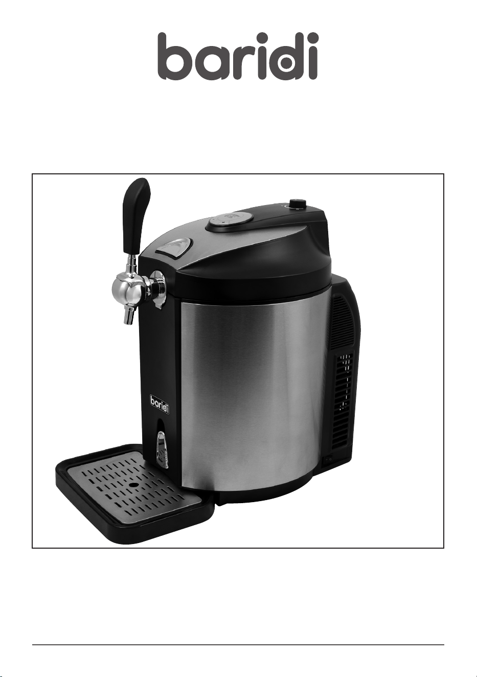
Baridi 5L Mini Keg Draft Beer Dispenser
Tap 4°C Integrated Cooling
Model No. DH49
Thank you for purchasing a Baridi product from the Dellonda range. Manufactured to a high standard,
this product will, if used according to these instructions, and properly maintained, give you years of
trouble free performance.
DH49 V1 Issue 6 05/06/2024

2
Important Information
Please read these instructions carefully and note any safe operational requirements, warnings &
cautions. Use the product correctly and with care for the purpose for which it is intended. Failure
to do so may cause damage and/or personal injury and will invalidate the warranty. Keep these
instructions safe for future use.
• ELECTRICAL SAFETY
• WARNING: It is the user’s responsibility to
check the following:
• Check all electrical equipment and appliances
to ensure that they are safe before using.
Inspect power supply leads, plugs and all
electrical connections for wear and damage.
Sealey recommend that an RCD (Residual
Current Device) is used with all electrical
products.
• Electrical safety information. It is important
that the following information is read and
understood:
• Ensure that the insulation on all cables and on
the appliance is safe before connecting it to
the power supply.
• Regularly inspect power supply cables and
plugs for wear or damage and check all
connections to ensure that they are secure.
• Important: Ensure that the voltage rating on
the appliance suits the power supply to be
used and that the plug is tted with the correct
fuse.
• DO NOT pull or carry the appliance by the
power cable.
• DO NOT pull the plug from the socket by the
cable.
• DO NOT use worn or damaged cables, plugs
or connectors. Ensure that any faulty item
is repaired or is replaced immediately by a
qualied electrician.
• If the cable or plug is damaged during use,
switch off the electricity supply and remove
from use.
• Ensure that repairs are carried out by a
qualied electrician.
• GENERAL SAFETY
• DO NOT remove keg until fully empty.
• DO NOT remove CO
2
cartridge until fully empty.
• DO NOT cover the unit while working.
• DO NOT place in direct sunlight.
• WARNING: Ensure the supply cord is not
trapped or damaged.
• Alcohol should not the consumed by any
person who is not of a legal age to do so.
• Children should be supervised at all times
around this equipment.
• INTRODUCTION
• Universal tting for most 5L beer kegs.
Thermoelectric cooling technology chills beer
to as low as 4°C. Keeps beer fresh for up to 30
days. Removable drip tray with raised lip helps
prevent spillage. LED temperature gauge.
Operates using standard 16g CO2 canisters.
Modern stainless steel and black design.
Supplied with 3 x 16g CO2 canisters and
universal attachment kit to t most 5L kegs.
• SPECIFICATION
• Model no: DH49
• Lowest temperature: 4°C
• Rated current: 0.76A
• Voltage: 220-240V
• Frequency: 50Hz
• Noise level: ≤38dB(A); Ambient noise ≤25dB(A)
• Dimensions (W x D x H): 335 x 460 x 470mm
• Keg capacity: 5L
• Supplied with 3 x 16g CO2 canisters and
universal attachment kit to t all 5L kegs.
Refer to
instructions
Indoor use
only
3
• INSTRUCTIONAL VIDEO
• An instructional video to help with the setup and use of this product is available at:-
https://www.dellonda.co.uk/pages/baridi-beer-dispenser-set-up
• LOCATION
• DO NOT locate the unit in a damp or moist location.
• Operate unit on dry and level surface.
• NOTE: The unit is designed to be free-standing and to ensure adequate ventilation, leave at least 12
cm free space around the unit.
• Once in position allow the unit to rest for an hour before turning it on.
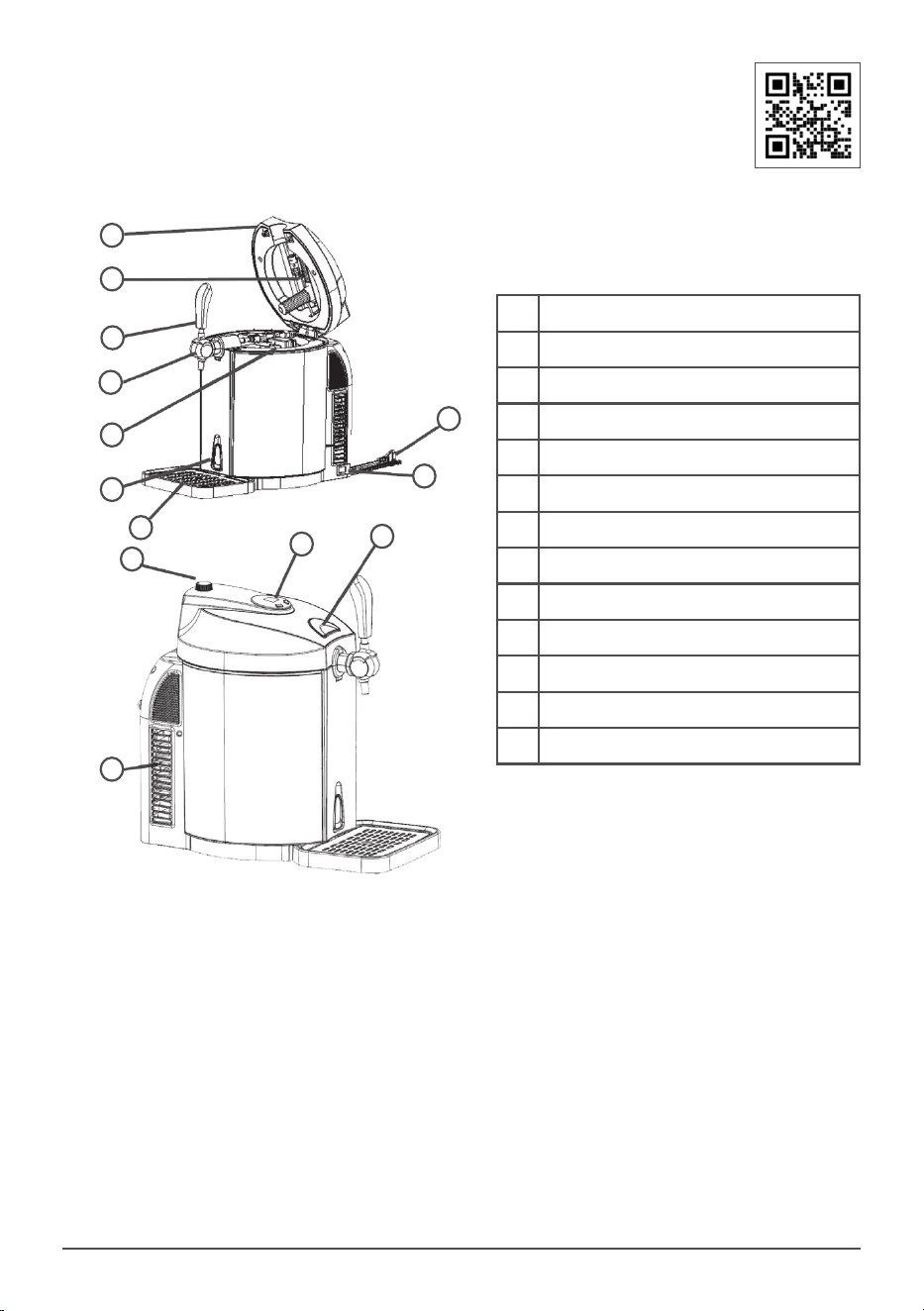
1 Keg compartment lid
2 CO2 Cannister housing
3 Beer tap handle
4 Beer tap
5 Beer dispenser/T bar
6 Water drain release
7 Drip tray
8 CO2 Pressure control knob
9 LED Display
10 Keg compartment lid release
11 Rear vent cover
12 Power cable
13 Power On/Off switch
1
2
5
3
4
7
6
8
9
10
11
12
13
4
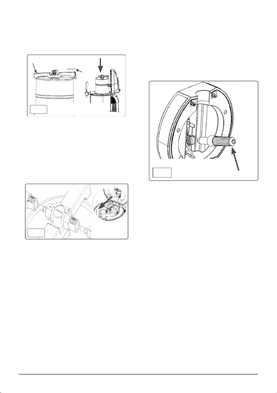
• To remove the adaptor squeeze side tabs to
release (g.2).
• USING A UNIVERSAL KEG
• NOTE: Allow beer to fully settle before
attempting to t dispensing unit.
• NOTE: DO NOT leave keg standing in direct
sunlight or near a heat source.
• NOTE: It is recommended that you allow the
keg to cool for some time before use (ideally
have it pre chilled if possible).
• NOTE: Carefully read any information
provided by the beer manufacturer that
relates to the keg and its operation.
• If tted, remove keg safety clasp according to
keg manufacturers instructions.
• Pierce keg seal with beer dispensing unit
probe (g.3).
• Push the tube down as far as it will go in
order to be able to t dispenser unit onto the
keg rim.
• If the keg seal is of the type that is fully
removable, use the supplied tapered seal
(g.10)(Accessories) to make a leak proof
seal.
• The seal ts over the open bottom end of the
• IDENTIFY YOUR KEG
• Firstly it is important to know what type of keg you
wish to load into your beer dispenser
• This will determine how to set up this dispenser.
• Universal kegs that require the use of a CO2
cannister to pressurise them will require the use of
the beer dispenser unit/T bar setup
• Kegs that are already pressurised such as Heineken
can be connected directly to the outlet tap, this
dispenser is supplied with 3 suitable keg adaptors
for this purpose.
• Both methods have a different setup.
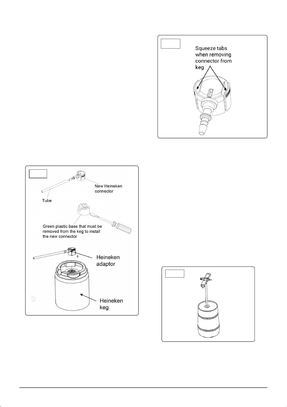
• USING A HEINEKEN KEG
• NOTE: Heineken kegs are pre-charged with CO
2
and
DO NOT need use of the gas regulator control.
• NOTE: Before connecting the keg ensure
• that the beer delivery tap is in the fully
closed position.
• Remove the plastic security cap from the
keg using a at head screwdriver. (Fig. 1)
• Place the keg into the dispenser, line up the cut out
to allow the beer delivery tube to pass through.
• Attach to the Heineken adaptor (g.1) and the clear
beer delivery tube, feed this into the tap head as
shown (Fig.8) before clipping it to the Heineken
beer keg.
• Mount the adaptor into the keg by pressing it into
keg outlet and clipping it in place.
• Carefully close the top cover.
Fig.1
Fig.2
Fig.3
5
housing with the thin neck pointing upwards.
• Check that the ‘O’ ring seal in the head of the
unit is in situ and in good condition. Replace
seal if in doubt (Fig. 13).
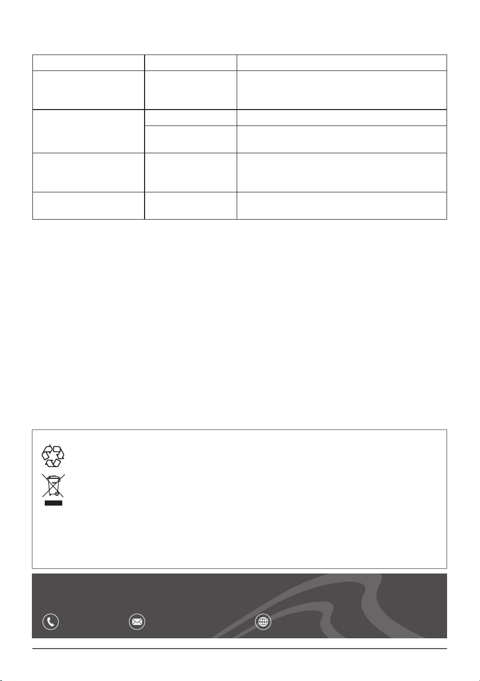
• Screw the cannister back into the unit until you
hear the seal break and the initial rush of gas
leave the cannister to pressurise the system.
• Tighten down the housing until you feel it
reach the bottom of the thread. (Fig. 6)
• DO NOT over tighten.
• DO NOT attempt to remove or change a
cartridge if it is not completely empty, this
can dislodge or damage the ‘O’ ring and seals
within the system and cause damage to the
unit and you.
• It is safe to change a CO
2
cannister mid keg as
long as the cartridge is completely empty.
• NOTE: Ensure that the pressure control
valve is set to fully closed before attempting
removal or replacement of a gas cylinder.
• NOTE: If the beer keg is empty ensure you
draw of the last of the CO
2
cannister before
reloading the dispenser, this is done simply
by opening the beer delivery tap allowing the
balance of gas to escape.
• NOTE: The cartridge mount has an ‘O’ ring
seal. If the seal is proven to be leaking, it
should be replaced. Replacement ‘O’ rings are
supplied in the kit.
• NOTE: The cartridge used on this unit is NOT
the threaded type.
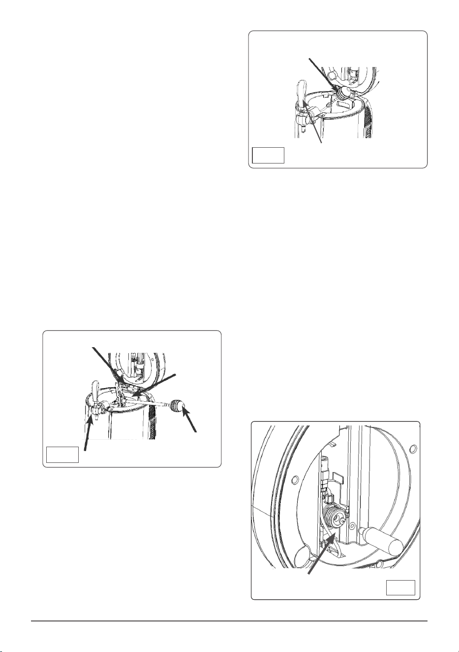
• BEER DISPENSING UNIT
• The beer dispensing unit or ‘T’ bar should
come with the unit assembled, if not or if you
choose to take it apart for cleaning please
follow these instructions.
delivery tube on the dispensing unit.
• Clip the beer dispenser T bar over the rim of
the keg on both sides (Fig. 4)
• To remove press the release tab shown on
the right.
• NOTE: The dispensing unit has a directional
arrow that indicates the direction of CO
2
ow
through it.
• Ensure that the arrows on the ow valve are
pointing towards the pouring tap.
• Connect CO
2
feed pipe and beer delivery tube
to either side of the ow valve by depressing
white tabs to allow full and leak proof
engagement (Fig. 5).
• With the keg connected check to ensure the
tubes will not get trapped and close the lid of
the dispenser.
• Using the LED display set the required
temperature as described in ‘Operation’.
• Allow the unit and beer to settle, you will then
be ready to open the gas ow valve and begin
pouring.
• SETUP FOR UNIVERSAL KEGS (CO2
CARTRIDGE).
• Ensure the gas pressure control is closed on
top of the unit with the dot all the way over to
the ‘-’ side.(Fig. 9).
• To t a CO2 cannister fold down and then
unscrew the cartridge housing in the
underside of the units lid (Fig.6).
• Place a new CO2
cannister into the cartridge
Clip over the rim
Carefully lower the keg
assembly into the dispenser.
Fig.4
Flow direction arrows
Fig.5
CO2 ows from the
cannister towards
the beer tap
CO2 Cartridge housing
Fig.6
6
• To assemble the dispensing unit pass the pick
up tube on the underside of the ow valve
through the main body (Fig. 7).
• NOTE ensure the small peg on the underside
of the ow valve is orientated to line up with
the cut out in the main body moulding (g.7)
NOTE: It can only t in one direction.
• Screw the delivery tube over the pick up tube
on the underside of the assembly making
sure that the ‘O’ ring seal is in situ and in
good condition in the top of the delivery tube.
Replace seal if in doubt.
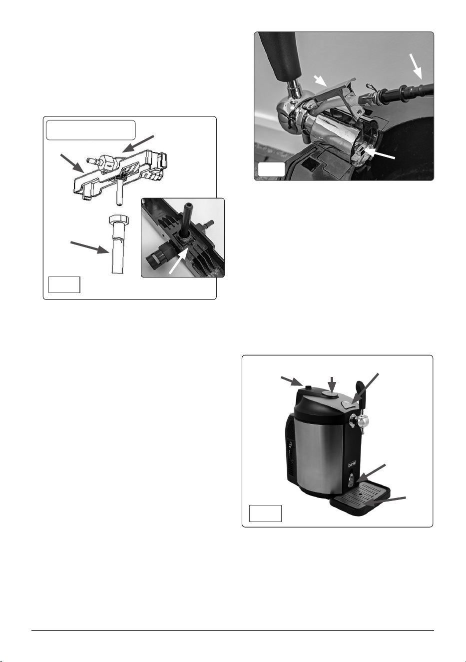
• CONNECT DISPENSER TUBE INTO
THE TAP HEAD
• Assemble clear hose and connector as g.8.
• Lift the lid of the unit and press the release
button on the inside of the tap head to release
the centre section of the tap body (g.8).
• Place the clear hose through the hole in the
removable centre section and while pushing
the tap handle down in the open position (as
if your were pouring a beer), thread the clear
hose down into the tap head to the bottom.
• NOTE: Ensure a rm leak proof location within
the tap body. Relocate centre section back to
original position and clip down.
Fig.7
Main body
Delivery tube
Beer dispensing unit
Orientation peg
• OPERATION
• Read this document thoroughly and assemble
the unit accordingly.
• Check that the unit is fully assembled and
installed in the appropriate location.
• Ensure that CO
2
valve is fully closed.
• Locate drip tray (g.9) into body and make
sure that the cooling water release is in the
closed position (upright) (Fig.9).
• Open the lid release, you will see in the bottom
of the unit a height marker on the wall ‘MAX’.
• Carefully pour 800 ml of clean cold tap water
into the chamber up to the ‘MAX’ mark.
• Cold water will help the unit get to temperature
faster.
• DO NOT ll past the ‘MAX’ mark on the inside
of the chamber.
• Now select the preferred temperature for the
cooling water you have just added to the unit,
(when you add the keg this liquid will form a
cooling jacket around the beer keg.
• Select a temperature setting using the LED
Cooling
Water
Release
LED Display
Drip Tray
Lid Release
Fig.9
Gas Pressure
Control
Connect to the ow valve
Release
button
Centre section
(Released)
Fig. 8
Flow valve
7
interface on the top of the unit (g.9).
• NOTE: The LED display shows the current
temperature of the beer and pressing and
holding the ‘+’ key displays the temperature
you have set the unit at to chill down to.
• Press and hold the ‘+’ key and then use the ‘+’
and ‘-’ keys to set the temperature.
• Allow the unit time to reach the set
temperature before placing keg into the
cooling compartment.
• If using a ‘universal’ beer keg, open the
pressure control valve (g.9) to regulate the
ow of gas and gently pull the tap handle to
begin pouring.
• Use the pressure control valve to control the
beer’s ow rate and level of frothing.
• If serving Heineken beer, ensure the pressure
control valve is fully closed as the kegs have
their own internal pressurising device hence
there is no need to use a CO2 cannister to
pressurise the keg.
• LED INTERFACE
• When the unit has been switched on, the LED
is activated.
• The interface will show the current beer
temperature.
• NOTE: To cool a beer keg to 4
o
C may take up
to 20 hours depending on initial beer temp
and ambient temp.
• The unit has a temperature setting range of
between 4
o
C and 12
o
C.
• To set a required beer temperature use the ‘+’
or ‘-’ key to set the value.
• To display the current set value press the ‘-’
button for one second. The display will return
to the current beer temperature after three
seconds.
• NOTE: The unit has a memory function that
uses the last selected temperature.
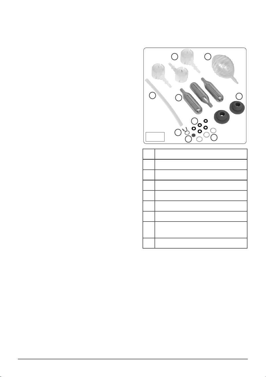
• ACCESSORIES
• The Baridi beer dispenser is supplied with a
number of additional components and some
spare parts.
• CLEANING AND MAINTENANCE
• Remove the power plug from the supply when
performing cleaning or maintenance.
• It is recommended to replace the water inside
the unit once each week.
• Before draining the water, ensure that the drip
tray is properly engaged in the unit to avoid
spillage.
• When the drip tray is properly engaged, lower
the drain ap (item 6 on the explanation
diagram) to allow water to ow out of the
unit.
1
2
5
3
4
7
6
8
9
1 Heineken keg adaptor.
2 Clear tube
3 16g CO2 Cannisters
4 Water bulb
5 Tube clip
6 CO2 piercing tool ‘O’ ring
7 CO2 piercing tool
8 Large ‘O’ ring (Flow valve/Delivery
tube)
9 Open keg style delivery tube adaptor
Fig.10
8
• NOTE: The drip tray only has a volume of
approximately 400 ml while the unit has a
volume of approximately 800 ml. Hence
attention will need to be paid to the draining
process to avoid spillage.
• Alternatively remove the drip tray, slide the
dispenser to the edge of the table and hold at
least a 1L jug under the drain pipe, open the
drain lever on the face of the unit and allow
the water to drain out.
• Close the drain lever before adding fresh
water.
• Cleaning the internals of the unit is imperative
to meet hygiene requirements. Clean before
rst use or long periods of non-use.
• Clean all internals ONLY with warm, clean
water.
• Cleaning the unit when changing kegs of
dierent beers is also recommended to
improve your drinking experience.
• Disconnect the CO2 gas feed hose from the
dispensing unit and hold the tap in the open
position. Using the water bulb lled with
clean, warm water, force water through the
tube and out through the tap. Repeat until
satised that the unit is clean.
• Withdraw the beer dispensing unit from the
keg and using the water bulb ush the unit
through (Fig. 11) shows the process for
universal kegs requiring the CO2 connection.
Repeat until satised that the unit is clean.
• For pressurised kegs unclip the keg adaptor
from the top of the keg and clean as shown
(Fig. 12). Repeat until satised that the unit
is clean.
• DO NOT use abrasive or chemical cleaning
materials on any surface of the unit.
• Wipe interior and exterior surfaces with a
damp cloth and dry thoroughly with a clean
dry cloth.
• For more soiled surfaces use a neutral
detergent, wipe down with a clean damp cloth
and dry thoroughly with a clean dry cloth.
• CARTRIDGE PIERCING TOOL
• The cartridges used in this unit are of the blind
type i.e. they are NOT threaded. As such they
require piercing in order to operate.
• Should the piercing tool need replacing,
remove the empty gas cartridge.
• Carefully remove the ‘O’ ring seal from the
cartridge nest and lift out the installed piercing
tool (g.13).
• Insert the replacement piercing tool and ‘O’
ring noting that the orientation of the piercing
point is towards an inserted gas cartridge.
Disconnect the CO2 supply tube
Fig.11
Open the tap
Flush clean
water through
the system
Disconnect the keg adaptor
Fig.12
Open the tap
Flush clean
water through
the system
Fig.13
Pierce tool and ‘O’ ring
9
• TROUBLESHOOTING
Symptom Possible cause Possible solution
Unit does not operate. Not plugged in.
Fuse/circuit breaker
failure.
Plug in and turn power on. Use qualied
electrician to investigate.
Slow beer ow Low gas pressure. Increase gas pressure. Replace cartridge.
Connection
incorrect.
Check hose connections.
Too much head on beer Gas pressure too
high. Beer temp too
high. Low beer level.
Adjust gas pressure.
Allow beer to cool further.
Check keg contents and renew if empty.
Gas cartridge empties too
quickly.
Connection seal
faulty.
Check ‘O’ ring seal. Replace if damaged.
Dellonda Limited, Sole UK Distributor of Baridi
Kempson Way, Suffolk Business Park, Bury St Edmunds, Suffolk. IP32 7AR
01284 757575 [email protected] www.dellonda.co.uk
Environment Protection, Waste Electrical and Waste
Electronic Equipment Regulations (WEEE)
Recycle unwanted packaging materials. When this product is no longer required, or has
reached the end of its useful life, please dispose of in an environmentally friendly way.
Drain any uids (if applicable) into approved containers, in accordance with local waste
regulations. It is our policy to continually improve products and we reserve the right to alter
data, specications and parts without prior notice. No liability is accepted for incorrect use
of this product. Guarantee is 12 months from purchase date, proof of which is required for
any claim.