
Digital Oscilloscope Series
1
Programming Guide
Digital Oscilloscopes
RC01-E02A
2018 SIGLENT TECHNOLOGIES CO., LTD

Digital Oscilloscope Series
2
Version Declaration
This chapter declares the modifications of command in the most recent release
of the programming guide version.
Version E02A at Introduction
This version, as the second new version, regulates all the currently available
commands. Some of the commands vary between series, and these will be
annotated in the description of command.
The following are the main revisions:
Delete the Table of Commands & Queries, and all the instructions are
classified according to the functional modules.
Removed incorrect instructions, added instructions for WGEN and DIGITAL
modules.
Add two new communication features: Telnet and Socket, visible in
―Programming Overview-Remote Control‖.
Detailed programming instances for instructions (WF?/SCDP) to make it
easier to understand.
Support obtaining waveform data of Digital channel and Math.
For comparison with the previous programming guide, differences have been
listed in ―Obsolete Commands for Old Models‖.

Digital Oscilloscope Series
3
Content
Programming Overview ..................................................................................... 6
Establishing Communications ........................................................................ 6
Install NI-VISA .......................................................................................... 6
Connect the Instrument ............................................................................. 10
Remote Control ............................................................................................ 11
User-defined Programming....................................................................... 11
Send SCPI Commands via NI-MAX ........................................................ 11
Using SCPI with Telnet ............................................................................ 11
Using SCPI with Sockets .......................................................................... 13
Introduction to the SCPI Language .................................................................. 14
About Commands & Queries ........................................................................ 14
Description ................................................................................................... 14
Usage ............................................................................................................ 14
Command Notation....................................................................................... 15
Commands & Queries ...................................................................................... 17
COMMON (*) Commands ........................................................................... 18
COMM_HEADER Commands .................................................................... 22
ACQUIRE Commands ................................................................................. 24
AUTOSET Commands ................................................................................. 38
CHANNEL Commands ................................................................................ 40
CURSOR Commands ................................................................................... 50
DIGITAL Commands ................................................................................... 58
DISPLAY Commands .................................................................................. 68
HISTORY Commands .................................................................................. 74

Digital Oscilloscope Series
4
MATH Commands ........................................................................................ 79
MEASURE Commands ................................................................................. 96
PASS/FAIL Commands .............................................................................. 110
PRINT Commands ...................................................................................... 122
RECALL Commands .................................................................................. 124
REFERENCE Commands ........................................................................... 128
SAVE Commands ....................................................................................... 138
STATUS Commands................................................................................... 145
SYSTEM Commands .................................................................................. 148
TIMEBASE Commands .............................................................................. 153
TRIGGER Commands ................................................................................ 161
WAVEFORM Commands .......................................................................... 178
WGEN Commands ...................................................................................... 192
Obsolete Commands for Old Models .......................................................... 199
Programming Examples .................................................................................. 223
VISA Examples ........................................................................................... 224
VC++ Example........................................................................................ 224
VB Example ............................................................................................ 231
MATLAB Example ................................................................................. 237
LabVIEW Example ................................................................................. 239
C# Example ............................................................................................. 242
Examples of Using Sockets ......................................................................... 245
Python Example ...................................................................................... 245
C Example ............................................................................................... 248
Common Command Examples .................................................................... 250
Read waveform data (WF) Example ....................................................... 250


Digital Oscilloscope Series
6
Programming Overview
This chapter introduces how to build communication between the instrument
and the PC. It also introduces how to configure a system for remote instrument
control.
By using USB and LAN interfaces, in combination with NI-VISA and
programming languages, users can remotely control the instruments. Through
LAN interface, VXI-11, Sockets and Telnet protocols can be used to
communicate with the instruments.
Establishing Communications
Install NI-VISA
Before programming, you need to install the National Instruments NI-VISA
library, which you can download from the National Instruments web site.
Currently, NI-VISA is packaged in two versions: a full version and a Run-Time
Engine version. The full version includes the NI device drivers and a tool
named NI MAX which is a user interface to control and test remotely connected
devices. The Run-Time Engine is recommended, as it is a much smaller
download than the full version and includes the necessary tools for basic
communication to instruments.
For example, you can get the NI-VISA 5.4 full version from:
http://www.ni.com/download/ni-visa-5.4/4230/en/.
You also can download NI-VISA Run-Time Engine 5.4 to your PC and install it
as the default selection. Its installation process is similar with the full version.
After you downloaded the file, follow these steps to install NI-VISA (The full
version of NI-VISA 5.4 is used in this example. Newer versions are likely, and
should be compatible with SIGLENT instrumentation. Download the latest
version available for the operating system being used by the controlling
computer):
a. Double click the visa540_full.exe, dialog shown as below:
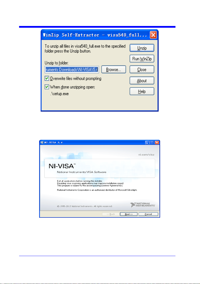
Digital Oscilloscope Series
7
b. Click Unzip, the installation process will automatically launch after
unzipping files. If your computer needs to install .NET Framework 4, it may
auto start.
c. The NI-VISA installing dialog is shown above. Click Next to start the
installation process.
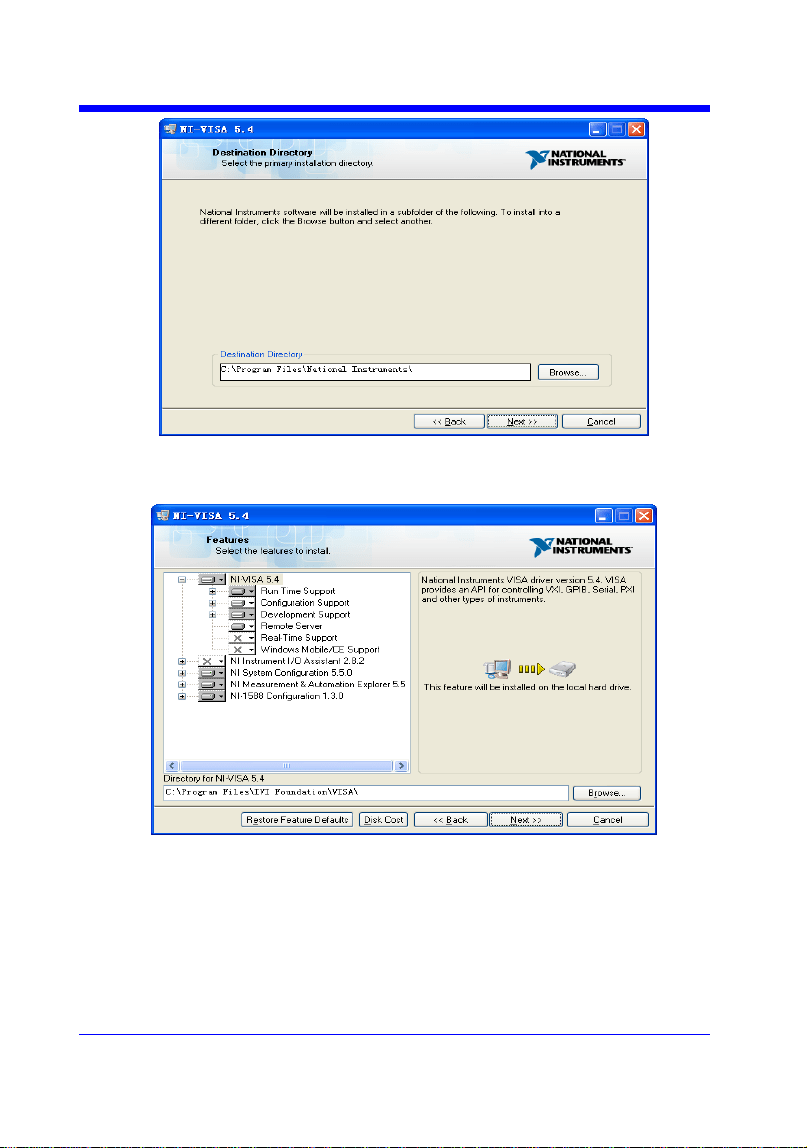
Digital Oscilloscope Series
8
d. Set the install path, default path is ―C:\Program Files\National Instruments\‖,
you can change it. Click Next, dialog shown as above.
e. Click Next twice, in the License Agreement dialog, select the ―I accept the
above 2 License Agreement(s).‖,and click Next, dialog shown as below:
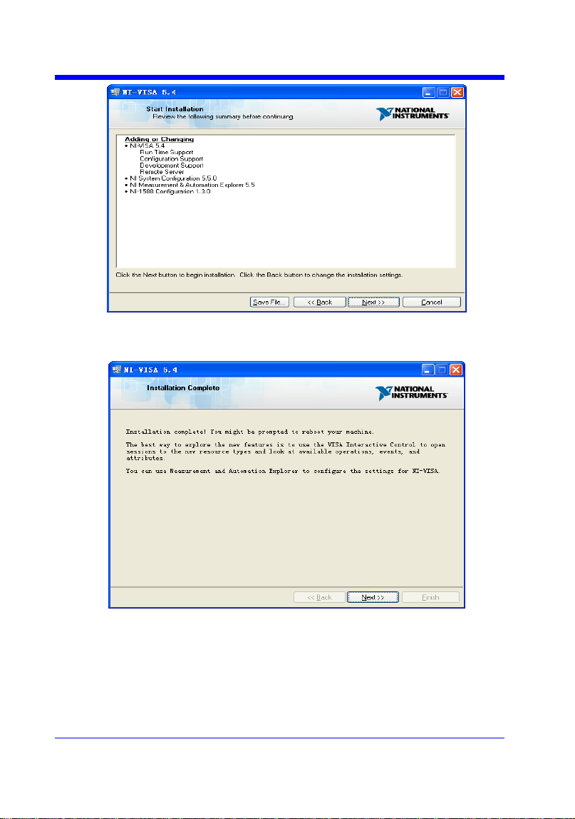
Digital Oscilloscope Series
9
f. Click Next to begin installation.
g. Now the installation is complete. Reboot your PC.
Digital Oscilloscope Series
10
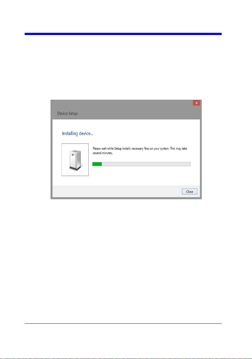
Connect the Instrument
Depending on the specific model, your oscilloscope may be able to
communicate with a PC through the USB or LAN interface.
Connect the instrument and the USB Host interface of the PC using a USB
cable. Assuming your PC is already turned on, turn on your oscilloscope, and
then the PC will display the ―Device Setup‖ screen as it automatically installs
the device driver as shown below.
Wait for the installation to complete and then proceed to the next step.

Digital Oscilloscope Series
11
Remote Control
User-defined Programming
Users can use SCPI commands via a computer to program and control the
digital oscilloscope. For details, refer to the introductions in "Programming
Examples".
Send SCPI Commands via NI-MAX
NI-Measurement and Automation eXplorer (NI-MAX) is a program created and
maintained by National Instruments. It provides a basic remote control interface
for VXI, LAN, USB, GPIB, and Serial communications. It is a utility that
enables you to send commands one-at-a-time and also retrieve data from
connected devices. It is a great tool for troubleshooting and testing command
sequences. The oscilloscopes can be controlled remotely by sending SCPI
commands via NI-MAX.
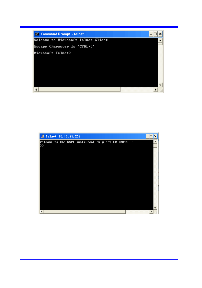
Using SCPI with Telnet
Telnet provides a means of communicating with the oscilloscopes over a LAN
connection. The Telnet protocol sends SCPI commands to the oscilloscopes
from a PC and is similar to communicating with the oscilloscopes over USB. It
sends and receives information interactively: one command at a time. Windows
operating systems use a command prompt style interface for the Telnet client.
The steps are as follows:
1. On your PC, click Start > All Programs > Accessories > Command Prompt.
2. At the command prompt, type in telnet.
3. Press the Enter key. The Telnet display screen will be displayed.
Digital Oscilloscope Series
12
4. At the Telnet command line, type:
open XXX.XXX.XXX.XXX 5024
Where XXX.XXX.XXX.XXX is the instrument‘s IP address and 5024 is the port.
You should see a response similar to the following:
5. At the SCPI> prompt, input the SCPI commands such as *IDN? to return
the company name, model number, serial number, and firmware version
number.

Digital Oscilloscope Series
13
6. To exit the SCPI> session, press the Ctrl+] keys simultaneously.
7. Type quit at the prompt or close the Telnet window to close the connection
to the instrument and exit Telnet.
Using SCPI with Sockets
Socket API can be used to control the SDS1000X-E series via LAN without
installing any other libraries. This can reduce the complexity of programming.
SOCKET ADDRESS IP address + port number
IP ADDRESS SDS IP address
PORT NUMBER 5024
Please see section "Examples of Using Sockets" for the details.

Digital Oscilloscope Series
14
Introduction to the SCPI Language
About Commands & Queries
This section lists and describes the remote control commands and queries
recognized by the instrument. All commands and queries can be executed in
either local or remote state.
The description for each command or query, with syntax and other information,
begins on a new page. The name (header) is given in both long and short form
at the top of the page, and the subject is indicated as a command or query or
both.
The commands are given in long format for the ―COMMAND SYNTAX‖ and
―QUERY SYNTAX‖ sections and they are used in a short form for the
―EXAMPLE‖.
Queries perform actions such as obtaining information, and are recognized by
the question mark (?) following the header.
Description
In the description, a brief explanation of the function performed is given. This is
followed by a presentation of the formal syntax, with the header given in upper
case characters and the short form derived from it. Where applicable, the syntax
of the query is given with the format of its response.
Usage
The commands and queries listed here can be used for SIGLENTs Digital
Oscilloscope Series as shown below. Models are arranged according to their
initial release dates.
Applicable to the following models
SDS1000CFL
non-SPO model
SDS1000A
non-SPO model

Digital Oscilloscope Series
15
SDS1000CML+/CNL+/DL+/E+/F+
non-SPO model
SDS2000/2000X
SPO model
SDS1000X/1000X+
SPO model
SDS1000X-E/X-C
SPO model
What is an SPO model?
Oscilloscope models that have the SPO designation use SIGLENTs
innovative waveform acquisition and graphics processing engine which
supports high capture rate, multi-level intensity grading and color
temperature display. SPO models also come with deep memory storage and
the use of new digital trigger technology that supports rich precise trigger
types.
Command Notation
The following notations are used in the commands:
< > Angular brackets enclose words that are used as placeholders, of which
there are two types: the header path and the data parameter of a command.
:= A colon followed by an equals sign separates a placeholder from the
description of the type and range of values that may be used in a
command instead of the placeholder.
{ } Braces enclose a list of choices, one of which one must be made.
[ ] Square brackets enclose optional items.
… An ellipsis indicates that the items both to its left and right may be
repeated for a number of times.
As an example, consider the syntax notation for the command to set the vertical
input sensitivity:
<channel>:VOLT_DIV <v_gain>
<channel>:={C1,C2,C3,C4}
<v_gain>:= 2 mV to 10 V
The first line shows the formal appearance of the command, with <channel>
denoting the placeholder for the header path and <v_gain> the placeholder for
the data parameter specifying the desired vertical gain value. The second line
indicates that one of four channels must be chosen for the header path. And the

Digital Oscilloscope Series
16
third explains that the actual vertical gain can be set to any value between 2 mV
and 10 V.

Digital Oscilloscope Series
17
Commands & Queries
This chapter introduces each command subsystem of the SIGLENTs Digital
Oscilloscope Series command set. The contents of this chapter are shown as
below:
COMMON (*) Commands
COMM_HEADER Commands
ACQUIRE Commands
AUTOSET Commands
CHANNEL Commands
CURSOR Commands
DIGITAL Commands
DISPLAY Commands
HISTORY Commands
MATH Commands
MEASURE Commands
PASS/FAIL Commands
PRINT Commands
RECALL Commands
REFERENCE Commands
SAVE Commands
STATUS Commands
SYSTEM Commands
TIMEBASE Commands
TRIGGER Commands
WAVEFORM Commands
WGEN Commands
Obsolete Commands for Old Models

Digital Oscilloscope Series
18
COMMON (*) Commands
The IEEE 488.2 standard defines some general commands for querying the
basic information of an instrument or performing common basic operations.
These commands usually start with *, and the command key length is 3
characters.
*IDN? (Identification Number)
*OPC (Operation Complete)
*RST (Reset)

Digital Oscilloscope Series
19
COMMON (*)
*IDN?
Query
DESCRIPTION
The *IDN? query identifies the instrument type
and software version. The response consists of
four different fields providing information on the
manufacturer, the scope model, the serial
number and the firmware revision.
QUERY SYNTAX
*IDN?
RESPONSE FORMAT
Siglent Technologies,<model>,<serial
number>,<firmware>
<model>:= the model number of the instrument.
<serial number>:= A 14-digit decimal code.
<firmware>:= the software revision of the
instrument
EXAMPLE
The query identifies the instrument type and
software version.
Command message:
*IDN?
Response message:
Siglent Technologies,SDS1204X-
E,SDS1EBAC0L0098,7.6.1.15

Digital Oscilloscope Series
20
COMMON (*)
*OPC
Command/Query
DESCRIPTION
The *OPC command sets the operation complete
bit in the Standard Event Status Register when
all pending device operations have finished.
The *OPC? query places an ASCII "1" in the
output queue when all pending device operations
have completed. The interface hangs until this
query returns.
COMMAND SYNTAX
*OPC
QUERY SYNTAX
*OPC?
RESPONSE FORMAT
*OPC 1

Digital Oscilloscope Series
21
COMMON (*)
*RST
Command
DESCRIPTION
The *RST command initiates a device reset.
This is the same as pressing [Default] on
the front panel.
COMMAND SYNTAX
*RST
EXAMPLE
This example resets the oscilloscope.
Command message:
*RST


Digital Oscilloscope Series
23
COMM_HEADER
COMM_HEADER | CHDR
Command/ Query
DESCRIPTION
The COMM_HEADER command controls the
way the oscilloscope formats response to
queries. This command does not affect the
interpretation of messages sent to the
oscilloscope. Headers can be sent in their long or
short form regardless of the CHDR setting.
Examples of the three response formats to
―C1:VDIV?‖:
CHDR
RESPONSE
LONG
C1:VOLT_DIV 1.00E+01V
SHORT
C1:VDIV 1.00E+01V
OFF
1.00E+01
COMMAND SYNTAX
COMM_HEADER <mode>
<mode>:={SHORT,LONG,OFF}
• SHORT — response starts with the short form
of the header word.
• LONG — response starts with the long form
of the header word.
• OFF — header is omitted from the response
and units in numbers are suppressed.
Note:
Default is the SHORT response format.
QUERY SYNTAX
COMM_HEADER?
RESPONSE FORMAT
COMM_HEADER <mode>
EXAMPLE
The following command sets the response
header format to SHORT.
Command message:
CHDR SHORT


Digital Oscilloscope Series
25
ACQUIRE
ARM_ACQUISITION | ARM
Command
DESCRIPTION
The ARM_ACQUISITION command starts a
new signal acquisition.
COMMAND SYNTAX
ARM_ACQUISITION
EXAMPLE
The following steps show the effect of ARM.
Note:
INR bit 13 (8192) = Trigger is ready.
INR bit 0 (1) = New Signal Acquired.
Step 1: Set the trigger mode to single, and input
a signal which can be triggered. Once triggered,
you can see the state of acquisition changes to
stop. Send the query.
Query message:
INR?
Response message:
INR 8193(trigger ready)
Step 2: Send the query again to clear the
register.
Query message:
INR?
Response message:
INR 0
Step 3; Now, send the command to start a new
signal acquisition.
Command message:
ARM
Step 4: Send the query to see the effect of ARM.
Query message:
INR?


Digital Oscilloscope Series
28
ACQUIRE
ACQUIRE_WAY | ACQW
Command /Query
DESCRIPTION
The ACQUIRE_WAY command specifies the
acquisition mode.
The ACQUIRE_WAY? query returns the current
acquisition mode.
COMMAND SYNTAX
ACQUIRE_WAY <mode>[,<time>]
<mode>:={SAMPLING,PEAK_DETECT,AVE
RAGE,HIGH_RES}
<time>:={4,16,32,64,128,256,512,…}
• SAMPLING — sets the oscilloscope in the
normal mode.
• PEAK_DETECT — sets the oscilloscope in
the peak detect mode.
• AVERAGE — sets the oscilloscope in the
averaging mode.
• HIGH_RES — sets the oscilloscope in the
enhanced resolution mode (also known as
smoothing). This is essentially a digital boxcar
filter and is used to reduce noise at slower
sweep speeds.
Note:
• The [HIGH_RES] option is valid for SPO
models. See models on page 14.
• <time>:={4,16,32,64,128,256,512,…} when
<mode> = AVERAGE.
Options vary from models. See the data sheet or
the acquire menu of the oscilloscope.
QUERY SYNTAX
ACQUIRE_WAY?
RESPONSE FORMAT
ACQUIRE_WAY <mode>[,<time>]
EXAMPLE
The following command sets the acquisition
mode to average mode and also sets the average
time to 16.
Command message:


Digital Oscilloscope Series
30
ACQUIRE
AVERAGE_ACQUIRE | AVGA
Command /Query
DESCRIPTION
The AVERAGE_ACQUIRE command selects
the average times of average acquisition.
The AVERAGE_ACQUIRE? query returns the
currently selected count value for average mode.
COMMAND SYNTAX
AVERAGE_ACQUIRE <time>
<time>:= {4,16,32,64,128,256,…}
Note:
Options of <time> vary from models. See the
data sheet or the acquire menu of the
oscilloscope for details.
QUERY SYNTAX
AVERAGE_ACQUIRE?
RESPONSE FORMAT
AVERAGE_ACQUIRE <time>
EXAMPLE
The following command turns the average times
of average acquisition to 16.
Command message:
AVGA 16
RELATED COMMANDS
ACQW

Digital Oscilloscope Series
31
ACQUIRE
MEMORY_SIZE | MSIZ
Command /Query
DESCRIPTION
The MEMORY_SIZE command sets the
maximum depth of memory.
The MEMORY_SIZE? query returns the
maximum depth of memory.
COMMAND SYNTAX
MEMORY_SIZE <size>
<size>:={7K,70K,700K,7M} for non-interleaved
mode. Non-interleaved means a single channel is
active per A/D converter. Most oscilloscopes
feature two channels per A/D converter. .
<size>:={14K,140K,1.4M,14M} for interleave
mode. Interleave mode means multiple active
channels per A/D converter.
Note:
Options of <size> vary from models. See the
data sheet or the acquire menu of the
oscilloscope for details.
QUERY SYNTAX
MEMORY_SIZE?
RESPONSE FORMAT
MEMORY_SIZE <size>
EXAMPLE
The following command sets the maximum
depth of memory to 14M in interleave mode.
Command message:
MSIZ 14M

Digital Oscilloscope Series
32
ACQUIRE
SAMPLE_STATUS? | SAST?
Query
DESCRIPTION
The SAST? query returns the acquisition
status of the scope.
QUERY SYNTAX
SAST?
RESPONSE FORMAT
SAST <status>
EXAMPLE
The following query returns the acquisition
status of the scope.
Query message:
SAST?
Response message:
SAST Trig'd

Digital Oscilloscope Series
33
ACQUIRE
SAMPLE_RATE? | SARA?
Query
DESCRIPTION
The SARA? query returns the sample rate
of the scope.
QUERY SYNTAX
SARA?
DI:SARA?
• DI — digital.
RESPONSE FORMAT
SARA <value>
DI:SARA <value>
Model
Format of <value>
SDS1000X-
E
Numerical value
in E-notation with
SI unit, such as
5.00E+08Sa/s.
others
Numerical value
with measurement
unit and physical
unit, such as
1.00GSa/s.
EXAMPLE
• The following query returns the sample
rate of the analog channel.
Query message:
SARA?
Response message:
SARA 5.00E+05Sa/s
• The following query returns the sample
rate of the digital channel.
Query message:
DI:SARA?
Response message:
DI:SARA 5.00E+05Sa/s
Note:
The table shows the availability of ―DI:SARA?‖ in each digital oscilloscope series.

Digital Oscilloscope Series
34
Model
Valid?
SDS2000X
no
SDS1000X
no
SDS1000X-E
yes

Digital Oscilloscope Series
35
ACQUIRE
SAMPLE_NUM? | SANU?
Query
DESCRIPTION
The SANU? query returns the number of
data points that the hardware will acquire
from the input signal. The number of points
acquired is based on the horizontal scale
and memory/acquisition depth selections
and cannot be directly set.
QUERY SYNTAX
SANU? <channel>
<channel>:={C1,C2,C3,C4}
RESPONSE FORMAT
SANU <value>
Model
Format of <value>
SDS1000X-
E
Numerical value
in E-notation with
SI unit, such as
7.00E+05pts.
SDS2000/20
00X/1000X/
1000X+
Numerical value
with measurement
unit and physical
unit, such as 28Mpts.
others
Numerical value,
such as 1600.
EXAMPLE
The following query returns the number of
sampled points available from last
acquisition from Channel 2.
Query message:
SANU? C2
Response message:
SANU 7.00E+05pts

Digital Oscilloscope Series
36
ACQUIRE
SINXX_SAMPLE | SXSA
Command/Query
DESCRIPTION
The SINXX_SAMPLE command sets the
way of interpolation.
The SINXX_SAMPLE? query returns the
way of interpolation.
COMMAND SYNTAX
SINXX_SAMPLE <state>
<state>:={ON,OFF}
• ON — sine interpolation.
• OFF — linear interpolation.
QUERY SYNTAX
SINXX_SAMPLE?
RESPONSE FORMAT
SINXX_SAMPLE <state>
EXAMPLE
The following command sets the way of the
interpolation to sine interpolation.
Command message:
SXSA ON

Digital Oscilloscope Series
37
ACQUIRE
XY_DISPLAY | XYDS
Command /Query
DESCRIPTION
The XY_DISPLAY command enables or
disables the display of XY mode. XY mode
plots the voltage data of both channels with
respect to one-another. For example,
channel 1 vs. channel 2. This can be used to
create Lissajous curves. The standard
display mode plots voltage data vs. time.
The XY_DISPLAY? query returns whether
the XY format display is enabled.
COMMAND SYNTAX
XY_DISPLAY <state>
<state>:={ON,OFF}
QUERY SYNTAX
XY_DISPLAY?
RESPONSE FORMAT
XY_DISPLAY <state>
EXAMPLE
The following command enables the XY
format.
Command message:
XYDS ON

Digital Oscilloscope Series
38
AUTOSET Commands
The AUTOSET subsystem commands control the function of automatic
waveform setting. The oscilloscope will automatically adjust the vertical
position, the horizontal time base and the trigger mode according to the input
signal to make the waveform display to the best state.
ASET

Digital Oscilloscope Series
39
AUTOSET
AUTO_SETUP | ASET
Command
DESCRIPTION
The AUTO_SETUP command attempts to
identify the waveform type and automatically
adjusts controls to produce a usable display of
the input signal.
COMMAND SYNTAX
AUTO_SETUP
EXAMPLE
The following command instructs the
oscilloscope to perform an auto-setup.
Command message:
ASET

Digital Oscilloscope Series
40
CHANNEL Commands
The CHANNEL subsystem commands control the analog channels. Channels
are independently programmable for offset, probe, coupling, bandwidth limit,
inversion, and more functions. The channel index (1, 2, 3, or 4) specified in the
command selects the analog channel that is affected by the command.
ATTN
BWL
CPL
OFST
SKEW
TRA
UNIT
VDIV
INVS

Digital Oscilloscope Series
41
CHANNEL
ATTENUATION | ATTN
Command /Query
DESCRIPTION
The ATTENUATION command specifies the
probe attenuation factor for the selected channel.
The probe attenuation factor may be 0.1 to
10000.This command does not change the actual
input sensitivity of the oscilloscope. It changes
the reference constants for scaling the display
factors, for making automatic measurements,
and for setting trigger levels.
The ATTENUATION? query returns the current
probe attenuation factor for the selected channel.
COMMAND SYNTAX
<channel>:ATTENUATION <attenuation>
<channel>:={C1,C2,C3,C4}
<attenuation>:={0.1,0.2,0.5,1,2,5,10,20,50,100,2
00,500,1000,2000,5000,10000}
QUERY SYNTAX
<channel>:ATTENUATION?
RESPONSE FORMAT
<channel>:ATTENUATION <attenuation>
EXAMPLE
The following command sets the attenuation
factor of Channel 1 to 100:1. To ensure the data
matches the true signal voltage values, the
physical probe attenuation must match the scope
attenuation values for that input channel.
Command message:
C1:ATTN 100
RELATED COMMANDS
VDIV
OFST

Digital Oscilloscope Series
42
CHANNEL
BANDWIDTH_LIMIT | BWL
Command /Query
DESCRIPTION
BANDWIDTH_LIMIT enables or disables the
bandwidth-limiting low-pass filter. If the
bandwidth filters are on, it will limit the
bandwidth to reduce display noise. When you
turn Bandwidth Limit ON, the Bandwidth Limit
value is set to 20 MHz. It also filters the signal to
reduce noise and other unwanted high frequency
components.
The BANDWIDTH_LIMIT? query returns
whether the bandwidth filters are on.
COMMAND SYNTAX
BANDWIDTH_LIMIT<channel>,<mode>
[,<channel>,<mode>[,<channel>,<mode>[,
<channel>,<mode>]]]
<channel>:={C1,C2,C3,C4}
<mode>:={ON,OFF}
QUERY SYNTAX
BANDWIDTH_LIMIT?
RESPONSE FORMAT
BANDWIDTH_LIMIT <channel>,<mode>
[,<channel>,<mode>[,<channel>,<mode>[,
<channel>,<mode>]]]
EXAMPLE
• The following command turns on the
bandwidth filter for all channels.
Command message:
BWL C1,ON,C2,ON,C3,ON,C4,ON
• The following command turns the bandwidth
filter on for Channel 1 only.
Command message:
BWL C1,ON

Digital Oscilloscope Series
43
CHANNEL
COUPLING | CPL
Command /Query
DESCRIPTION
The COUPLING command selects the coupling
mode of the specified input channel.
The COUPLING? query returns the coupling
mode of the specified channel.
COMMAND SYNTAX
<channel>:COUPLING <coupling>
<channel>:={C1,C2,C3,C4}
<coupling>:={A1M,A50,D1M,D50,GND}
• A — alternating current.
• D — direct current.
• 1M — 1MΩ input impedance.
• 50 — 50Ω input impedance.
Note:
Options of <coupling> vary from models. See
the data sheet or the channel menu of
oscilloscope for details.
QUERY SYNTAX
<channel>:COUPLING?
RESPONSE FORMAT
<channel>:COUPLING <coupling>
EXAMPLE
The following command sets the coupling of
Channel 2 to 50 Ω, DC.
Command message:
C2:CPL D50

Digital Oscilloscope Series
44
CHANNEL
OFFSET | OFST
Command/Query
DESCRIPTION
The OFFSET command allows adjustment of the
vertical offset of the specified input channel. The
maximum ranges depend on the fixed sensitivity
setting.
The OFFSET? query returns the offset value of
the specified channel.
COMMAND SYNTAX
<channel>:OFFSET <offset>
<channel>:={C1,C2,C3,C4}
<offset>:= vertical offset value with unit, see the
data sheet for details.
Note:
• If there is no unit (V/mV/uV) added, it
defaults to volts (V).
• If you set the offset to a value outside of the
legal range, the offset value is automatically set
to the nearest legal value. Legal values are
affected by the probe attenuation setting.
QUERY SYNTAX
<channel>:OFFSET?
RESPONSE FORMAT
<channel>:OFFSET <offset>
<offset>:= Numerical value in E-notation with
SI unit.
EXAMPLE
• The following command sets the offset of
Channel 2 to -3 V.
Command message:
C2:OFST -3V
• The following command sets the offset of
Channel 1 to -50 mV.
Command message:
C1:OFST -50mV
RELATED COMMANDS
VDIV
ATTN

Digital Oscilloscope Series
45
CHANNEL
SKEW
Command/Query
DESCRIPTION
The SKEW command sets the channel-to-
channel skew factor for the specified
channel. Each analog channel can be
adjusted + or -100 ns for a total of 200 ns
difference between channels. You can use
the oscilloscope's skew control to remove
cable-delay errors between channels.
The SKEW? query returns the skew value
of the specified trace.
COMMAND SYNTAX
<trace>:SKEW <skew>
<trace>:={C1,C2,C3,C4}
<skew>:= -100 ns to +100 ns.
QUERY SYNTAX
<trace>:SKEW?
RESPONSE FORMAT
<trace>:SKEW <skew>
Model
Format of <skew>
SDS1000X-
E
Numerical value
in E-notation with
SI unit, such as
9.99E-08S.
others
Numerical value
with measurement
unit and physical
unit, such as 0.00ns.
EXAMPLE
The following command sets skew value of
Channel 1 to 3ns.
Command message:
C1:SKEW 3NS

Digital Oscilloscope Series
46
CHANNEL
TRACE | TRA
Command/Query
DESCRIPTION
The TRACE command turns the display of the
specified channel on or off.
The TRACE? query returns the current display
setting for the specified channel.
COMMAND SYNTAX
<trace>:TRACE <mode>
<trace>:={C1,C2,C3,C4}
<mode>:={ON,OFF}
QUERY SYNTAX
<trace>:TRACE?
RESPONSE FORMAT
<trace>:TRACE <mode>
EXAMPLE
The following command displays Channel 1.
Command message:
C1:TRA ON

Digital Oscilloscope Series
47
CHANNEL
UNIT
Command /Query
DESCRIPTION
The UNIT command sets the unit of the
specified trace. Measurement results, channel
sensitivity, and trigger level will reflect the
measurement units you select.
The UNIT? query returns the unit of the
specified trace.
COMMAND SYNTAX
<channel>:UNIT <type>
<channel>:={C1,C2,C3,C4}
<type>:={V,A}
QUERY SYNTAX
<channel>:UNIT?
RESPONSE FORMAT
<channel>:UNIT <type>
EXAMPLE
The following command sets the unit of
Channel 1 to V.
Command message:
C1:UNIT V

Digital Oscilloscope Series
48
CHANNEL
VOLT_DIV | VDIV
Command /Query
DESCRIPTION
The VOLT_DIV command sets the vertical
sensitivity in Volts/div.
If the probe attenuation is changed, the scale
value is multiplied by the probe's attenuation
factor.
The VOLT_DIV? query returns the vertical
sensitivity of the specified channel.
COMMAND SYNTAX
<channel>:VOLT_DIV <v_gain>
<channel>:={C1,C2,C3,C4}
<v_gain>:= 500uV to 10V.
Note:
If there is no unit (V/mV/uV) added, it
defaults to volts (V).
QUERY SYNTAX
<channel>:VOLT_DIV?
RESPONSE FORMAT
<channel>:VOLT_DIV <v_gain>
<v_gain>:= Numerical value in E-notation
with SI unit.
EXAMPLE
The following command sets the vertical
sensitivity of Channel 1 to 50 mV/div.
Command message:
C1:VDIV 50mV
RELATED COMMANDS
ATTN

Digital Oscilloscope Series
49
CHANNEL
INVERTSET | INVS
Command/Query
DESCRIPTION
The INVERTSET command mathematically
inverts the specified traces or the math
waveform.
The INVERTSET? query returns the current
state of the channel inversion.
COMMAND SYNTAX
<trace>:INVERTSET <state>
<trace>:={C1,C2,C3,C4,MATH}
<state>:= {ON,OFF}
QUERY SYNTAX
<trace>:INVERTSET?
RESPONSE FORMAT
<trace>:INVERTSET <state>
EXAMPLE
The following command inverts the trace of
Channel 1.
Command message:
C1:INVS ON

Digital Oscilloscope Series
50
CURSOR Commands
The CURSOR subsystem commands set and query the settings of X-axis
markers(X1 and X2 cursors) and the Y-axis markers (Y1 and Y2 cursors). You
can set and query the marker mode and source, the position of X and Y cursors,
and query delta X and delta Y cursor values.
CRMS
CRST
CRTY
CRVA?

Digital Oscilloscope Series
51
CURSOR
CURSOR_MEASURE | CRMS
Command /Query
DESCRIPTION
The CURSOR_MEASURE command specifies
the type of cursor or parameter measurement to
be displayed
The CURSOR_MEASURE? query returns
which cursors or parameter measurements are
currently displayed.
COMMAND SYNTAX
CURSOR_MEASURE <mode>
Format 1:
<mode>:={OFF,ON}
• OFF — manual mode.
• ON — track mode.
Format 2:
<mode>:={OFF,MANUAL,TRACK}
• OFF — close the cursors.
• MANUAL — manual mode.
• TRACK — track mode.
Note:
The table on next page shows the available
command format in each oscilloscope series.
QUERY SYNTAX
CURSOR_MEASURE?
RESPONSE FORMAT
CURSOR_MEASURE <mode>
EXAMPLE
• The following command sets cursor function
off on SDS1000X-E.
Command message:
CRMS OFF
• The following command sets cursor mode to
track mode on SDS1000X.
Command message:
CRMS ON
RELATED COMMANDS
CRVA?
CRST

Digital Oscilloscope Series
52
Format in Each Oscilloscope Series
Model
Command Format
SDS1000CFL
Format 1
SDS1000A
Format 1
SDS1000CML+/CNL+/DL+/E+/F+
Format 1
SDS2000X
Format 1
SDS1000X
Format 1
SDS1000X-E
Format 2

Digital Oscilloscope Series
53
CURSOR
CURSOR_SET | CRST
Command /Query
DESCRIPTION
The CURSOR_SET command allows the user to
position any one of the four independent cursors
at a given screen location. The positions of the
cursors can be modified or queried even if the
required cursor is not currently displayed on the
screen. When setting a cursor position, a trace
must be specified, relative to which the cursor
will be positioned.
The CURSOR_SET? query returns the current
position of the cursor(s). The values returned
depend on the grid type selected.
COMMAND SYNTAX
<trace>:CURSOR_SET
<cursor>,<position>[,<cursor>,<position>[,<cur
sor> ,<position>[,<cursor>,<position>]]]
<trace>:={C1,C2,C3,C4}
<cursor>:={VREF,VDIF,TREF,TDIF,HRDF,H
DIF}
• VREF — The voltage-value of Y1 (curA)
under manual mode.
• VDIF — The voltage-value of Y2 (curB)
under manual mode.
• TREF — The time value of X1 (curA) under
manual mode.
• TDIF — The time value of X2 (curB) under
manual mode.
• HREF — The time value of X1 (curA) under
track mode.
• HDIF — The time value of X2 (curB) under
track mode.
<position>:= -( grid/2) *DIV to (grid/2)*DIV
when <cursor> = {TREF, TDIF, HRDF, HDIF}
(horizontal)
grid: The grid numbers in horizontal direction.
<position>:= -4*DIV to 4*DIV when <cursor> =
{ VREF,VDIF}.(vertical)

Digital Oscilloscope Series
54
Note:
• The horizontal position range is related to the
size of screen.
• You need to add the unit to the position value.
QUERY SYNTAX
<trace>:CURSOR_SET?
<cursor>[,<cursor>[,<cursor>[,<cursor>]]]
<cursor>:={VREF,VDIF,TREF,TDIF,HREF,H
DIF}
RESPONSE FORMAT
<trace>:CURSOR_SET <cursor>,<position>[,
<cursor>,<position>[,<cursor>,<position>[,<cur
sor>,<position>]]]
EXAMPLE
• When the current time base is 1 us, vdiv is
500 mV, the cursor mode is manual, the
following command sets the X1 positions to -3
DIV, Y2 position to −1 DIV, using Channel 1 as
a reference.
Command message:
C1:CRST TREF,-3us,VDIF,-500mV
• When the current time base is 1 us, the cursor
mode is track, the following command sets the
X1 positions to -1 DIV, X2 position to 2 DIV,
using Channel 1 as a reference.
Command message:
C1:CRST HREF,-1us,HDIF,2us
RELATED COMMANDS
CRMS
CRVA?

Digital Oscilloscope Series
55
CURSOR
CURSOR_TYPE | CRTY
Command /Query
DESCRIPTION
The CURSOR_TYPE command specifies the
type of cursor to be displayed when the cursor
mode is manual.
The CURSOR_TYPE query returns the current
type of cursor.
COMMAND SYNTAX
CURSOR_TYPE <type>
<mode>:={X,Y,X-Y}
QUERY SYNTAX
CURSOR_TYPE?
RESPONSE FORMAT
CURSOR_TYPE <type>
EXAMPLE
The following command sets cursor type to Y.
Command message:
CRTY Y
RELATED COMMANDS
CRMS

Digital Oscilloscope Series
56
CURSOR
CURSOR_VALUE? | CRVA?
Query
DESCRIPTION
The CURSOR_VALUE? query returns the
values measured by the specified cursors for a
given trace.
QUERY SYNTAX
<trace>:CURSOR_VALUE? <mode>
<trace>:= {C1, C2, C3, C4}
<mode>:= {HREL,VREL}
• HREL — return the delta time value,
reciprocal of delta time value, X1 (curA) time
value and X2 (curB) time value.
• VREL — return the delta volt value, Y1
(curA) volt value and Y2 (curB) volt value under
manual mode.
Note:
For non-SPO models, VREL is the delta volt
value under manual mode. See models on page
14.
RESPONSE FORMAT
<trace>:CURSOR_VALUE
HREL,<delta>,<1/delta>,<value1>,<value2>
<trace>:CURSOR_VALUE
VREL,<delta>,<value1>,<value2>
EXAMPLE
When the cursor mode is manual, and the cursor
type is Y, the following query returns the
vertical value on channel 1.
Query message:


Digital Oscilloscope Series
58
DIGITAL Commands
The DIGITAL subsystem commands control the viewing of digital channels.
They also control threshold settings for groups of digital channels.
DGCH
DGST
DGTH
SW
TRA
TSM
CUS
Note:
These commands are only valid for models which have installed the MSO
option.
Availability of Digital Commands in Each Oscilloscope Series
Model
Valid?
SDS1000CFL
no
SDS1000A
no
SDS1000CML+/CNL+/DL+/E+/F+
no
SDS2000X
yes
SDS1000X
yes
SDS1000X-E
yes

Digital Oscilloscope Series
59
DIGITAL
DIGITAL_CHANNEL | DGCH
Command /Query
DESCRIPTION
The DIGITAL_CHANNEL command turns
digital display on or off for the specified
channel.
The DIGITAL_CHANNEL? query returns the
current digital display setting for the specified
channel.
COMMAND SYNTAX
<digital>:DIGITAL_STATE <state>
<digital>:={D0,D1,D2,D3,D4,D5,D6,D7,D8,D9,
D10,D11,D12,D13,D14,D15}
<state>:={OFF,ON}
QUERY SYNTAX
<digital>:DIGITAL_STATE?
RESPONSE FORMAT
<digital>:DIGITAL_STATE <state>
EXAMPLE
For SDS1000X+ series, the following command
sets D8 display on.
Command message:
D8:DGCH ON
Note:
The table below shows the availability of command in each oscilloscope series.
Model
Valid?
SDS2000X
yes
SDS1000X
yes
SDS1000X-E
no

Digital Oscilloscope Series
60
DIGITAL
DIGITAL_STATE | DGST
Command /Query
DESCRIPTION
The DIGITAL_STATE command is used to set
the state of digital.
The DIGITAL_STATE? query returns the state
of digital.
COMMAND SYNTAX
DIGITAL_STATE <state>
<state>:={OFF,ON}
QUERY SYNTAX
DIGITAL_STATE?
RESPONSE FORMAT
DIGITAL_STATE <state>
EXAMPLE
For SDS1000X+ series, the following command
sets Digital function on.
Command message:
DGST ON
Note:
The table below shows the availability of command in each oscilloscope series.
Model
Valid?
SDS2000X
yes
SDS1000X
yes
SDS1000X-E
no

Digital Oscilloscope Series
61
DIGITAL
DIGITAL_THR | DGTH
Command /Query
DESCRIPTION
The DIGITAL_THR command sets the
threshold for the specified group of channels.
The threshold is used for triggering purposes and
for displaying the digital data as high (above the
threshold) or low (below the threshold).
The DIGITAL_THR? query returns the
threshold value for the specified group of
channels.
COMMAND SYNTAX
<group>:DIGITAL_THR <type>[,<level>]
<group>:={C1,C2}
• C1 — D0-D7.
• C2 — D8-D15.
<type>:={TTL,CMOS,CMOS3.3,CMOS2.5,CU
STOM}
<level>:= -5V to 5V when <type> is CUSTOM.
Note:
• If there is no unit(V) added to <level>, it
defaults to be V.
• If you set the threshold to a value outside of
the legal range, the threshold is automatically
set to the nearest legal value.
QUERY SYNTAX
<group>:DIGITAL_THR?
RESPONSE FORMAT
Format 1:
DIGITAL_THR <type>
Format 2:
DIGITAL_THR <group>:<level>
<type>
Response Format
TTL/CMOS/CM
OS3.3/CMOS2.5
Format 1
CUSTOM
Format 2

Digital Oscilloscope Series
62
EXAMPLE
• For SDS1000X+ series, when the Digital
function is on, the following command sets the
threshold of D0-D7 to LVLCMOS3.3.
Command message:
C1:DGTH CMOS3.3
• For SDS1000X+ series, when the Digital
function is on, the following command sets the
threshold of D8-D15 to 3 V.
Command message:
C2:DGTH CUSTOM,3V
Note:
The table below shows the availability of command in each oscilloscope series.
Model
Valid?
SDS2000X
yes
SDS1000X
yes
SDS1000X-E
no

Digital Oscilloscope Series
63
DIGITAL
SWITCH | SW
Command /Query
DESCRIPTION
The SWITCH command is used to set the state
of digital.
The SWITCH? query returns the state of digital.
COMMAND SYNTAX
<function>:SWITCH <state>
<function>:={DI}
<state>:={OFF,ON}
QUERY SYNTAX
<function>:SWITCH?
RESPONSE FORMAT
<function>:SWITCH <state>
EXAMPLE
For SDS1000X-E series, the following command
sets Digital function on.
Command message:
DI:SWITCH ON
Note:
The table below shows the availability of command in each oscilloscope series.
Model
Valid?
SDS2000X
no
SDS1000X
no
SDS1000X-E
yes

Digital Oscilloscope Series
64
DIGITAL
TRACE | TRA
Command /Query
DESCRIPTION
The TRACE command turns digital display on
or off for the specified channel.
The TRACE? query returns the current digital
display setting for the specified channel.
COMMAND SYNTAX
<digital>:TRACE <state>
<digital>:={D0,D1,D2,D3,D4,D5,D6,D7,D8,D9,
D10,D11,D12,D13,D14,D15}
<state>:={OFF,ON}
QUERY SYNTAX
<digital>:TRACE?
RESPONSE FORMAT
<digital>:TRACE <state>
EXAMPLE
For SDS1000X-E series, the following command
sets D8 display on.
Command message:
D8:TRACE ON
Note:
The table below shows the availability of command in each oscilloscope series.
Model
Valid?
SDS2000X
no
SDS1000X
no
SDS1000X-E
yes

Digital Oscilloscope Series
65
DIGITAL
THRESHOLD_MODE | TSM
Command /Query
DESCRIPTION
The THRESHOLD_MODE command sets the
threshold type for the specified group of
channels. The threshold is used for triggering
purposes and for displaying the digital data as
high (above the threshold) or low (below the
threshold).
The THRESHOLD_MODE? query returns the
threshold type for the specified group of
channels.
COMMAND SYNTAX
<group>:THRESHOLD_MODE <type>
<group>:={H8,L8}
• H8 — D8-D15.
• L8 — D0-D7.
<type>:={TTL,CMOS,LVCMOS33,LVCMOS2
5,CUSTOM}
QUERY SYNTAX
<group>:THRESHOLD_MODE?
RESPONSE FORMAT
<group>:THRESHOLD_MODE <type>
EXAMPLE
For SDS1000X-E series, when the Digital
function is on, the following command sets the
threshold of D0-D7 to LVLCMOS3.3.
Command message:
L8:TSM LVCMOS33
Note:
The table below shows the availability of command in each oscilloscope series.
Model
Valid?
SDS2000X
no
SDS1000X
no
SDS1000X-E
yes

Digital Oscilloscope Series
66
DIGITAL
CUSTOM | CUS
Command /Query
DESCRIPTION
The CUSTOM command sets the threshold
value by customer for the specified group of
channels. The threshold is used for triggering
purposes and for displaying the digital data as
high (above the threshold) or low (below the
threshold).
The CUSTOM? query returns the threshold
value set by customer for the specified group of
channels.
COMMAND SYNTAX
<group>:CUSTOM <value>
<group>:={H8,L8}
• H8 — D8-D15.
• L8 — D0-D7.
<value>:= volt value with unit.
Note:
• You need to add the volt unit(V/mV) to the
value. If there is no unit added, it defaults to
volts (V).
• The range of value varies from models. See
the data sheet for details.
• An out-of-range value will be adjusted to the
closest legal value.
QUERY SYNTAX
<group>:CUSTOM?
RESPONSE FORMAT
<group>:CUSTOM <value>
EXAMPLE
For SDS1000X-E series, when the Digital
function is on, the following command sets the
threshold value of D8-D15 to 5V.
Command message:
L8:CUSTOM 5V
Note:
The table below shows the availability of command in each oscilloscope series.
Model
Valid?

Digital Oscilloscope Series
67
SDS2000X
no
SDS1000X
no
SDS1000X-E
yes


Digital Oscilloscope Series
69
DISPLAY
DOT_JOIN | DTJN
Command /Query
DESCRIPTION
The DOT_JOIN command sets the interpolation
lines between data points.
COMMAND SYNTAX
DOT_JOIN <state>
<state>:={ON,OFF}
• ON — dots. This mode displays data more
quickly than vector mode but does not draw lines
between sample points.
• OFF — vectors. This is the default mode and
draws lines between points.
QUERY SYNTAX
DOT_JOIN?
RESPONSE FORMAT
DOT_JOIN <state>
EXAMPLE
The following command turns off the
interpolation lines.
Command message:
DTJN ON

Digital Oscilloscope Series
70
DISPLAY
GRID_DISPLAY | GRDS
Command /Query
DESCRIPTION
The GRID_DISPLAY command selects the type
of the grid which is used to display.
The GRID_DISPLAY? query returns the current
type of grid.
COMMAND SYNTAX
GRID_DISPLAY <type>
< type >:={FULL,HALF,OFF}
QUERY SYNTAX
GRID_DISPLAY?
RESPONSE FORMAT
GRID_DISPLAY <type>
EXAMPLE
The following command changes the type of
grid to full grid.
Command message:
GRDS FULL

Digital Oscilloscope Series
71
DISPLAY
INTENSITY | INTS
Command/Query
DESCRIPTION
The INTENSITY command sets the intensity
level of the grid or the trace.
The INTENSITY? query returns the grid and
trace intensity levels.
COMMAND SYNTAX
INTENSITY GRID,<value>,TRACE,<value>
<value>:= 0(or 30) to 100
Note:
You can also set the intensity level of the grid or
trace using a key-value pair alone, see the
example for details.
QUERY SYNTAX
INTENSITY?
RESPONSE FORMAT
INTENSITY TRACE,<value>,GRID,<value>
EXAMPLE
The following command changes the grid
intensity level to 75%.
Command message:
INTS GRID,75

Digital Oscilloscope Series
72
DISPLAY
MENU
Command/Query
DESCRIPTION
The MENU command enables or disables to
display the menu.
The MENU? query returns whether the menu is
displayed.
COMMAND SYNTAX
MENU <state>
<state>:={ON,OFF}
QUERY SYNTAX
MENU?
RESPONSE FORMAT
MENU <state>
EXAMPLE
The following command enables the display of
the menu.
Command message:
MENU ON

Digital Oscilloscope Series
73
DISPLAY
PERSIST_SETUP | PESU
Command /Query
DESCRIPTION
The PERSIST_SETUP command selects the
persistence duration of the display, in seconds, in
persistence mode.
The PERSIST_SETUP? query returns the
current status of the persistence.
COMMAND SYNTAX
PERSIST_SETUP <time>
Models
<time>:=
SDS1000X-E
{OFF,INFINITE,1,5,10,30}
Others
{INFINITE,1,5,10,30}
Note:
• See models on page 14.
• See the command PERS in Obsolete
Commands for Old Models to set persist off .
• Options of <time> vary from models. See the
data sheet or the display menu of the
oscilloscope for details.
QUERY SYNTAX
PERSIST_SETUP?
RESPONSE FORMAT
PERSIST_SETUP <time>
EXAMPLE
The following command sets the variable
persistence at 5 seconds.
Command message:
PESU 5

Digital Oscilloscope Series
75
HISTORY
FRAME_SET | FRAM
Command/ Query
DESCRIPTION
The FRAME_SET command is used to set
history current frame number.
The FRAME_SET? query returns the current
frame number.
COMMAND SYNTAX
FRAM <frame_num>
<frame_num>:= 0 to the max frame number.
Note:
You can send the query FRAM? to get the max
frame number when the history function is
turned on for the first time.
QUERY SYNTAX
FRAM?
RESPONSE FORMAT
FRAM <frame_num>
Note:
The query is only valid for SDS1000X-E series.
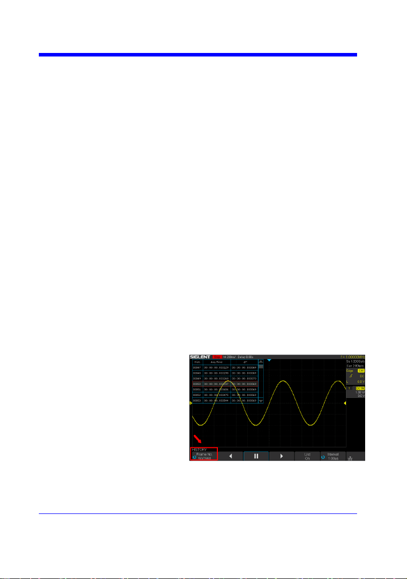
EXAMPLE
When the history function is on, the following
command sets current frame number to 50. Then
you can see the response on the screen as shown
below.
Command message:
FRAM 50

Digital Oscilloscope Series
76
HISTORY
FRAME_TIME? | FTIM?
Query
DESCRIPTION
The FRAME_TIME query returns the acquire
timestamp of the current frame.
QUERY SYNTAX
FTIM?
RESPONSE FORMAT
Format 1:
FTIM hour: minute: second. micro-second
Format 2:
\xFF\x0F\x03\x01&\xD5\x02\x00
Note:
• Format 2 is binary data and has no key word.
• The table below shows the available response
format in each oscilloscope series.
EXAMPLE
For the SDS1000X-E series, when the history
function is on, the following query returns the
acquire time of the current frame.
Query message:
FTIM?
Response message:
FTIM 00: 05: 12. 650814
Format in Each Oscilloscope Series
Model
Response Format
SDS1000CFL
Format 2
SDS1000A
Format 2
SDS1000CML+/CNL+/DL+/E+/F+
Format 2
SDS2000X
Format 2
SDS1000X
Format 2
SDS1000X-E
Format 1

Digital Oscilloscope Series
77
HISTORY
HISTORY_MODE | HSMD
Command/ Query
DESCRIPTION
The HISTORY_MODE command is used to set
the state of history mode.
The HISTORY_MODE? query returns the
current state of history mode.
COMMAND SYNTAX
HSMD <state>
<state>:={ON,OFF}
QUERY SYNTAX
HSMD?
RESPONSE FORMAT
HSMD <state>
EXAMPLE
The following command sets the state of history
mode to ON.
Command message:
HSMD ON
Note:
The table below shows the availability of command in each oscilloscope series.
Model
Valid?
SDS1000CFL
no
SDS1000A
no
SDS1000CML+/CNL+/DL+/E+/F+
no
SDS2000X
no
SDS1000X
no
SDS1000X-E
yes

Digital Oscilloscope Series
78
HISTORY
HISTORY_LIST | HSLST
Command/ Query
DESCRIPTION
The HISTORY_LIST command is used to set
the state of history list.
The HISTORY_LIST? query returns the current
state of history list.
COMMAND SYNTAX
HSLST <state>
<state>:={ON,OFF}
Note:
This command can only be used when History
function is turned on.
QUERY SYNTAX
HSLST?
RESPONSE FORMAT
HSLST <state>
EXAMPLE
When History function is on, the following
command sets the state of history list to ON.
Command message:
HSLST ON
RELATED COMMANDS
HSMD
Note:
The table below shows the availability of command in each oscilloscope series.
Model
Valid?
SDS1000CFL/CML /CNL/DL
no
SDS1000CML+/CNL+/DL+/E+/F+
no
SDS1000A
no
SDS2000X
no
SDS1000X
no
SDS1000X-E
yes

Digital Oscilloscope Series
79
MATH Commands
The MATH subsystem controls the math functions in the oscilloscope. As
selected by the DEF command, these math functions are available:
Operators: Add, Subtract, Multiply, Divide.
Operators perform their function on two analog channel sources.
Transforms: DIFF, Integrate, FFT, SQRT.
DEF
INVS
MTVD
MTVP
FFTC
FFTF
FFTP
FFTS
FFTT?
FFTU
FFTW

Digital Oscilloscope Series
80
MATH
DEFINE | DEF
Command /Query
DESCRIPTION
The DEFINE command sets the desired
waveform math operation.
The DEFINE? query returns the current
operation for the selected function.
COMMAND SYNTAX
DEFINE EQN,‘<equation>‘
Note:
<equation> is the mathematical expression,
enclosed by single or double quotation marks.
Function Equations
<source1> + <source2>
Addition
<source1> - <source2>
Subtraction
<source1>*<source2>
Multiplicatio
n
<source1>/<source2>
Ratio
FFT<source>
FFT
INTG<source>
Integral
DIFF<source>
Differentiato
r
SQRT<source>
Square Root
<source>:={C1,C2,C3,C4}
<source1>:={C1,C2,C3,C4}
<source2>:={C1,C2,C3,C4}
QUERY SYNTAX
DEFINE?
RESPONSE FORMAT
DEFINE EQN,‘<equation>‘
EXAMPLE
• When the Math function is on, and both
Channel 1 and Channel 2 are on, the following
command sets the math operation to
Multiplication, source1 to C1, source2 to C2.
Command message:
DEFINE EQN,’C1*C2’
• When the Math function is on, and Channel 1

Digital Oscilloscope Series
81
is on, the following command sets the math
operation to Differentiator, source to C1.
Command message:
DEFINE EQN,’DIFFC1’

Digital Oscilloscope Series
82
MATH
INVERTSET | INVS
Command/Query
DESCRIPTION
The INVERTSET command inverts the math
waveform.
The INVERTSET? query returns whether the
math waveform is inverted or not.
Note:
This command is only valid in add, subtract,
multiply and divide operation.
COMMAND SYNTAX
<trace>:INVERTSET <state>
<trace>:={MATH}
<state>:= {ON,OFF}
QUERY SYNTAX
<trace>:INVERTSET?
RESPONSE FORMAT
<trace>:INVERTSET <state>
EXAMPLE
When the Math function is on, and the operation
is Add, the following command inverts the math
waveform.
Command message:
MATH:INVS ON
Digital Oscilloscope Series
83
MATH
MATH_VERT_DIV | MTVD
Command/Query
DESCRIPTION
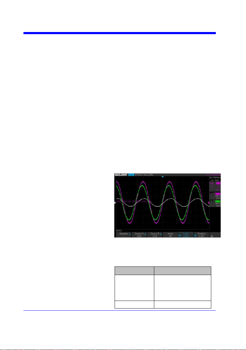
The MATH_VERT_DIV command sets the
vertical scale of the selected math operation.
This command is only valid in add, subtract,
multiply and divide operation.
The MATH_VERT_DIV? query returns the
current scale value for the selected operation.
COMMAND SYNTAX
MATH_VERT_DIV <scale>
<scale>:={500uV,1mV,2mV,5mV,10mV,20mV,
50mV,100mV,200mV,500mV,1V,2V,5V,10V,2
0V ,50V,100V}(for add, subtract, multiply and
divide)
Note:
Legal values for the scale depend on the selected
operation. For details, please refer to the math
menu of the oscilloscope as shown below.
QUERY SYNTAX
MATH_VERT_DIV?
RESPONSE FORMAT
MATH_VERT_DIV <scale>
Model
Format of <scale>
SDS1000X-
E
Numerical value
in E-notation with
SI unit, such as
5.00E-01V.
others
Numerical value

Digital Oscilloscope Series
84
with measurement
unit and physical
unit, such as 500mV.
EXAMPLE
When the Math function is on, and the operator
is Add, the following command changes the
vertical scale of the math waveform to 1 V.
Command message:
MTVD 1V

Digital Oscilloscope Series
85
MATH
MATH_VERT_POS | MTVP
Command/Query
DESCRIPTION
The MATH_VERT_POS command sets the
vertical position of the math waveform with
specified source.
The FFT waveform isn‘t included, but we have
another command which called FFTP to set
vertical position.
The MATH_VERT_POS? query returns the
vertical position of the math waveform.
COMMAND SYNTAX
MATH_VERT_POS <point>
<point>:= -255 to 255.
Note:
The point represents the screen pixels and is
related to the screen center. For example, if the
point is 50. The math waveform will be
displayed 1 grid above the vertical center of the
screen. Namely one grid is 50.
QUERY SYNTAX
MATH_VERT_POS?
RESPONSE FORMAT
MATH_VERT_POS <point>
EXAMPLE
When the Math function is on, the following
command sets the vertical position of the math
waveform to 1 grid above the screen vertical
center.
Command message:
MTVP 50
RELATED COMMANDS
FFTP
Digital Oscilloscope Series
86
MATH
FFT_CENTER | FFTC
Command /Query
DESCRIPTION
The FFT_CENTER command sets the center
frequency when FFT (Fast Fourier Transform) is
selected.
The FFT_CENTER? query returns the current
center frequency of FFT waveform.
COMMAND SYNTAX
FFT_CENTER <center>
<center>:= frequency value with unit (MHz/
kHz/ Hz).
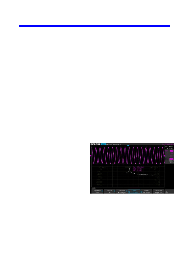
Note:
• If you set the center to a value outside of the
legal range, the center value is automatically set
to the nearest legal value. Legal values are
affected by the Hz/div setting.
• The range for center is related to the
horizontal scale of FFT and varied by models.
See the math menu of oscilloscope as shown
below for details.
QUERY SYNTAX
FFT_CENTER?
RESPONSE FORMAT
FFT_CENTER <center>
EXAMPLE
When the Math function is on, the operator is
FFT, and the horizontal scale is 100 MHz, the
following command sets the center frequency of
FFT to 58 MHz.
Command message:
FFTC 58MHz


Digital Oscilloscope Series
88
MATH
FFT_FULLSCREEN | FFTF
Command /Query
DESCRIPTION
The FFT_FULLSCREEN command sets the
display mode of FFT waveform.
The FFT_FULLSCREEN? query returns
whether the FFT waveform is full screen
displayed.
COMMAND SYNTAX
FFT_FULLSCREEN <state>
<state>:= {OFF,ON, EXCLU}
• OFF — Split Screen.
• ON — Full Screen.
• EXCLU — Exclusive.
QUERY SYNTAX
FFT_FULLSCREEN?
RESPONSE FORMAT
FFT_FULLSCREEN <state>
EXAMPLE
When the Math function is on, and the operator
is FFT, the following command sets the display
mode of FFT waveform to Full Screen.
Command message:
FFTF ON

Digital Oscilloscope Series
89
MATH
FFT_POSITION | FFTP
Command /Query
DESCRIPTION
The FFT_POSITION command sets the vertical
offset of FFT waveform. The unit is related to
the vertical scale type of the current FFT and the
unit of the channel.
The FFT_POSITION? query returns the current
vertical offset of the FFT waveform.
Note:
• This command is only valid when the scale
type is Vrms.
COMMAND SYNTAX
FFT_POSITION <offset>
<offset>:= -24.4*DIV to 15.6*DIV.
Note:
• If there is no unit (V/mV/uV) added, it
defaults to volts (V).
• If you set the offset to a value outside of the
legal range, the center value is automatically set
to the nearest legal value. Legal values are
affected by the Scale setting.
QUERY SYNTAX
FFT_POSITION?
RESPONSE FORMAT
FFT_POSITION <offset>
<offset>:= Numerical value in E-notation with
SI unit.
EXAMPLE
• When the Math function is on, the operator is
FFT, and the scale is 10 mV, the following steps
set the offset of FFT waveform to 28 mV.
Step 1: Send command to set the scale unit to
Vrms.
Command message:
FFTU VRMS
Step 2: Send command to set the offset to 28

Digital Oscilloscope Series
90
mV.
Command message:
FFTP 28mV
• When the Math function is on, the operator is
FFT, and the scale is 5 V, the following steps set
the offset of FFT waveform to -13.5 V.
Step 1: Send command to set the scale unit to
Vrms.
Command message:
FFTU VRMS
Step 2: Send command to set the offset to -13.5
V.
Command message:
FFTP -13.5V
RELATED COMMANDS
FFTS
FFTU
Note:
The table below shows the availability of command in each oscilloscope series.
Model
Valid?
SDS1000CFL
no
SDS1000A
no
SDS1000CML+/CNL+/DL+/E+/F+
no
SDS2000X
no
SDS1000X
no
SDS1000X-E
yes

Digital Oscilloscope Series
91
MATH
FFT_SCALE | FFTS
Command /Query
DESCRIPTION
The FFT_SCALE command sets the vertical
scale of FFT waveform. The unit is related to the
vertical scale type of the current FFT and the
unit of the channel.
The FFT_SCALE? query returns the current
vertical scale of FFT waveform.
COMMAND SYNTAX
FFT_SCALE <scale>
<scale>:={0.1,0.2,0.5,1,2,5,10,20} when scale
type is dBVrms or dBm.
<scale>:={0.001,0.002,0.005,0.01,0.02,0.05,0.1,
0. 2,0.5,1, 2,5,10,20} when scale type is Vrms.
QUERY SYNTAX
FFT_SCALE?
RESPONSE FORMAT
FFT_SCALE <scale>
<scale>:= Numerical value in E-notation with
SI unit.
EXAMPLE
• When the Math function is on, and the
operator is FFT, the following steps set the
vertical scale of FFT to 5 dBVrms.
Step 1: Send command to set the scale unit to
dBVrms.
Command message:
FFTU DBVRMS
Step 2: Send command to set the scale to 5.
Command message:
FFTS 5
• When the Math function is on, and the
operator is FFT, the following steps set the
vertical scale of FFT to 100 mVrms.
Step 1: Send command to set the scale unit to
Vrms.


Digital Oscilloscope Series
93
MATH
FFT_TDIV? | FFTT?
Query
DESCRIPTION
The FFT_TDIV? query returns current
horizontal scale of FFT waveform.
QUERY SYNTAX
FFT_TDIV?
RESPONSE FORMAT
FFT_TDIV <value>
<value>:= Numerical value with
measurement unit and physical unit.
EXAMPLE
The following query returns the horizontal scale
unit of FFT.
Query message:
FFTT?
Response message:
FFTT 100.00MHz
Note:
The table below shows the availability of command in each oscilloscope series.
Model
Valid?
SDS1000CFL
no
SDS1000A
no
SDS1000CML+/CNL+/DL+/E+/F+
no
SDS2000X
no
SDS1000X
no
SDS1000X-E
yes

Digital Oscilloscope Series
94
MATH
FFT_UNIT | FFTU
Command /Query
DESCRIPTION
The FFT_UNIT command sets the vertical scale
type of FFT (Fast Fourier Transform algorithm).
The FFT_UNIT? query returns the current
vertical scale type of FFT waveform.
COMMAND SYNTAX
FFT_UNIT <unit>
<unit>:={VRMS,DBM,DBVRMS}
QUERY SYNTAX
FFT_UNIT?
RESPONSE FORMAT
FFT_ UNIT <unit>
EXAMPLE
For SDS1000X-E series, when the Math
function is on, and the operator is FFT, the
following command sets the vertical scale unit of
FFT to dBVrms.
Command message:
FFTU DBVRMS
RELATED COMMANDS
FFTS
FFTP
Note:
The table below shows the availability of command in each oscilloscope series.
Model
Valid?
SDS1000CFL
no
SDS1000A
no
SDS1000CML+/CNL+/DL+/E+/F+
no
SDS2000X
no
SDS1000X
no
SDS1000X-E
yes

Digital Oscilloscope Series
95
MATH
FFT_WINDOW | FFTW
Command /Query
DESCRIPTION
The FFT_WINDOW command allows the
selection of five different windowing transforms
or operations for the FFT (Fast Fourier
Transform) function. Each window is useful for
certain classes of input signals.
The FFT_WINDOW? query returns the current
window of FFT.
COMMAND SYNTAX
FFT_WINDOW <window>
<window>:={RECT,BLAC,HANN,HAMM,FL
ATTOP}
• RECT — Rectangle is useful for transient
signals, and signals where there are an integral
number of cycles in the time record.
• BLAC — Blackman reduces time resolution
compared to the rectangular window, but it
improves the capacity to detect smaller impulses
due to lower secondary lobes (provides minimal
spectral leakage).
• HANN — Hanning is useful for frequency
resolution and general purpose use. It is good for
resolving two frequencies that are close together,
or for making frequency measurements.
• HAMM — Hamming.
• FLAT — Flattop is the best for making
accurate amplitude measurements of frequency
peaks.
QUERY SYNTAX
FFT_WINDOW?
RESPONSE FORMAT
FFT_WINDOW <window>
EXAMPLE
When the Math function is on, and the operator
is FFT, the following command sets the FFT
window to Hamming.
Command message:
FFTW HAMM

Digital Oscilloscope Series
96
MEASURE Commands
The commands in the MEASURE subsystem are used to make parametric
measurements on displayed waveforms.
To make a measurement, the portion of the waveform required for that
measurement must be displayed on the oscilloscope screen.
CYMT?
MEAD
PACU
PAVA?
Digital Oscilloscope Series
97
MEASURE
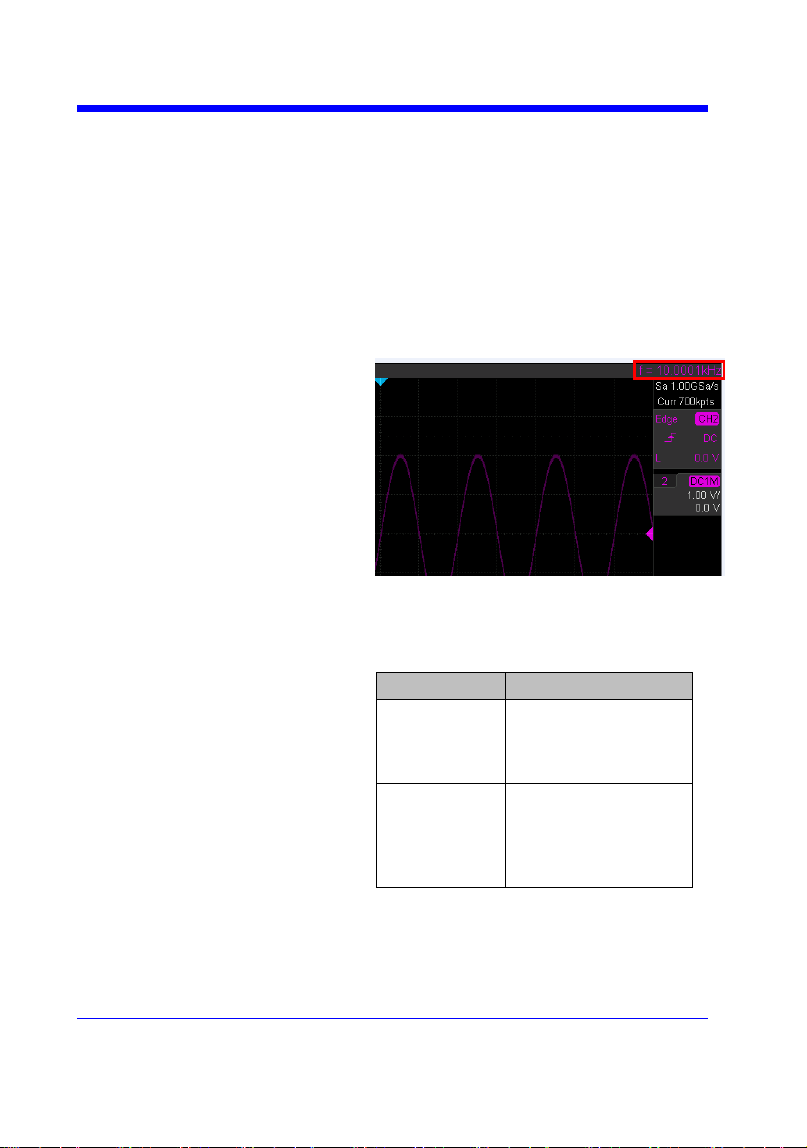
CYMOMETER? | CYMT?
Query
DESCRIPTION
The CYMOMETER? query measures and
returns the frequency counter of the specified
source. The counter measurement counts the
trigger level crossings at the selected trigger
slope and displays the results in MHz/kHz/Hz.
In the following picture, the content of the red
box is the measured value of the cymometer.
QUERY SYNTAX
CYMOMETER?
RESPONSE FORMAT
CYMOMETER <freq>
Model
Format of <freq>
SDS1000X-
E
Numerical value
in E-notation with
SI unit, such as
1.00E+03Hz.
others
Numerical value
with measurement
unit and physical
unit, such as
1.00001kHz.
Note:
When the signal frequency is less than 10 Hz, it
returns ―10 Hz‖ or ―<10Hz‖.
EXAMPLE
• When the frequency of input signal is l Hz, the

Digital Oscilloscope Series
98
following returns the value of cymometer which
displaying on the screen of the instrument.
Response message:
CYMT 10Hz
• When the frequency of input signal is
25.000137 MHz, the following returns the value
of cymometer which displaying on the screen of
the instrument.
Response message:
CYMT 2.50E+07Hz
Digital Oscilloscope Series
99
MEASURE
MEASURE_DELAY | MEAD
Command/Query
DESCRIPTION
The MEASURE_DELY command places the
instrument in the continuous measurement mode
and starts a type of delay measurement.
The MEASURE_DELY? query returns the
measured value of delay type.
COMMAND SYNTAX
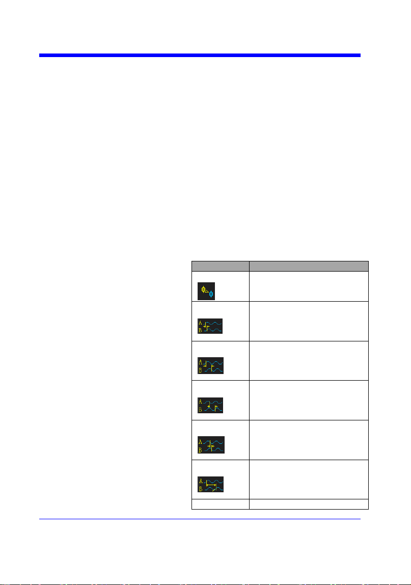
MEASURE_DELAY <type>,<sourceA-
sourceB>
<sourceA-sourceB>:={C1-C2,C1-C3,C1-C4,C2-
C3,C2-C4,C3-C4}
<type>:={PHA,FRR,FRF,FFR,FFF,LRR,LRF,L
FR,LFF,SKEW}
Type
Description
PHA
The phase difference
between two channels.
(rising edge - rising edge)
FRR
Delay between two
channels.
(first rising edge - first
rising edge)
FRF
Delay between two
channels.
(first rising edge - first
falling edge)
FFR
Delay between two
channels.
(first falling edge - first
rising edge)
FFF
Delay between two
channels.
(first falling edge - first
falling edge)
LRR
Delay between two
channels.
(first rising edge - last rising
edge)
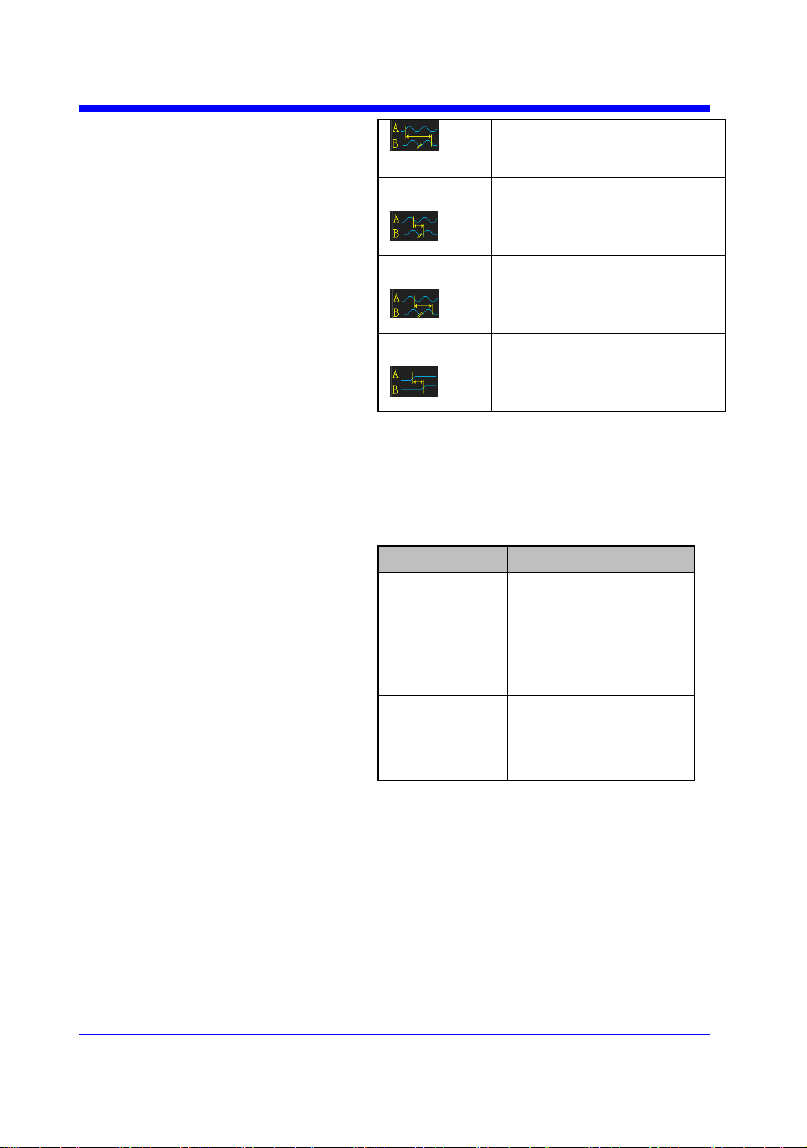
LRF
Delay between two
Digital Oscilloscope Series
100
channels.
(first rising edge - last
falling edge)
LFR
Delay between two
channels.
(first falling edge - last
rising edge)
LFF
Delay between two
channels.
(first falling edge - last
falling edge)
Skew
Delay between two
channels.
(edge – edge of the same
type)
QUERY SYNTAX
<sourceA-sourceB>:MEASURE_DELY?
<type>
RESPONSE FORMAT
<sourceA-sourceB>:MEAD <type>,<value>
Model
Format of <value>
SDS1000X-
E
Numerical value
in E-notation with
SI unit, such as
1.24E-04S. Except
for PHA, it returns
as ―44.65degree‖.
others
Numerical value
in E-notation with
SI unit, such as
2.06E+01degree.
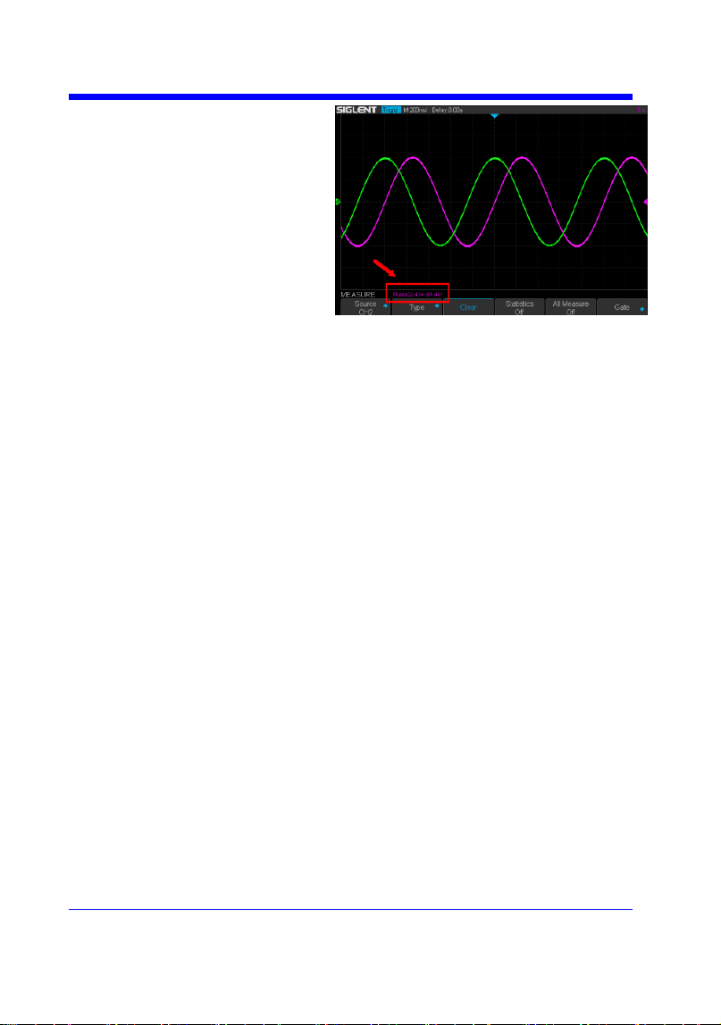
EXAMPLE
The following steps show how to get the
measured value of phase between C2 and C4.
Step 1: Send the message to set the
measurement to Phase between C2 and C4, and
then there displays a phase measurement on the
screen.
Command message:
MEAD PHA,C2-C4
Digital Oscilloscope Series
101
Step 2: Send the message to get the measured
value of phase.
Command message:
C2-C4:MEAD? PHA
Response message:
C2-C4:MEAD PHA,-89.46degree

Digital Oscilloscope Series
102
MEASURE
PARAMETER_CUSTOM | PACU
Command
DESCRIPTION
The PARAMETER_CUSTOM command
installs a measurement and starts the specified
measurement of the specified source.
See the command PAVA? to get the measured
value of specified measurement.
See the command MEAD to install the
measurement of delay class.
COMMAND SYNTAX
PARAMETER_CUSTOM
<parameter>,<source>
<source>:= {C1,C2,C3,C4}
<parameter>:={PKPK,MAX,MIN,AMPL,TOP,
BASE,CMEAN,MEAN,RMS,CRMS,OVSN,FP
RE,OVSP,RPRE,PER,FREQ,PWID,NWID,RIS
E,FALL,WID,DUTY,NDUTY,ALL}
Description of Parameter
Parameter
Description
PKPK
vertical peak-to-peak
MAX
maximum vertical value
MIN
minimum vertical value
AMPL
vertical amplitude
TOP
waveform top value
BASE
waveform base value
CMEAN
average value in the first
cycle
MEAN
average value
RMS
RMS value
CRMS
RMS value in the first
cycle
OVSN
overshoot of a falling
edge
FPRE
preshoot of a falling edge
OVSP
overshoot of a rising edge
RPRE
preshoot of a rising edge
PER
period
FREQ
frequency
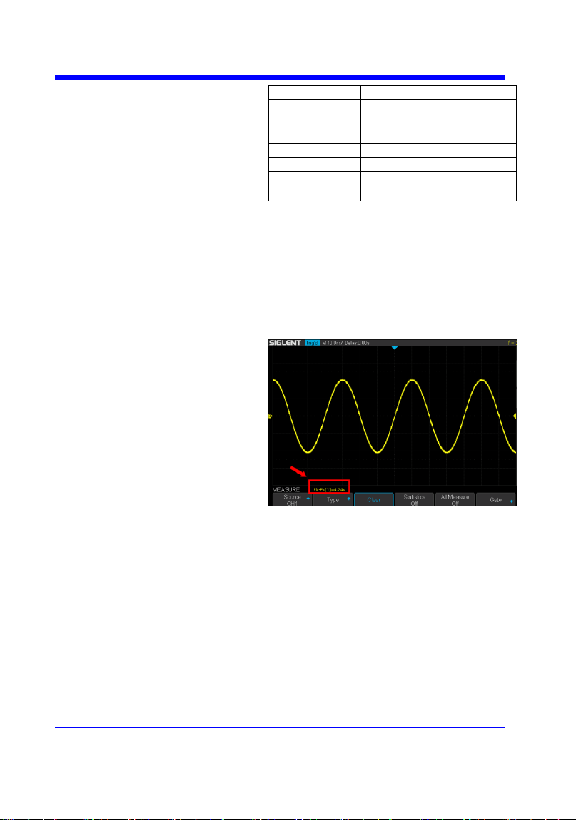
Digital Oscilloscope Series
103
PWID
positive pulse width
NWID
negative pulse width
RISE
rise-time
FALL
fall-time
WID
Burst width
DUTY
positive duty cycle
NDUTY
negative duty cycle
ALL
All measurement
EXAMPLE
• The following command sets the type of
measure to PKPK of Channel 1. Command
message:
PACU PKPK,C1
Then, you can see the measurement on the
screen.
• The following command sets the type of
measure to ALL of Channel 2. Command
message:
PACU ALL,C2
Then, you can see a snapshot of all
measurements on the screen.
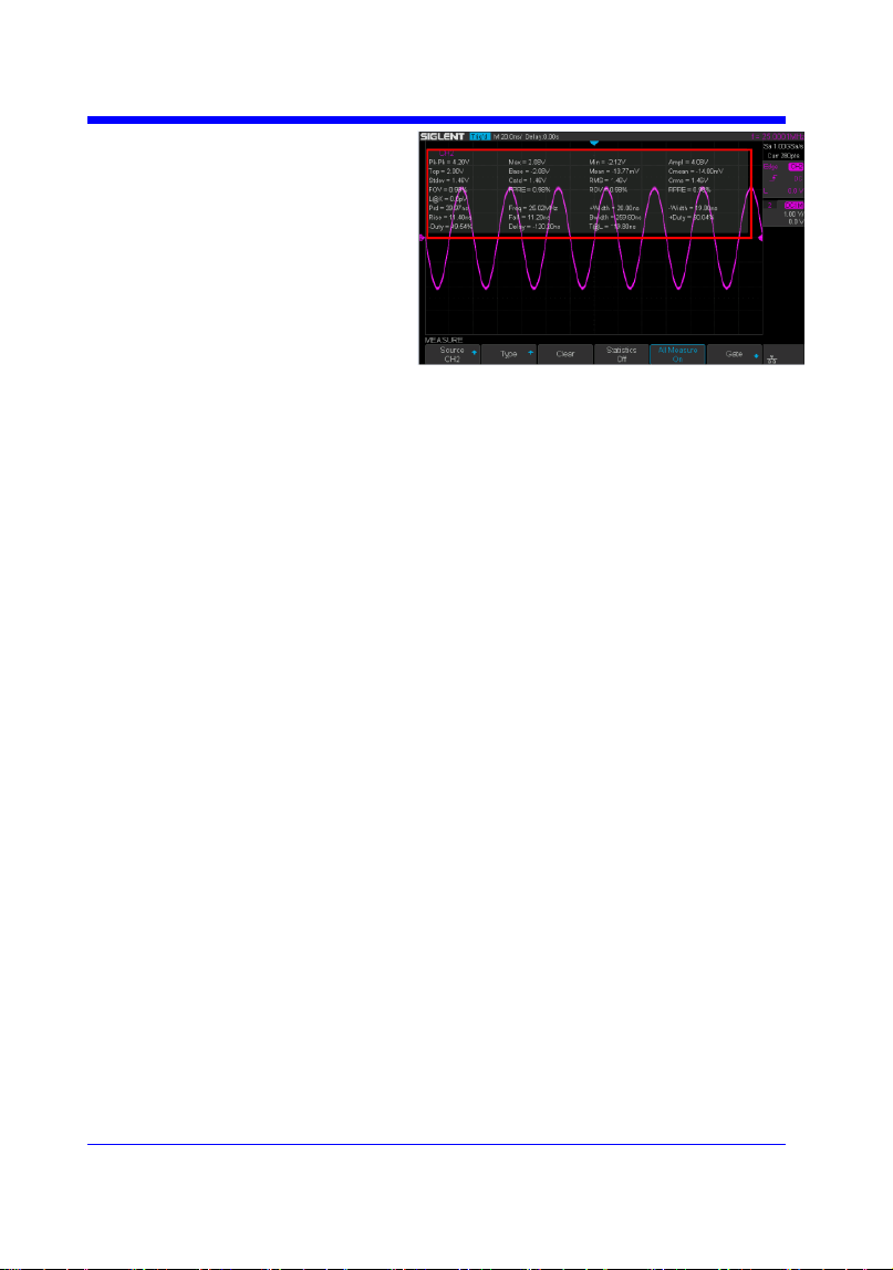

Digital Oscilloscope Series
105
MEASURE
PARAMETER_VALUE? | PAVA?
Query
DESCRIPTION
The PARAMETER_VALUE query measures
and returns the specified measurement value
present on the selected waveform.
There are three uses for this command:
Usage
Description
Usage1
Specify the source and the
measurement.
See the command ―MEAD?‖
to get the measured value of
delay measurement.
Usage 2
Use ―PAVA? CUST<x>‖ to
get customized.
Usage 3
Use ―PAVA? STAT<x>‖ to
get statistics.
QUERY SYNTAX
Usage 1
<source>:PARAMETER_VALUE?
<parameter>
<source>:= {C1,C2,C3,C4}
<parameter>:={PKPK,MAX,MIN,AMPL,TOP,
BASE,CMEAN,MEAN,RMS,CRMS,OVSN,FP
RE,OVSP,RPRE,PER,FREQ,PWID,NWID,RIS
E,FALL,WID,DUTY,NDUTY,ALL}
See the table Description of Parameter for
details.
RESPONSE FORMAT
<source>:PARAMETER_VALUE
<parameter>,<value>
<value>:= Numerical value in E-notation with
SI unit.
QUERY SYNTAX
Usage 2
PARAMETER_VALUE? CUST<x>
<x>:= 1 to 5, and ALL
Custom
Description

Digital Oscilloscope Series
106
Parameters
CUST1
The first measure
parameter specified by
―PACU‖
CUST2
The second measure
parameter specified by
―PACU‖
CUST3
The third measure
parameter specified by
―PACU‖
CUST4
The fourth measure
parameter specified by
―PACU‖
CUST5
The fifth measure
parameter specified by
―PACU‖
CUSTALL
All measure parameters
specified by ―PACU‖
Note:
• Installing the measurement as CUST<x> by
using command ―PACU‖, before using usage 2.
• When the number of installed measurements
is less than 5 and you send the command
―PAVA? CUSTALL‖, it will return OFF as
value for remaining custom parameters.
RESPONSE FORMAT
PARAMETER_VALUE
CUST<x>:<source>,<parameter>,<value>
<value>:= Numerical value in E-notation with
SI unit.
QUERY SYNTAX
Usage 3
PARAMETER_VALUE? STAT<x>
<x>:= 1 to 5
Custom
Parameters
Description
STAT1
Statistics of the first
measure parameter
specified by ―PACU‖
STAT2
Statistics of the second
measure parameter
specified by ―PACU‖
STAT3
Statistics of the third
measure parameter

Digital Oscilloscope Series
107
specified by ―PACU‖
STAT4
Statistics of the fourth
measure parameter
specified by ―PACU‖
STAT5
Statistics of the fifth
measure parameter
specified by ―PACU‖
Note:
Installing the statistics of the measurement as
STAT<x> by using command ―PACU‖, before
using usage 3.
RESPONSE FORMAT
PARAMETER_VALUE STAT<x> <source>
<parameter>:cur,<value1>,mean,<value2>,min,
<value3>,max,<value4>,std-
dev,<value5>,count,<value6>
Parameter
Description
cur
Current value of
measurement
mean
Mean value of
measurement
min
Minimum value of
measurement
max
Maximum value of
measurement
std-dev
Standard deviation of
measurement
count
Measurement count
<value>:= Numerical value in E-notation with
SI unit.
EXAMPLE
• The following query returns the rise time of
Channel 2.
Query message:
C2:PAVA? RISE
Response message:
C2:PAVA RISE, 3.6E-9S
• The following query returns all measurement
of Channel 1.

Digital Oscilloscope Series
108
Query message:
C1:PAVA? ALL
Response message:
C1:PAVA MAX,2.04E+00V,MIN,-
2.16E+00V,PKPK,4.20E+00V,TOP,2.00E+00V,
BASE,-2.08E+00V,AMPL,4.08E+00V,MEAN,-
1.95E-02V,CMEAN,-6.30E-
03V,STDEV,1.46E+00V,VSTD,1.46E+00V,RMS,
1.46E+00V,CRMS,1.46E+00V,OVSN,1.96%,FP
RE,0.98%,OVSP,0.98%,RPRE,0.00%,LEVELX,0
.00E+00V,PER,4.00E08S,FREQ,2.50E+07Hz,P
WID,****,NWID,****,RISE,4.29E-
01S,FALL,1.14E-08S,WID,9.99E-
08S,DUTY,****,NDUTY,****,DELAY,-6.01E-
08S,TIMEL,3.97E-08S
• The following steps show how the user
customize the measurement parameters and get
the measured value.
Step 1: Send the command to set the
measurement parameter.
Command message:
PACU PKPK,C1
Step 2: Send the query to get the measured
value.
Query message:
PAVA? CUST1
Response message:
PAVA CUST1:C1,PKPK,4.08E+00V
Step 3: You can also send the query to get the
measured value.
Command message:
PAVA? CUSTALL
Response message:
PAVA
CUST1:C1,PKPK,4.08E+00V;CUST2:OFF;CU
ST3:OFF;CUST4:OFF;CUST5:OFF

Digital Oscilloscope Series
109
• The following steps show how to get the
statistical values of user defined measurement
parameters.
Step 1: Send the command to set the
measurement parameter as the first customized
parameter.
Command message:
PACU FREQ,C3
Step 2: Send the query to get the statistical
values of the first customized parameter.
Query message:
PAVA? STAT1
Response message:
PAVA STAT1 C3
FREQ:cur,1.00E+06Hz,mean,1.00E+06Hz,min,
9.97E+05Hz,max,1.00E+06Hz,std-
dev,1.41E+03Hz,count,171
RELATED COMMANDS
PACU
MEAD


Digital Oscilloscope Series
112
PASS/FAIL
PF_BUFFER | PFBF
Command/Query
DESCRIPTION
The PF_BUFFER command sets the output
mode when the test fails. This is the same as
pressing the ―Output‖ button on the menu of
PASS/FAIL on the front panel.
The PF_BUFFER? query returns the current
output mode of the pass/fail.
COMMAND SYNTAX
PF_BUFFER <state>
<state>:= {ON,OFF}
• ON — The statistical result is displayed when
the failed waveform is detected, and the buzzer
alarm. (not related to the state of the sound
switch)
• OFF — The statistical result is displayed
when the failed waveform is detected, but the
buzzer does not alarm.
QUERY SYNTAX
PF_BUFFER?
RESPONSE FORMAT
PF_BUFFER <state>
EXAMPLE
When the PASS/FAIL function is on, the
following command sets ―output‖ to ―ON‖.
Command message:
PFBF ON
Note:
The table below shows the availability of command in each oscilloscope series.
Model
Valid?
SDS1000CFL
no
SDS1000A
no
SDS1000CML+/CNL+/DL+/E+/F+
no
SDS2000X
no
SDS1000X
no
SDS1000X-E
yes

Digital Oscilloscope Series
113
PASS/FAIL
PF_CREATEM | PFCM
Command
DESCRIPTION
The PF_CREATEM command creates a pass/
fail test rule around the current selected channel,
using the horizontal adjustment parameters and
the vertical adjustment parameters defined by the
PFST commands.
Note:
This command is valid only if the pass / fail test
function has been opened (PFEN) and is not in
operation (PFOP).
COMMAND SYNTAX
PF_ CREATEM
EXAMPLE
The following steps create the mask of the
pass/fail.
Step 1: Send command to set the Pass/Fail test
enable.
Command message:
PFEN ON
Step 2: Send command to stop the operation.
Command message:
PFOP OFF
Step 3: Send command to create the rule.
Command message:
PFCM
RELATED COMMANDS
PFST
PFSC
PFEN
PFOP

Digital Oscilloscope Series
114
PASS/FAIL
PF_DATADIS? | PFDD?
Query
DESCRIPTION
The PF_DATADIS? query returns the number of
the failed frames, passed frames and total frames
which are shown on screen.
COMMAND SYNTAX
PF_ DATADIS?
RESPONSE FORMAT
PF_DATADIS
FAIL,<num>,PASS,<num>,TOTAL,<num>
EXAMPLE
The following query returns the number of the
message display of the pass/fail.
Query message:
PFDD?
Response message:
PFDD FAIL,0,PASS,0,TOTAL,0

Digital Oscilloscope Series
115
PASS/FAIL
PF_DISPLAY | PFDS
Command /Query
DESCRIPTION
The PF_DISPLAY command displays
information in Pass/Fail test features.
The PF_DISPLAY? query returns whether the
message of Pass/Fail is displayed.
COMMAND SYNTAX
PF_DISPLAY <state>
<state>:={ON,OFF}
QUERY SYNTAX
PF_DISPLAY?
RESPONSE FORMAT
PF_DISPLAY <state>
EXAMPL
The following steps display the message of
Pass/Fail.
Step 1: Send command to set the Pass/Fail test
enable.
Command message:
PFEN ON
Step 2: Send command to display the message
of Pass/Fail.
Command message:
PFDS ON
RELATED COMMANDS
PFEN

Digital Oscilloscope Series
116
PASS/FAIL
PF_ENABLE | PFEN
Command /Query
DESCRIPTION
The PF_ENABLE command enables or disables
the Pass/Fail test features.
The PF_ENABLE? query returns the current
state of mask test features.
COMMAND SYNTAX
PF_ENABLE <state>
<state>:= {ON,OFF}
• ON — Enables the mask test features.
• OFF — Disables the mask test features.
QUERY SYNTAX
PF_ENABLE?
RESPONSE FORMAT
PF_ENABLE <state>
EXAMPL
The following command enables mask test
features.
Command message:
PFEN ON
Note:
The table below shows the availability of command in each oscilloscope series.
Model
Valid?
SDS1000CFL
no
SDS1000A
no
SDS1000CML+/CNL+/DL+/E+/F+
no
SDS2000X
no
SDS1000X
no
SDS1000X-E
yes

Digital Oscilloscope Series
117
PASS/FAIL
PF_FAIL_STOP | PFFS
Command/Query
DESCRIPTION
The PF_FAIL_STOP command sets the switch
of the ―stop on fail‖ function. This is the same as
pressing the ―Stop on Fail‖ button on the menu
of PASS/FAIL on the front panel.
The PF_FAIL_STOP? query returns the state of
the ―stop on fail‖ function.
COMMAND SYNTAX
PF_FAIL_STOP <state>
<state>:={ON,OFF}
• ON — To monitor the failure waveform, the
oscilloscope stops testing and enters the "STOP"
state. At this point, the screen displays the last
statistical result.(if the display is already open)
• OFF — To monitor the failure waveform, the
oscilloscope will continue to test and update the
statistics on the screen immediately.
QUERY SYNTAX
PF_FAIL_STOP?
RESPONSE FORMAT
PF_FAIL_STOP <state>
EXAMPLE
The following command sets ―stop on fail‖ to
―off‖.
Command message:
PFFS OFF
Note:
The table below shows the availability of command in each oscilloscope series.
Model
Valid?
SDS1000CFL
no
SDS1000A
no
SDS1000CML+/CNL+/DL+/E+/F+
no
SDS2000X
no

Digital Oscilloscope Series
118
SDS1000X
no
SDS1000X-E
yes

Digital Oscilloscope Series
119
PASS/FAIL
PF_OPERATION | PFOP
Command/Query
DESCRIPTION
The PF_OPERATION command controls to run
or stop Pass/Fail test.
The PF_OPERATION? query returns the
operation state of Pass/Fail test.
COMMAND SYNTAX
PF_OPERATION <state>
<state>:={ON,OFF}
QUERY SYNTAX
PF_OPERATION?
RESPONSE FORMAT
PF_OPERATION <state>
EXAMPLE
The following command controls to run
Pass/Fail test.
Command message:
PFOP ON
RELATED COMMANDS
PFEN
Note:
The table below shows the availability of command in each oscilloscope series.
Model
Valid?
SDS1000CFL
no
SDS1000A
no
SDS1000CML+/CNL+/DL+/E+/F+
no
SDS2000X
no
SDS1000X
no
SDS1000X-E
yes

Digital Oscilloscope Series
120
PASS/FAIL
PF_SOURCE | PFSC
Command/Query
DESCRIPTION
The PF_SOURCE command sets measurement
sources for Pass/Fail test.
The PF_SOURCE? query returns the
measurement source for Pass/Fail test.
COMMAND SYNTAX
PF_SOURCE <trace>
<trace>:={C1,C2,C3,C4}
QUERY SYNTAX
PF_SOURCE?
RESPONSE FORMAT
PF_SOURCE <trace>
EXAMPLE
The following command sets the measurement
source to Channel 1 when Channel 1 is on.
Command message:
PFSC C1
Note:
The table below shows the availability of command in each oscilloscope series.
Model
Valid?
SDS1000CFL
no
SDS1000A
no
SDS1000CML+/CNL+/DL+/E+/F+
no
SDS2000X
no
SDS1000X
no
SDS1000X-E
yes

Digital Oscilloscope Series
121
PASS/FAIL
PF_SET | PFST
Command /Query
DESCRIPTION
The PF_SET command sets the tolerance in the
X/Y direction around the selected waveform
defined by PFSC for the Pass/Fail feature. The
value of the tolerance will be added and
subtracted to horizontal/Vertical values of the
waveform to determine the boundaries of the
mask.
The PF_ SET? query returns the current setting
of the ΔX tolerance and ΔY tolerance for
Pass/Fail.
COMMAND SYNTAX
PF_ SET XMASK,<div>,YMASK,<div>
<div>:= 0.04 to 4.0.
Note:
Step value is 0.04.
QUERY SYNTAX
PF_ SET?
RESPONSE FORMAT
PF_ SET XMASK,<div>,YMASK,<div>
EXAMPLE
The following command sets the X mask to 0.4
and the Y mask to 0.52.
Command message:
PFST XMASK,0.4,YMASK,0.52
RELATED COMMANDS
PFSC

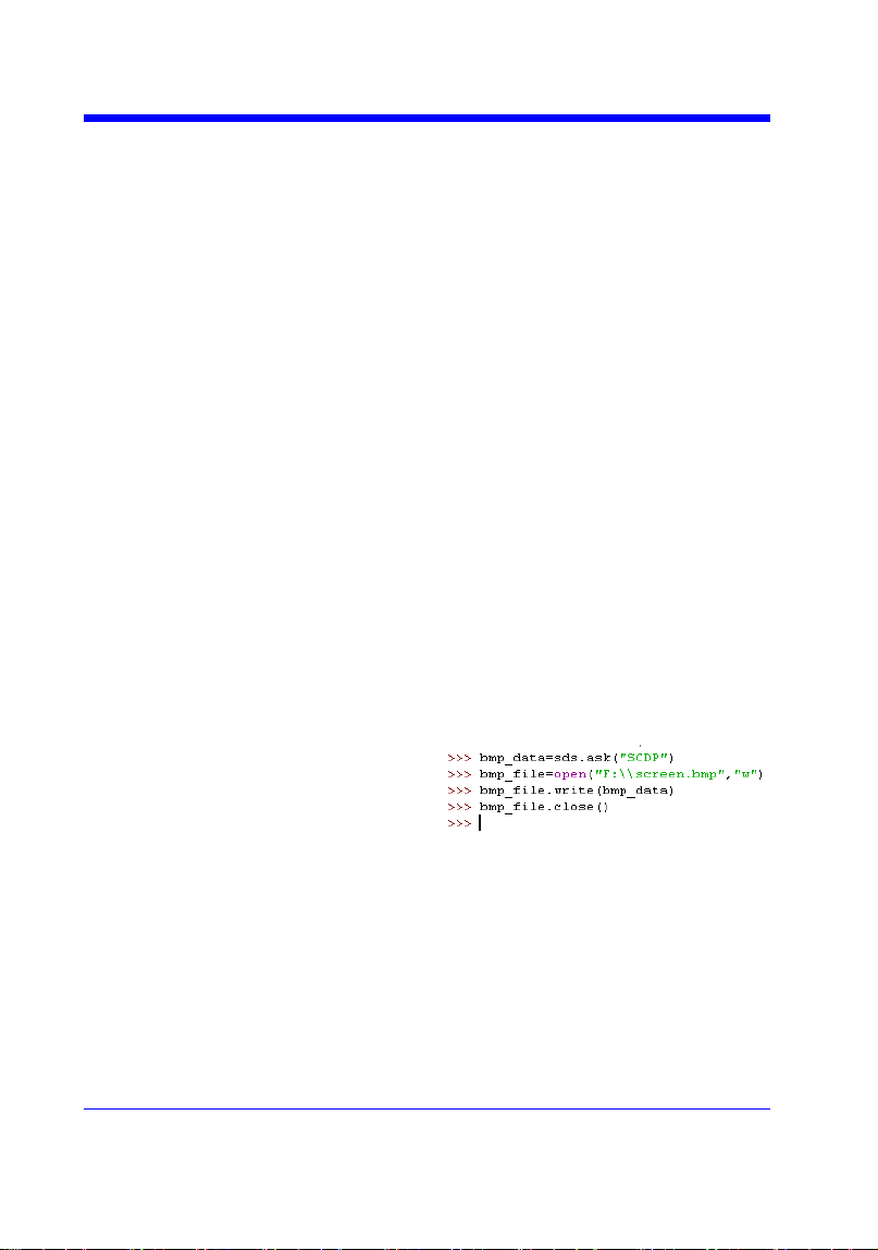
Digital Oscilloscope Series
123
PRINT
SCREEN_DUMP | SCDP
Query
DESCRIPTION
The SCREEN_DUMP command captures
the screen and returns the data of bmp file.
QUERY SYNTAX
SCREEN_DUMP
RESPONSE FORMAT
<bmp header>+<bmp screen data>
Note:
You only need to save the returned
information in a BMP format file.
EXAMPLE
The following step shows how to transfers
the screen information as a file named
screen.bmp in a Python shell.
Step 1: Send the query to get the bmp data.
Query message: SCDP
Step 2: Create a new bmp file named
―screen.bmp‖.
Step 3: Write the data to the file.
Step 4: Close the file.
(See the code in Screen Dump (SCDP)
Example)

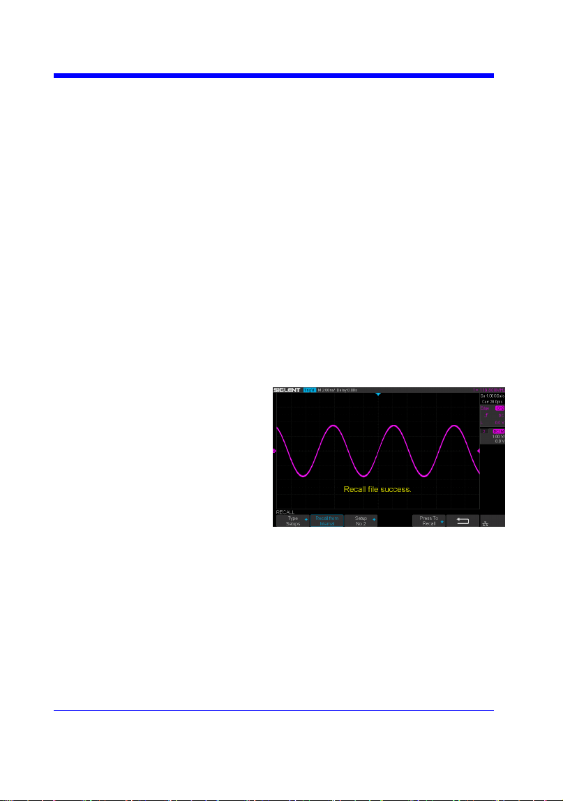
Digital Oscilloscope Series
125
RECALL
*RCL
Command
DESCRIPTION
The *RCL command recalls the complete
front-panel setup of the instrument from
internal memory, using one of the twenty non-
volatile panel setups. This command is
opposite to the command *SAV.
See the command RCPN for recalling the
setup from external.
COMMAND SYNTAX
*RCL <setup_num>
<setup_num>:= 0 to 20.
Note:
• When setup_num is 0, it will recall the
default panel setup.
• As shown below, when the progress is
finished, there will be a prompt message.
EXAMPLE
When you have stored the instrument setup in
No.3, the following command recalls the setup
3.
Command message:
*RCL 3
RELATED COMMANDS
RCPN
*SAV

Digital Oscilloscope Series
126
RECALL
RECALL_PANEL | RCPN
Command
DESCRIPTION
The RECALL_PANEL command recalls a
front-panel setup from the specified-DOS
path directory in an external memory
device.
See the command ―*RCL‖ for recalling
from internal.
COMMAND SYNTAX
RECALL_PANEL
DISK,<device>,FILE,‗<filename>‘
<device>:= {UDSK}
<filename>:= A waveform file under a legal
DOS path.
Models
Description
SDS1000X-E
The filename string is
up to eight characters,
with the extension
―.xml‖.
Others
The filename string is
up to eight characters,
with the extension
―.set‖.
Note:
• See models on page 14.
• For SDS1000X-E series, the ‗/‘ character
to define the root directory is not supported.
• As shown below, when the progress is
finished, there will be a prompt message.
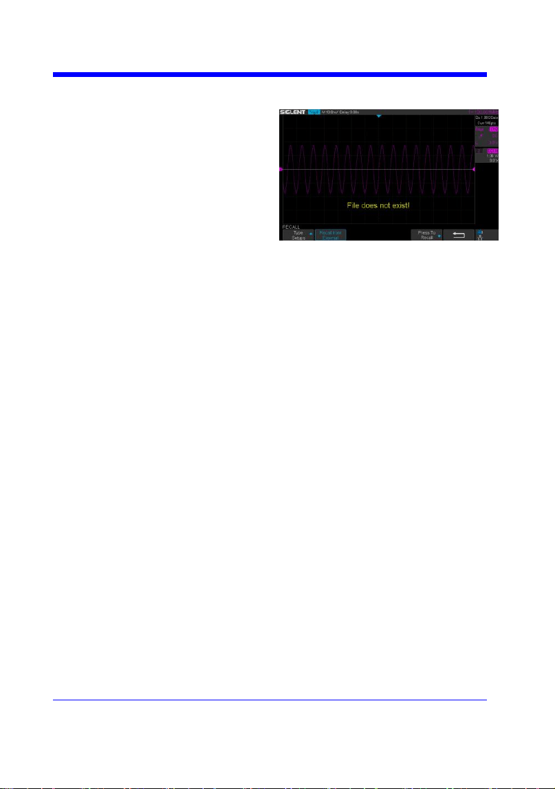
Digital Oscilloscope Series
127
• As shown below, if the filename is
wrong, there will be a prompt message.
EXAMPLE
• For SDS1000X-E series, when you plug
in an U-disk to the oscilloscope, the
following command recalls the front-panel
setup from a file called ―TEST.xml‖ in root
directory of the USB memory device.
Command message:
RCPN DISK,UDSK,FILE,‘TEST.xml’
• For SDS1000X-E series, when you plug
in an U-disk to the oscilloscope, the
following command recalls the front-panel
setup from a file called ―TEST.xml‖ in
specified-directory of the USB memory
device.
Command message:
RCPN
DISK,UDSK,FILE,’/SAVE/TEST.xml’
RELATED COMMANDS
STPN
*RCL


Digital Oscilloscope Series
129
REFERENCE
REF_CLOSE | REFCL
Command
DESCRIPTION
The REF_CLOSE command closes the
Reference function.
COMMAND SYNTAX
REF_CLOSE
EXAMPLE
The following command closes the
Reference function.
Command message:
REFCL
Note:
The table below shows the availability of command in each oscilloscope series.
Model
Valid?
SDS1000CFL
no
SDS1000A
no
SDS1000CML+/CNL+/DL+/E+/F+
no
SDS2000X
no
SDS1000X
no
SDS1000X-E
yes

Digital Oscilloscope Series
130
REFERENCE
REF_DISPLAY | REFDS
Command /Query
DESCRIPTION
The REF_DISPLAY command enables or
disables the current reference channel
shown on the screen.
The REF_DISPLAY? query returns whether
the current reference channel shows on the
screen.
COMMAND SYNTAX
REF_ DISPLAY <state>
<state>:= {ON,OFF}
Note:
Only used when the current reference
channel has been stored, and the Reference
function is enable.
QUERY SYNTAX
REF_ DISPLAY?
RESPONSE FORMAT
REF_ DISPLAY <state>
EXAMPLE
The following command displays the
waveform of the current reference channel.
Command message:
REFDS ON
RELATED COMMANDS
REFCL
Note:
The table below shows the availability of command in each oscilloscope series.
Model
Valid?
SDS1000CFL
no
SDS1000A
no
SDS1000CML+/CNL+/DL+/E+/F+
no
SDS2000X
no
SDS1000X
no
SDS1000X-E
yes

Digital Oscilloscope Series
131
REFERENCE
REF_LOCATION | REFLA
Command /Query
DESCRIPTION
The REF_LOCATION command selects the
current reference channel.
The REF_LOCATION? query returns the
current reference channel.
COMMAND SYNTAX
REF_LOCATION <location>
<location>:= {REFA,REFB,REFC,REFD}
QUERY SYNTAX
REF_LOCATION?
RESPONSE FORMAT
REF_LOCATION <location>
EXAMPLE
The following command selects REFA as
the current reference channel.
Command message:
REFLA REFA
Note:
The table below shows the availability of command in each oscilloscope series.
Model
Valid?
SDS1000CFL
no
SDS1000A
no
SDS1000CML+/CNL+/DL+/E+/F+
no
SDS2000X
no
SDS1000X
no
SDS1000X-E
yes

Digital Oscilloscope Series
132
REFERENCE
REF_POSITION | REFPO
Command /Query
DESCRIPTION
The REF_POSITION command sets the
vertical offset of the current reference
channel. This command is only used when
the current reference channel has been
saved, and the display state is on.
The REF_POSITION? query returns the
vertical offset of the current reference
channel.
COMMAND SYNTAX
REF_ POSITION <offset>
<offset>:= vertical offset value with unit.
Note:
• If there is no unit(V/mV/uV) added, it
defaults to be V.
• The range of legal offset varies with the
value set by the REFSC command. If you
set the offset to a value outside of the legal
range, the offset value is automatically set
to the nearest legal value.
QUERY SYNTAX
REF_ POSITION?
RESPONSE FORMAT
REF_ POSITION <offset>
<offset>:= Numerical value in E-notation
with SI unit.
EXAMPLE
When the Reference function is on, REFB
has been saved and the scale is 2 V, the
following command sets the current
reference channel vertical offset to 0.2 V.
Command message:
REFPO 0.2V
RELATED COMMANDS
REFSC
Note:
The table below shows the availability of command in each oscilloscope series.

Digital Oscilloscope Series
133
Model
Valid?
SDS1000CFL
no
SDS1000A
no
SDS1000CML+/CNL+/DL+/E+/F+
no
SDS2000X
no
SDS1000X
no
SDS1000X-E
yes

Digital Oscilloscope Series
134
REFERENCE
REF_SAVE | REFSA
Command
DESCRIPTION
The REF_SAVE command saves the
waveform (screen range) of the specified
source as the reference waveform of the
current reference channel to the memory
and displays it on the screen.
COMMAND SYNTAX
REF_SAVE
EXAMPLE
When the Reference function is on, the REF
source is Channel 2, and the REF location is
REFA, the following command saves
Channel 2 as REFA and displays REFA on
screen.
Command message:
REFSA
Note:
The table below shows the availability of command in each oscilloscope series.
Model
Valid?
SDS1000CFL
no
SDS1000A
no
SDS1000CML+/CNL+/DL+/E+/F+
no
SDS2000X
no
SDS1000X
no
SDS1000X-E
yes

Digital Oscilloscope Series
135
REFERENCE
REF_SCALE | REFSC
Command /Query
DESCRIPTION
The REF_SCALE command sets the
vertical scale of the current reference
channel. This command is only used when
the current reference channel has been
stored, and the display state is on.
The REF_SCALE? query returns the
vertical scale of the current reference
channel.
COMMAND SYNTAX
REF_ SCALE <scale>
<scale>:= 500uV to 10V.
Note:
If there is no unit(V/mV/uV) added, it
defaults to be V.
QUERY SYNTAX
REF_ SCALE?
RESPONSE FORMAT
REF_ SCALE <scale>
<scale>:= Numerical value in E-notation
with SI unit.
EXAMPLE
When the Reference function is on, and
REFA has been saved, the following
command sets the vertical scale of REFA to
100 mV.
Command message:
REFSC 100mV
Note:
The table below shows the availability of command in each oscilloscope series.
Model
Valid?
SDS1000CFL
no
SDS1000A
no
SDS1000CML+/CNL+/DL+/E+/F+
no
SDS2000X
no

Digital Oscilloscope Series
136
SDS1000X
no
SDS1000X-E
yes

Digital Oscilloscope Series
137
REFERENCE
REF_SOURCE | REFSR
Command /Query
DESCRIPTION
The REF_SOURCE command sets the
reference waveform source.
The REF_SOURCE? query returns the
source of the current reference channel.
COMMAND SYNTAX
REF_SOURCE <source>
<source>:= {C1,C2,C3,C4,MATH}
QUERY SYNTAX
REF_SOURCE?
RESPONSE FORMAT
REF_SOURCE <source>
EXAMPLE
When Channel 1 is on, the following
command selects Channel 1 as the source of
current reference channel.
Command message:
REFSR C1
Note:
The table below shows the availability of command in each oscilloscope series.
Model
Valid?
SDS1000CFL
no
SDS1000A
no
SDS1000CML+/CNL+/DL+/E+/F+
no
SDS2000X
no
SDS1000X
no
SDS1000X-E
yes

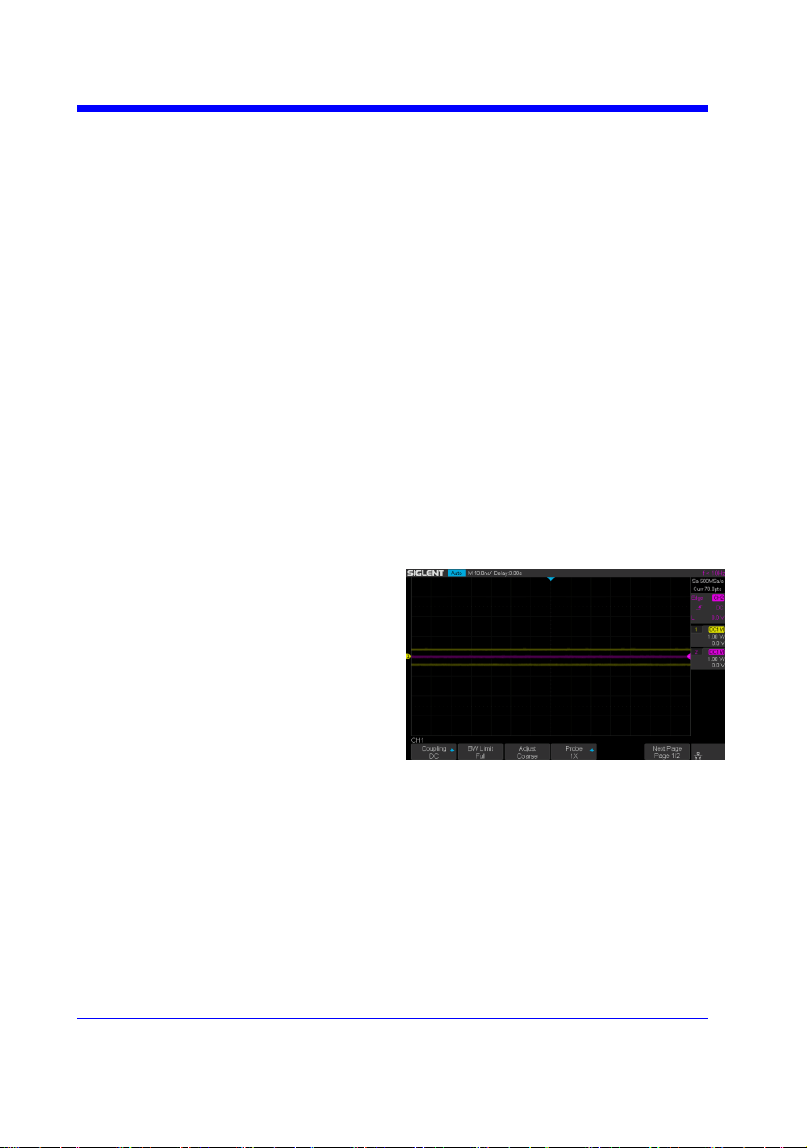
Digital Oscilloscope Series
139
SAVE
*SAV
Command
DESCRIPTION
The *SAV command stores the complete
front-panel setup of the instrument in
internal memory.
This instruction does not support storing to
external temporarily. See the command
STPN for external storage.
COMMAND SYNTAX
*SAV <setup_num>
<setup_num>:= 1 to 20.
Note:
If there is already a file in the specified
location, it will overwrite the original file.
EXAMPLE
When you want to save the current setup in
panel as shown below, the following
command saves it to setup No.3.
Command message:
*SAV 3
If you want to recall this setup, send the
following command.
Command message:
*RCL 3
RELATED COMMANDS
STPN
*RCL

Digital Oscilloscope Series
140
SAVE
PANEL_SETUP | PNSU
Command /Query
DESCRIPTION
The PANEL_SETUP command use the encoded
data get from ―PNSU?‖ to set the panel setup.
The PNSU? query return the panel setup in
binary format from scope.
COMMAND SYNTAX
PANEL_SETUP <binary data>
<binary data>:= A setup previously read by
PNSU?
QUERY SYNTAX
PANEL_SETUP?
RESPONSE FORMAT
PANEL_SETUP <binary data>
EXAMPLE
The following steps show how to use the query
and command to set the panel setup.
Step 1: Send the command to set the response
format.
Command message:
CHDR OFF
Step 2: Send the query to get the binary data of
setup.
Command message:
PNSU?
Response message:
<binary data>
Step 3: Change the panel setup, and then send
the command to restore setup get from step2.
Command message:
PNSU <binary data>
Step 4: You can also save the data in step 2 to a
text file and make it easier to recall later. The
following program is used as a reference.

Digital Oscilloscope Series
141

Digital Oscilloscope Series
142
SAVE
STORE_PANEL | STPN
Command
DESCRIPTION
The STORE_PANEL command stores the
complete front-panel setup of the instrument
into a file on the specified-DOS path
directory in a USB memory device.
See the command ―*SAV‖ for internal
storage.
COMMAND SYNTAX
STORE_PANEL
DISK,<device>,FILE,‗<filename>‘
<device>:= {UDSK}
<filename>:= A waveform file under a legal
DOS path.
Models
Description
SDS1000X-E
The filename string is
up to eight characters,
with the extension
―.xml‖.
Others
The filename string is
up to eight characters,
with the extension
―.set‖.
Note:
• See models on page 14.
• For SDS1000X-E series, the ‗/‘ character
to define the root directory is not supported.
• As shown below, during the execution of
the command, a progress bar will appear on
the interface. When the progress is finished,
there will be a prompt message.
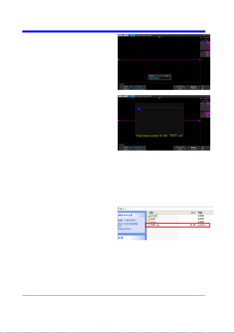
Digital Oscilloscope Series
143
EXAMPLE
• For SDS1000X-E series, the following
command saves the current setup to root
directory of the USB memory device in a
file called ―TEST.xml‖. Then you can see
the file on PC.
Command message:
STPN DISK,UDSK,FILE,’TEST.xml’
• For SDS1000X-E series, the following
command saves the current setup to
specified-directory of the USB memory
device in a file called ―TEST.xml‖. Then
you can see the file on PC.
Command message:
STPN DISK,UDSK,FILE,’/SAVE/TEST.xml’


Digital Oscilloscope Series
145
STATUS Commands
IEEE 488.2 defines data structures, commands, and common bit definitions for
status reporting. There are also instrument-defined structures and bits.
An overview of the oscilloscope's status reporting structure is shown in the
following commands.
INR?

Digital Oscilloscope Series
146
STATUS
INR?
Query
DESCRIPTION
The INR? query reads and clears the contents of
INternal state change Register (INR). The INR
register records the completion of various
internal operations and state transitions.
QUERY SYNTAX
INR?
RESPONSE FORMAT
INR <value>
<value>:= 0 to 65535.
Note :
• This query only returns 0 bit and 13 bit.
• See the table INternal State Register (INR)
Structure as shown below for details.
EXAMPLE
The following steps show the change of INR.
Step 1: When the trigger mode is single, and
there is no signal input, send the query.
Response message:
INR 0
Step 2: Now, input a signal to trigger. The
acquisition mode is Stop. Then, send the query.
Response message:
INR 1
Step 3: Now, change the trigger mode to Auto.
Then, send the query.
Response message:
INR 8193
Step 4: Now, change the trigger mode to Single.
The acquisition mode changes to be Stop. And
then, send the query.
Response message:
INR 8193

Digital Oscilloscope Series
147
Step 5: After sending the query in step 4, send
the query again.
Response message:
INR 0
Step 6: After step 2, not to input the signal,
change the trigger mode to single. And then,
send the query.
Response message:
INR 8192
INternal State Register (INR) Structure
Bit
Bit
value
Description
15
---
Not used (always 0)
14
---
Not used (always 0)
13
8192
Trigger is ready
12
4096
Pass/Fail test detected desired outcome
11
2048
Waveform processing has terminated in Trace D
10
1024
Waveform processing has terminated in Trace C
9
512
Waveform processing has terminated in Trace B
8
256
Waveform processing has terminated in Trace A
7
128
A memory card, floppy or hard disk exchange has been detected
6
64
Memory card, floppy or hard disk has become full in ―AutoStore
Fill‖ mode
5
---
Not use(always 0)
4
16
A segment of a sequence waveform has been acquired
3
8
A time-out has occurred in a data block transfer
2
4
A return to the local state is detected
1
2
A screen dump has terminated
0
1
A new signal has been acquired


Digital Oscilloscope Series
149
SYSTEM
*CAL?
Query
DESCRIPTION
The *CAL? query starts the user calibration
procedure and return a response.
The user calibration can quickly make the
oscilloscope achieve the best working state, in
order to obtain the most accurate measurement
value.
All function keys have been disabled during the
self calibration process.
Before starting the user calibration procedure,
you must disconnect anything from inputs.
QUERY SYNTAX
*CAL?
RESPONSE FORMAT
*CAL 0
• 0 — Calibration successful.
EXAMPLE
The following query starts a self-calibration.
Query message:
*CAL?
Response message:
*CAL 0

Digital Oscilloscope Series
150
SYSTEM
BUZZER | BUZZ
Command /Query
DESCRIPTION
The BUZZER command enables or disables the
buzzer.
The BUZZER? query returns the switch state of
the buzzer.
COMMAND SYNTAX
BUZZER <state>
<state>:= {ON,OFF}
QUERY SYNTAX
BUZZER?
RESPONSE FORMAT
BUZZER <state>
EXAMPLE
The following command enables the
oscilloscope buzzer.
Command message:
BUZZ ON

Digital Oscilloscope Series
151
SYSTEM
COMM_NET | CONET
Command /Query
DESCRIPTION
The COMM_NET command sets the IP address
of the oscilloscope‘s internal network interface.
When using this command, DHCP should be off.
The COMM_NET? query returns the IP address
of the oscilloscope‘s internal network interface.
COMMAND SYNTAX
COMM_NET
<ip_add0>,<ip_add1>,<ip_add2>,<ip_add3>
< ip_add0 >:= 1 to 223(except 127).
< ip_add1 >:= 0 to 255.
< ip_add2 >:= 0 to 255.
< ip_add3 >:= 0 to 255.
QUERY SYNTAX
COMM_NET?
RESPONSE FORMAT
COMM_NET
<ip_add0>,<ip_add1>,<ip_add2>,<ip_add3>
EXAMPLE
The following command sets the IP address to
10.11.0.230.
Command message:
CONET 10,11,0,230

Digital Oscilloscope Series
152
SYSTEM
SCREEN_SAVE | SCSV
Command/Query
DESCRIPTION
The SCREEN_SAVE command controls
the automatic screensaver, which
automatically shuts down the internal color
monitor after a preset time.
The SCREEN_SAVE? query returns
whether the automatic screensaver feature is
on.
Note:
When the screensaver is enabled, the
oscilloscope is still fully functional.
COMMAND SYNTAX
SCREEN_SAVE <time>
<time>:={OFF,1MIN,5MIN,10MIN,30MIN
,60MIN}
• OFF — Do not use screensaver.
• Others — When the oscilloscope enters
the idle state and holds for the specified
time, screensaver will be enabled.
QUERY SYNTAX
SCREEN_SAVE?
RESPONSE FORMAT
SCREEN_SAVE <time>
EXAMPLE
The following command sets the automatic
screensaver to 10 minutes.
Command message:
SCSV 10MIN


Digital Oscilloscope Series
154
TIMEBASE
TIME_DIV | TDIV
Command/Query
DESCRIPTION
The TIME_DIV command sets the
horizontal scale per division for the main
window.
The TIME_DIV? query returns the current
horizontal scale setting in seconds per
division for the main window.
COMMAND SYNTAX
TIME_DIV <value>
<value>:={1NS,2NS,5NS,10NS,20NS,50N
S,100NS,200NS,500NS,1US,2US,5US,10U
S,20US,50US,100US,200US,500US,1MS,2
MS,5MS,10MS,20MS,50MS,100MS,200M
S,500MS,1S,2S,5S,10S,20S,50S,100S}
• NS — for nanoseconds.
• US — for microseconds.
• MS — for milliseconds.
• S — for seconds.
Note:
The range of value varies from the models.
See the data sheet for details.
QUERY SYNTAX
TIME_DIV?
RESPONSE FORMAT
TIME_DIV <value>
<value>:= Numerical value in E-notation
with SI unit.
EXAMPLE
The following command sets the horizontal
scale to 500 μs.
Command message:
TDIV 500US
RELATED COMMANDS
TRDL
HMAG
HPOS

Digital Oscilloscope Series
155
TIMEBASE
TRIG_DELAY | TRDL
Command /Query
DESCRIPTION
The TRIG_DELAY command sets the time
interval between the trigger event and the
horizontal center point on the screen. The
maximum position value depends on the
time/division settings.
• Pre-trigger acquisition — Data acquired
before the trigger occurs. Negative trigger
delays must be given in seconds.
• Post-trigger acquisition — Data acquired
after the trigger has occurred.
The TRIG_DELAY? query returns the current
time from the trigger to the horizontal center
point in seconds.
COMMAND SYNTAX
TRIG_DELAY <delay>
<delay>:= time value with unit.
Note:
• The range of delay is related to the time
base. See the data sheet for details.
• If you set the delay to a value outside of the
legal range, the delay value is automatically
set to the nearest legal value.
QUERY SYNTAX
TRIG_DELAY?
RESPONSE FORMAT
TRIG_DELAY <value>
Model
Format of <skew>
SDS1000X-
E
Numerical value
in E-notation with
SI unit, such as
1.00E-04S.
others
Numerical value
with measurement
unit and physical


Digital Oscilloscope Series
157
TIMEBASE
HOR_MAGNIFY | HMAG
Command /Query
DESCRIPTION
The HOR_MAGNIFY command sets the
zoomed (delayed) window horizontal scale
(seconds/div). The main sweep scale determines
the range for this command. The maximum
value is the TDIV value.
The HOR_MAGNIFY? query returns the current
zoomed window scale setting.
COMMAND SYNTAX
Format 1:
HOR_MAGNIFY <value>
<value >:={1NS,2NS,5NS,10NS,20NS,50NS,10
0NS,200NS,500NS,1US,2US,5US,10US,20US,5
0US,100US,200US,500US,1MS,2MS,5MS,10M
S,20MS}
The range of value is related to the current time
base. It is from 1NS to the current time base.
Format 2:
HOR_MAGNIFY <factor>
<factor>:= 1 to 2,000,000.
The range of <factor> is related to the current
time base and the range of the time base.
Note:
The table on next page shows the available
format in each oscilloscope series.
QUERY SYNTAX
HOR_MAGNIFY?
RESPONSE FORMAT
HOR_MAGNIFY <value>
<value>:= Numerical value in E-notation with
SI unit.
HOR_MAGNIFY <factor>
EXAMPLE
For SDS1000X-E series, when the time base is
1ms/div, and Zoom function is on, the following

Digital Oscilloscope Series
158
command sets the zoomed (delayed) window
horizontal scale to 1US.
Command message:
HMAG 1US
RELATED COMMANDS
TDIV
Format in Each Oscilloscope Series
Model
Command Format
SDS1000CFL
Format 2
SDS1000A
Format 2
SDS1000CML+/CNL+/DL+/E+/F+
Format 2
SDS2000X
Format 2
SDS1000X
Format 2
SDS1000X-E
Format 1

Digital Oscilloscope Series
159
TIMEBASE
HOR_POSITION | HPOS
Command /Query
DESCRIPTION
The HOR_POSITION command sets the
horizontal position in the zoomed (delayed) view
of the main sweep. The main sweep range and
the main sweep horizontal position determine the
range for this command. The value for this
command must keep the zoomed view window
within the main sweep range.
The HOR_POSITION? query the current
horizontal window position setting in the
zoomed view.
COMMAND SYNTAX
Format 1:
HOR_POSITION <position>
<position>:= time value with unit.
Note:
• You need add the time unit(s/ms/us/ns) to the
position. If there is no unit added, it defaults to
be S.
• The range of position is related to the main
sweep range and the main sweep horizontal
position. The range after magnifying which
beyond the screen could display, and it will be
adjusted to the proper value.
Format 2:
HOR_POSITION <factor_div>
< factor_div>:= the factor of zoomed time base.
Note:
The table on next page shows the available
format in each oscilloscope series.
QUERY SYNTAX
HOR_POSITION?
RESPONSE FORMAT
HOR_POSITION <position>
<position>:= Numerical value in E-notation with
SI unit.

Digital Oscilloscope Series
160
HOR_POSITION <factor_div>
EXAMPLE
For SDS1000X-E series, when the time base is
10 us/div, the horizontal position is 0, Zoom
function is on, and the zoomed scale is 5 us. The
range of zoom position is from -35 us to 35 us.
The following command sets the zoom position
to 100 ns.
Command message:
HPOS 100ns
RELATED COMMANDS
HMAG
TDIV
TRDL
Format in Each Oscilloscope Series
Model
Command Format
SDS1000CFL
Format 2
SDS1000A
Format 2
SDS1000CML+/CNL+/DL+/E+/F+
Format 2
SDS2000X
Format 2
SDS1000X
Format 2
SDS1000X-E
Format 1


Digital Oscilloscope Series
162
TRIGGER
SET50
Command
DESCRIPTION
The SET50 command automatically sets the
trigger levels to center of the trigger source
waveform.
When High and Low (dual) trigger levels
are used (as Runt triggers, for example), this
command has no effect.
COMMAND SYNTAX
SET50
EXAMPLE
When the trigger type is edge and the
trigger source is Channel 1, the following
command sets the trigger level to the center
of Channel 1.
Command message:
SET50
RELATED COMMANDS
TRLV

Digital Oscilloscope Series
163
TRIGGER
TRIG_COUPLING | TRCP
Command /Query
DESCRIPTION
The TRIG_COUPLING command sets the
input coupling for the selected trigger sources.
The TRIG_COUPLING? query returns the
trigger coupling of the selected source.
COMMAND SYNTAX
<trig_source>:TRIG_COUPLING
<trig_coupling>
<trig_source>:={C1,C2,C3,C4,EX,EX5}
<trig_coupling>:={AC,DC,HFREJ,LFREJ}
• AC — AC coupling block DC component
in the trigger path, removing dc offset voltage
from the trigger waveform. Use AC coupling
to get a stable edge trigger when your
waveform has a large dc offset.
• DC — DC coupling allows dc and ac
signals into the trigger path.
• HFREJ — HFREJ coupling places a low-
pass filter in the trigger path.
• LFREJ — LFREJ coupling places a high-
pass filter in the trigger path.
QUERY SYNTAX
<trig_source>:TRIG_COUPLING?
RESPONSE FORMAT
<trig_source>:TRIG_COUPLING
<trig_coupling>
EXAMPLE
The following command sets the coupling
mode of the trigger source Channel 2 to AC.
Command message:
C2:TRCP AC
RELATED COMMANDS
TRSE

Digital Oscilloscope Series
164
TRIGGER
TRIG_LEVEL | TRLV
Command /Query
DESCRIPTION
The TRIG_LEVEL command sets the trigger
level voltage for the active trigger source.
When there are two trigger levels to set, this
command is used to set the higher trigger level
voltage for the specified source. TRLV2 is
used to set the lower trigger level voltage.
The TRIG_LEVEL? query returns the trigger
level of the current trigger source.
COMMAND SYNTAX
<trig_source>:TRIG_LEVEL <trig_level>
<trig_source>:={C1,C2,C3,C4,EX,EX5}
<trig_level>:= -4.5*DIV to 4.5*DIV for
internal triggers.
<trig_level>:= -3*DIV to 3*DIV for external
triggers.
Note:
• You need to add the volt unit(V/mV) to the
trig_level. If there is no unit added, it defaults
to volts (V).
• An out-of-range value will be adjusted to
the closest legal value.
QUERY SYNTAX
<trig_source>:TRIG_LEVEL?
RESPONSE FORMAT
<trig_source>:TRIG_LEVEL <trig_level>
<trig_level>:= Numerical value in E-notation
with SI unit.
EXAMPLE
When the vertical scale of Channel 3 is 200
mV, and the trigger source is Channel 3, the
following command sets the trigger level of
Channel 3 to 52.00 mV.
Command message:
C3:TRLV52MV


Digital Oscilloscope Series
166
TRIGGER
TRIG_LEVEL2 | TRLV2
Command /Query
DESCRIPTION
The TRIG_LEVEL2 command sets the lower
trigger level voltage for the specified source.
Higher and lower trigger levels are used with
runt /slope triggers.
The TRIG_LEVEL2? query returns the lower
trigger level voltage for the specified source.
COMMAND SYNTAX
<trig_source>:TRIG_LEVEL2 <trig_level>
<trig_source>:= {C1,C2,C3,C4}
<trig_level>:= -4.5*DIV to 4.5*DIV.
Note:
• You need add the volt unit(V/mV) to the
trig_level. If there is no unit added, it defaults
to volts (V).
• An out-of-range value will be adjusted to
the closest legal value.
QUERY SYNTAX
<trig_source>:TRIG_LEVEL2?
RESPONSE FORMAT
<trig_source>:TRIG_LEVEL2 <trig_level>
<trig_level>:= Numerical value in E-notation
with SI unit.
EXAMPLE
When the trigger type is slope, the following
steps set the high trigger level of Channel 2 to
3.5 V, and the low trigger level of Channel 2
to 800 mV.
Step 1: Send the command to set high trigger
level.
Command message:
C2:TRLV 3.5V
Step 2: Send the command to set low trigger
level.
Command message:


Digital Oscilloscope Series
168
TRIGGER
TRIG_MODE | TRMD
Command /Query
DESCRIPTION
The TRIG_MODE command selects the
trigger sweep mode.
The TRIG_MODE? query returns the current
trigger sweep mode.
COMMAND SYNTAX
TRIG_MODE <mode>
<mode>:= {AUTO,NORM,SINGLE,STOP}
• AUTO — When AUTO sweep mode is
selected, the oscilloscope begins to search for
the trigger signal that meets the conditions.
If the trigger signal is satisfied, the running
state on the top left corner of the user interface
shows Trig'd, and the interface shows stable
waveform.
Otherwise, the running state always shows
Auto, and the interface shows unstable
waveform.
• NORM — When NORMAL sweep mode is
selected, the oscilloscope enters the wait
trigger state and begins to search for trigger
signals that meet the conditions.
If the trigger signal is satisfied, the running
state shows Trig'd, and the interface shows
stable waveform.
Otherwise, the running state shows Ready, and
the interface displays the last triggered
waveform (previous trigger) or does not
display the waveform (no previous trigger).
• SINGLE — When SINGLE sweep mode is
selected, the backlight of SINGLE key lights
up, the oscilloscope enters the waiting trigger
state and begins to search for the trigger signal
that meets the conditions.
If the trigger signal is satisfied, the running
state shows Trig'd, and the interface shows
stable waveform. Then, the oscilloscope stops
scanning, the RUN/STOP key is red light, and
the running status shows Stop.

Digital Oscilloscope Series
169
Otherwise, the running state shows Ready, and
the interface does not display the waveform.
• STOP — STOP is a part of the option of
this command, but not a trigger mode of the
oscilloscope.
QUERY SYNTAX
TRIG_MODE?
RESPONSE FORMAT
TRIG_MODE <mode>
EXAMPLE
The following command sets the trigger mode
to Normal.
Command message:
TRMD NORM
RELATED COMMANDS
ARM
STOP

Digital Oscilloscope Series
170
TRIGGER
TRIG_PATTERN | TRPA
Command /Query
DESCRIPTION
The TRIG_PATTERN command specifies the
channel values to be used in the pattern trigger
and sets the condition of the pattern trigger.
The TRIG_PATTERN? query returns channel
values and the condition of the pattern trigger.
COMMAND SYNTAX
TRIG_PATTERN
<source>,<status>[,<source>,<status>[,<sourc
e>,<status>[,<source>,<status>]]],STATE,<co
ndition>
< source >:={C1,C2,C3,C4}
<status>:={X,L,H}
< condition >:={AND,OR,NAND,OR}
• X — Ignore this channel. When all channels
are set to X, the oscilloscope will not trigger.
• L — Low level.(lower than the threshold
level of the channel)
• H — High level.(higher than the threshold
level of the channel)
Note:
The status of source can only be set when the
source is on.
QUERY SYNTAX
TRIG_PATTERN?
RESPONSE FORMAT
TRIG_PATTERN
<source>,<status>,<source>,<status>,<source
>,<status>,<source>,<status>,STATE,<condit
ion>
EXAMPLE
When the trigger type is Pattern, and Channel
2 & Channel 3 are on, the following command
sets the Channel 2 and Channel 3 to low and
the condition to AND.
Command message:
TRPA C2,L,C3,L,STATE,AND

Digital Oscilloscope Series
171
TRIGGER
TRIG_SELECT | TRSE
Command /Query
DESCRIPTION
The TRIG_SELECT command selects the
condition that will trigger the acquisition of
waveforms.
Depending on the trigger type, additional
parameters must be specified. These additional
parameters are grouped in pairs. The first in
the pair names the variable to be modified,
while the second gives the new value to be
assigned. Pairs may be given in any order and
restricted to those variables to be changed.
The TRIG_SELECT? query returns the
current trigger condition.
Parameter description
SLE
W
Slope
IL
Interval
larger
GLI
T
Glitch/
Pulse
IS
Interval
smaller
INT
V
Interva
l
I2
Interval
in range
DRO
P
Dropo
ut
I1
Interval
out of
range
SR
Source
P
L
Pulse
larger
TI
Time
PS
Pulse
smaller
HT
Hold
type/
Limit
range
P2
Pulse in
range
HV
Hold
value/
Limit
value
P1
Pulse out
of range
COMMAND SYNTAX
(FOR ALL BUT TV)
TRIG_SELECT
<trig_type>,SR,<source>,HT,<hold_type>,H
V,<hold_value1>[,HV2,<hold_value2>]

Digital Oscilloscope Series
172
<trig_type>:={EDGE,SLEW,GLIT,INTV,RU
NT,DROP}
<source>:={C1,C2,C3,C4,LINE,EX,EX5}
Note:
LINE/EX/EX5 can only be selected when the
trigger type is Edge.
<hold_type>:={TI,OFF} for EDGE trigger.
<hold_type>:={TI} for DROP trigger.
<hold_type>:={PS,PL,P2,P1}for GLIT/RUNT
trigger.
<hold_type>:={IS,IL,I2,I1} for SLEW/INTV
trigger.
<hold_value1>:= a time value with unit.
<hold_value2>:= a time value with unit.
Note:
• If there is no unit(S/mS/uS/nS) added, it
defaults to be S.
• The range of hold_values varies from
trigger types. [80nS, 1.5S] for Edge trigger,
and [2nS, 4.2S] for others.
QUERY SYNTAX
TRIG_SELECT?
RESPONSE FORMAT
TRIG_SELECT
<trig_type>,SR,<source>,HT,<hold_type>,H
V,<hold_value1>[,HV2,<hold_value2>]
EXAMPLE
• When you want to set trigger type to Edge,
trigger source to Channel 1, hold type to
TIME, and the time value to 1.43uS, the
following comes true.
Command message:
TRSE EDGE,SR,C1,HT,TI,HV,1.43uS
• When you want to set trigger type to Pulse,
trigger source to Channel 2, limit range to
[5nS, 1uS] , the following comes true.
Command message:

Digital Oscilloscope Series
173
TRSE GLIT,SR,C2,HT,P2,HV,5nS,HV2,1uS
• When you want to set trigger type to
Dropout, trigger source to Channel 4, overtime
value to 2.8 mS , the following comes true.
Command message:
TRSE DROP,SR,C4,HT,TI,HV,2.8mS
TV COMMAND SYNTAX
TRIG_SELECT
<trig_type>,SR,<source>,STAN,<standard>,S
YNC,<sync_type>[,LINE,<line>[,FLD,<field
>]]
Parameter description
STAN
Standard
FLD
field
CUST
Custom
<trig_type>:= {TV}
<source>:={C1,C2,C3,C4}
<standard>:={NTSC,PAL,720P/50,720P/60,1
080P/50,1080P/60,1080I/50,1080I/60, CUST}
<line>:=allows triggering on a specific line of
video. The line number limits vary with the
standard and mode, as shown in the following
table.
TV Trigger Line Number Limits
stand
ard
Mode
Line
Field
1
Field
2
NTSC
1~26
3
1 to 262
PAL
1 to
313
1 to 312
720P/
50
1 to
750
720P/
60
1 to
750
1080P
/50
1-
1125
1080P
/60
1-
1125

Digital Oscilloscope Series
174
1080I/
50
1 to
563
1 to 562
1080I/
60
1 to
563
1 to 562
CUST
1 to number of Lines
<field>:= [1,2]
for NTSC/PAL/1080I/50/1080I/60
<field>:=1 to <field_count>for CUST.
<field_count>:=1 to 8 depending on the
interlace.
Note:
Field can only be selected when the standard
is NTSC/PAL/1080I/50/1080I/60/CUST.
TV QUERY SYNTAX
TRIG_SELECT?
TV RESPONSE FORMAT
TRIG_SELECT
<trig_type>,SR,<source>,STAN,<standard>,S
YNC,<sync_type>[,LINE,<line>[,FLD,<field
>]]
TV EXAMPLE
• When you want to set trigger type to Video,
trigger source to Channel 1, standard to
NTSC, and SYNC to ANY, the following
comes true.
Command message:
TRSE TV,SR,C1,STAN,NTSC,SYNC,ANY
• When you want to set trigger type to Video,
trigger source to Channel 1, standard to PAL,
Line to 300, and Field to 2, the following
comes true.
Command message:
TRSE
TV,SR,C1,STAN,PAL,SYNC,SELECT,LINE,30
0,FLD,2
• When you want to set trigger type to Video,
trigger source to Channel 2, standard to
1080P/50, and Line to 200, the following

Digital Oscilloscope Series
175
comes true.
Command message:
TRSE
TV,SR,C2,STAN,1080P/50,SYNC,SELECT,LI
NE,200

Digital Oscilloscope Series
176
TRIGGER
TRIG_SLOPE | TRSL
Command /Query
DESCRIPTION
The TRIG_SLOPE command sets the trigger
slope of the specified trigger source.
The TRIG_SLOPE? query returns the trigger
slope of the selected source.
COMMAND SYNTAX
<trig_source>:TRIG_SLOPE <trig_slope>
<trig_source>:={C1,C2,C3,C4,EX,EX5}
<trig_slope>:={NEG,POS,WINDOW} for
edge trigger.
<trig_slope>:={NEG,POS} for other trigger.
• NEG — falling edg.
• POS — rising edge.
• WINDOW — altering edge.
QUERY SYNTAX
<trig_source>:TRIG_SLOPE?
RESPONSE FORMAT
<trig_source>:TRIG_SLOPE <trig_slope>
EXAMPLE
The following command sets the trigger slope
of Channel 2 to negative.
Command message:
C2:TRSL NEG
RELATED COMMANDS
TRSE

Digital Oscilloscope Series
177
TRIGGER
TRIG_WINDOW | TRWI
Command /Query
DESCRIPTION
The TRIG_WINDOW command sets the
relative height of the two trigger line of the
trigger window type.
Note:
This command is only valid when the window
type is relative.
The TRIG_WINDOW? query returns relative
height of the two trigger line of the trigger
window type.
COMMAND SYNTAX
TRIG_WINDOW <value>
<value>: 0 to 9*DIV when the center level is
0.
Note:
• You need add the volt unit(V/mV) to the
value. If there is no unit added, it defaults to
be V.
• The range of value is related to the center
value of the level.
QUERY SYNTAX
TRIG_WINDOW?
RESPONSE FORMAT
TRIG_WINDOW <value>
<value>:= Numerical value in E-notation with
SI unit.
EXAMPLE
When the window type is relative, and the
center level is 1 V, the following command
sets the relative height of the two trigger line
to 2 V.
Command message:
TRWI 2V
RELATED COMMANDS
TRLV
TRLV2

Digital Oscilloscope Series
178
WAVEFORM Commands
The WAVEFORM subsystem is used to transfer data to a controller from the
oscilloscope waveform memory.
The waveform record is actually contained in two portions: the preamble and
waveform data. The waveform record must be read from the oscilloscope by the
controller using two separate commands. The waveform data is the actual data
acquired for each point in the specified source. The preamble contains the
information for interpreting the waveform data.
WF?
WFSU

Digital Oscilloscope Series
179
WAVEFORM
WAVEFORM? | WF?
Query
DESCRIPTION
The WAVEFORM? query transfers a
waveform from the oscilloscope to the
controller.
Note:
The format of the waveform data depends
on the current settings specified by the last
WFSU command.
QUERY SYNTAX
<trace>:WAVEFORM? <section>
<trace>:={C1,C2,C3,C4,MATH,D0,D1,D2,
D3,D4,D5,D6,D7,D8,D9,D10,D11,D12,D1
3,D14,D15}
• C[X] — Analog channel.
• D[X] — Digital channel. Only valid for
SDS1000X-E series.
• MATH — Valid except for the FFT
waveform and only valid for SDS1000X-E
series.
<section>:={DAT2}
• DAT2 — Return the main data include
the head, the wave data and the ending flag.
The length of data is current memory depth.
RESPONSE FORMAT
<trace>:WAVEFORM <data block>
RELATED COMMANDS
WFSU
EXAMPLE
For SDS1000X-E series, the following steps
show how to use the command to
reconstitute the display of waveform.
For analog channel waveform:
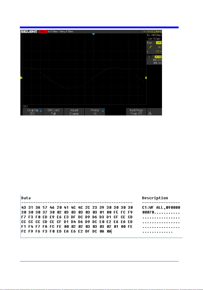
Digital Oscilloscope Series
180
Step 1: Send the query to get the data of waveform.
Query message:
C1:WF? DAT2
Response message:
The head of message: C1:WF ALL. These are followed by the string
#9000000070, the beginning of a binary block in which nine ASCII
integers are used to give the length of the block (70 bytes). After the
length of block, is beginning of the wave data. ―0A 0A‖ means the end
of data.
Step 2: Calculate the voltage value corresponding to the data point.
Using the formula: voltage value (V) = code value *(vdiv /25) - voffset.

Digital Oscilloscope Series
181
code value: The decimal of wave data.
Note: If the decimal is greater than ―127‖, it should minus 255.Then the
value is code value. Such as the wave data is ―FC‖ convert to decimal is
―252‖. So the code value is 252-255 = -3.
vdiv: The Volts/div value.
voffset: The voltage position value.
The picture above as an example:
Send command C1:VDIV?
Return C1:VDIV 5.00E-01V.
Get the current Volts/div values: vdiv = 0.5V.
Send command C1:OFST?
Return C1:OFST -5.00E-01V.
Get the current voltage position values: voffset = -0.5V.
According to the wave data, we can know the first point of waveform is
the 22th data ―02‖, convert to decimal is ―2‖ (Hexadecimal converted to
decimal).
The first point of wave data voltage value = 2*(0.5/25)-(-0.5) = 0.54V.
Step 3: Calculate the time value of the data point.
Using the formula: time value(S) = -(timebase*grid/2).
timebase: The timebase value.
grid: The grid numbers in horizontal direction.
The picture above as an example:
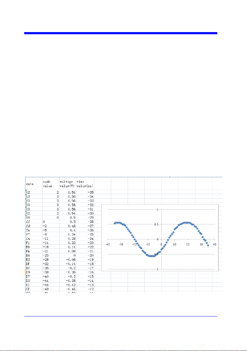
Digital Oscilloscope Series
182
Send command TDIV?
Return TDIV 5.00E-09S.
Get the current timebase: timebase = 5.00E-09S.
The time value of the first data point: time value = - (5.00E-09*14/2) = -
35.00E-09(s) = -35(ns).
Send command SARA?
Return SARA 1.00E+09Sa/s.
Get the current sampling rate: sampling rate= 1.00GSa/s.
The time interval: time inter = 1/ sampling rate = 1ns.
So the time value of the second data point: value = -35ns+1ns = -34ns.
The following are two ways of waveform reconstruction:
Use Excel to reconstruct the waveform:
Use python to reconstruct the waveform: (See the code in Read Waveform
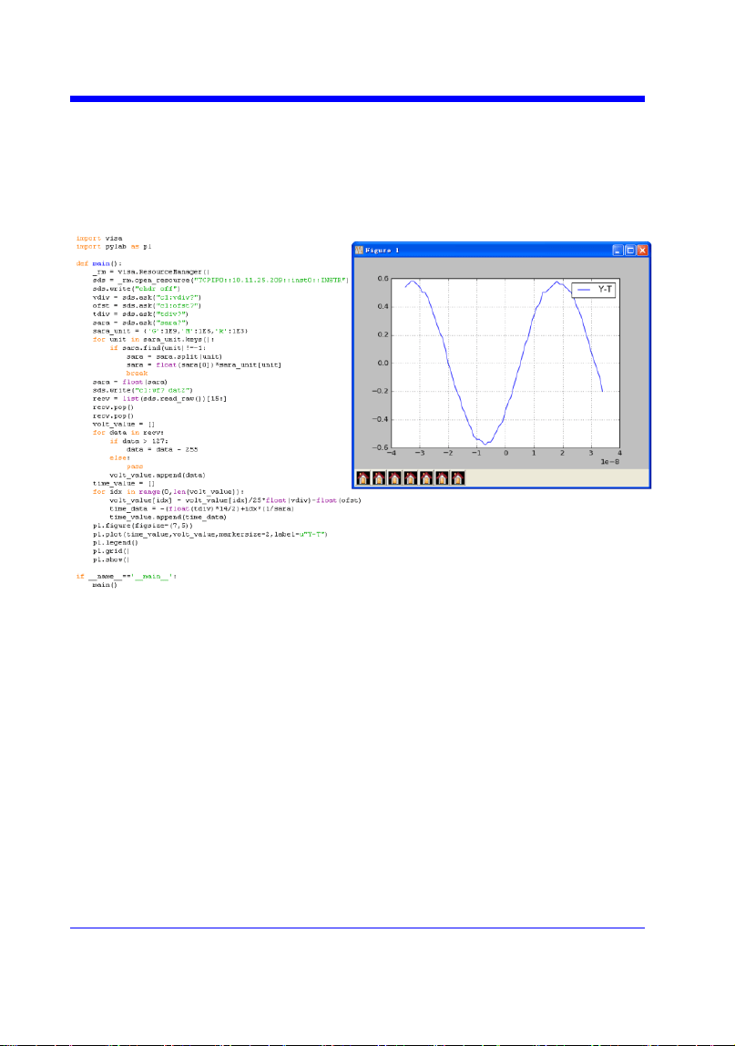
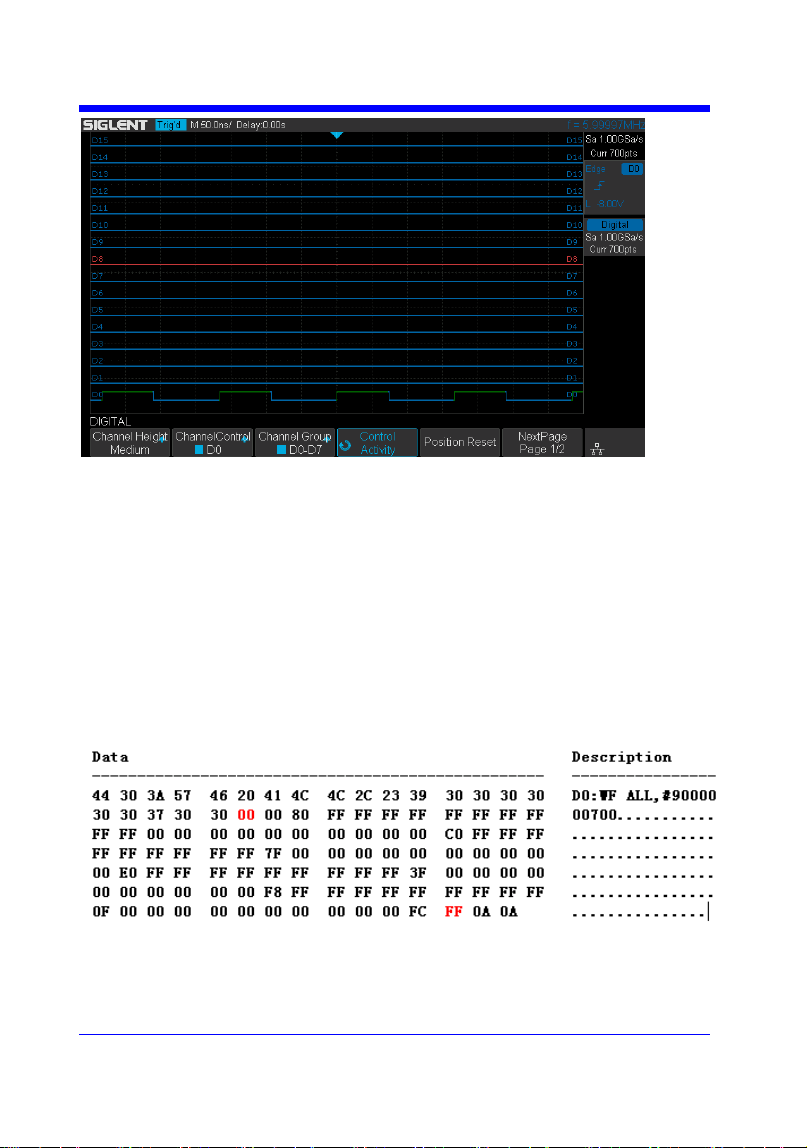
Digital Oscilloscope Series
184
Step 1: Send the query to get the data of waveform.
Query message:
D0:WF? DAT2
Response message:
The head of message: D0:WF ALL. These are followed by the string
#9000000700, the beginning of a binary block in which nine ASCII
integers are used to give the length of the data (700 points). For digital,
one bit represents a data point, so there are 88 bytes. After the length of
block, is beginning of the wave data. ―0A 0A‖ means the end of data.
Step 2: Covert to the high (1) and low (0) corresponding to the data point.
According to the wave data, we can know the first eight points of

Digital Oscilloscope Series
185
waveform is the 22th byte ―00‖, convert to binary is ―00000000‖
(Hexadecimal converted to binary (LSB)).
Step 3: Calculate the time value of the data point.
Using the formula: time value(S) = - (timebase*grid/2).
timebase: The timebase value.
grid: The grid numbers in horizontal direction.
The picture above as an example:
Send command TDIV?
Return TDIV 5.00E-08S.
Get the current timebase: timebase = 5.00E-08S.
The time value of the first data point: time value = - (5.00E-08*14/2) = -
3.50E-07(s) = -350(ns).
Send command DI:SARA?
Return DI:SARA 1.00E+09Sa/s.
Get the current sampling rate: sampling rate= 1GSa/s.
The time interval: time inter = 1/ sampling rate = 1ns.
So the time value of the second data point: value = -350ns+1ns = -349ns.
Use python to reconstruct the waveform: (See the code in Read Waveform
Data of Digital Example)
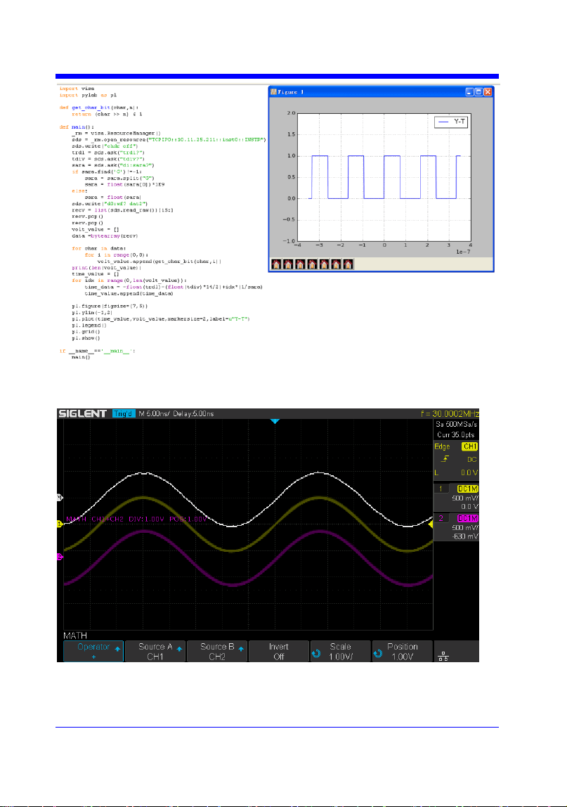
Digital Oscilloscope Series
186
For math (except for FFT) waveform:
Step 1: Send the query to get the data of waveform.
Query message:
Digital Oscilloscope Series
187
MATH:WF? DAT2
Response message:
The head of message: MATH:WF ALL. These are followed by the string
#9000000700, the beginning of a binary block in which nine ASCII
integers are used to give the length of the block (700 bytes). The point
number is 700 with interpolation. After the length of block, is beginning
of the wave data. ―0A 0A‖ means the end of data.
Step 2: Calculate the voltage value corresponding to the data point.
Using the formula: voltage value (V) = code value *(vdiv /25).
code value: The decimal of wave data. Different from the code of analog
channel waveform, it contains the offset.
Note: If the decimal is greater than ―127‖, it should minus 255.Then the
value is code value. Such as the wave data is ―FC‖ convert to decimal is
―252‖. So the code value is 252-255 = -3.
vdiv: The Volts/div value of math.
The picture above as an example:
Send command MTVD?
Return MTVD 1.00E+00V.
Get the current Volts/div values: vdiv = 1V.
According to the wave data, we can know the first point of waveform is

Digital Oscilloscope Series
188
the 24th data ―FF‖, convert to decimal is ―255‖ (Hexadecimal converted
to decimal). Then minus 255, the code value is 0.
The first point of wave data voltage value = 0*(1/25) = 0V.
Step 3: Calculate the time value of the data point.
Using the formula: time value(S) = - (timebase*grid/2).
timebase: The timebase value.
grid: The grid numbers in horizontal direction.
The picture above as an example:
Send command TDIV?
Return TDIV 5.00E-09S.
Get the current timebase: timebase = 5.00E-09S.
The time value of the first data point: time value = - (5.00E-09*14/2) = -
35.00E-09(s) = -35(ns).
Send command SARA?
Return SARA 5.00E+08Sa/s.
Get the current sampling rate: sampling rate= 500MSa/s.
Send command SANU? C1
Return SANU 3.50E+01pts.
Get the number of sampling points: points number = 35pts.
The interpolation multiplier: interpolation multiplier = length of the
block / points number = 700/35 = 20
The time interval: time inter = 1/ sampling rate/ interpolation multiplier
= 0.1ns.
Digital Oscilloscope Series
189
So the time value of the second data point: value = -35ns+0.1ns = -
34.9ns.
Use python to reconstruct the waveform:

Digital Oscilloscope Series
190
WAVEFORM
WAVEFORM_SETUP |WFSU
Command/Query
DESCRIPTION
The WAVEFORM_SETUP command
specifies the amount of data in a waveform
to be transmitted to the controller.
The WAVEFORM_SETUP? query returns
the transfer parameters currently in use.
COMMAND SYNTAX
WAVEFORM_SETUP
SP,<sparsing>,NP,<number>,FP,<point>
• SP — Sparse point. It defines the interval
between data points.
For example:
SP = 0 sends all data points.
SP = 4 sends every 4 data points.
• NP — The number of points. It indicates
how many points should be transmitted. For
example:
NP = 0 sends all data points.
NP = 50 sends a maximum of 50 data
points.
• FP — First point. It specifies the address
of the first data point to be sent. For
waveforms acquired in sequence mode, this
refers to the relative address in the given
segment.
For example:
FP = 0 corresponds to the first data point.
FP = 1 corresponds to the second data point.
Note:
• You can set the sparse point or number of
points or the first point using key-value
pairs alone. See the example for details.
• After power on, SP is set to 0,NP is set to
0,and FP is set to 0.

Digital Oscilloscope Series
191
QUERY SYNTAX
WAVEFORM_SETUP?
RESPONSE FORMAT
WAVEFORM_SETUP
SP,<sparsing>,NP,<number>,FP,<point>
EXAMPLE
The following command specifies that
every 3 data points (SP=3) starting at the
200
th
point should be transferred.
Command message:
WFSU SP,3,FP,200
RELATED COMMANDS
WF?

Digital Oscilloscope Series
192
WGEN Commands
When the built-in waveform generator is licensed (Option AWG), you can use it
to output sine, square, ramp, pulse, DC, noise, exponential rise, exponential fall,
cardiac, Gaussian pulse and arbitrary waveforms. The WGEN commands are
used to select the waveform function and parameters.
ARWV
PROD?
STL?
WGEN
WVPR?
Note:
These commands are only valid for the model which has installed AWG option.
Availability of WGEN Commands in Each Oscilloscope Series
Model
Valid?
SDS1000CFL
no
SDS1000A
no
SDS1000CML+/CNL+/DL+/E+/F+
no
SDS2000X
yes
SDS1000X
yes
SDS1000X-E
no

Digital Oscilloscope Series
193
WGEN
ARBWAVE | ARWV
Command
DESCRIPTION
The ARBWAVE command sets the basic
waveform type.
COMMAND SYNTAX
ARBWAVE INDEX,<index>
<index>:= {0,1,2,3,4,5,6,7,8,9}.
EXAMPLE
For SDS2000X series, when the AWG
option is installed, the following command
set the index of waveform type to 3.
Command message:
ARWV INDEX,3
Note:
See the table Availability of WGEN Commands in Each Oscilloscope Series for details.

Digital Oscilloscope Series
194
WGEN
PRODUCT? | PROD?
Query
DESCRIPTION
The PRODUCT? query returns the product
model or the upper limit of frequency of the
output signal.
QUERY SYNTAX
PRODUCT? <parameter>
<parameter>:={MODEL,BAND}
• MODEL — return the product model.
• BAND — return the upper limit of
frequency of the output signal.
RESPONSE FORMAT
PRODUCT <parameter>,<value>
EXAMPLE
For SDS2000X series, when the AWG
option is installed, the following query
returns the upper limit of frequency of the
output signal.
Query message:
PROD? BAND
Response message:
PROD BAND,25MHz
Note:
See the table Availability of WGEN Commands in Each Oscilloscope Series for details.

Digital Oscilloscope Series
195
WGEN
STORELIST? | STL?
Query
DESCRIPTION
The STORELIST? query returns the stored
arbitrary waveforms list with indexes and
names. If the store unit is empty, the
command will return ―EMPTY‖ string.
QUERY SYNTAX
STORELIST? <type>
<type>:={DEBUG,RELEASE}
• DEBUG — return built-in waveforms.
(include sine, noise, cardiac, gaus_pulse,
exp_rise, exp_fall, and four waveforms
defined by user)
• RELEASE — return four waveforms
defined by user.
RESPONSE FORMAT
STORELIST <list>
EXAMPLE
For SDS2000X series, when the AWG
option is installed, the following query
returns the waveform storage list.
Query message:
STL? DEBUG
Response message:
STL
M0,SINE,M1,NOISE,M2,CARDIAC,M3,GA
US_PULSE,M4,EXP_RISE,M5,EXP_FALL,
M6,EMPTY,M7,EMPTY,M8,EMPTY,M9,E
MPTY
Note:
See the table Availability of WGEN Commands in Each Oscilloscope Series for details.

Digital Oscilloscope Series
196
WGEN
WAVEGENERATOR | WGEN
Command/Query
DESCRIPTION
The WAVEGENERATOR command sets
parameters of basic waveform.
The WAVEGENERATOR? query returns
the waveform parameters.
COMMAND SYNTAX
WAVEGENERATOR
<parameter>,<value>
<parameter>:= {a parameter from the table
below}.
<value>:={value of the corresponding
parameter}.
Parameters
Value
Description
OUTP
<state>
:={ON,OFF}.
WVTP
<type>
:={SINE,SQUARE,RAMP,PULSE,DC,NOISE,CA
RDIAC,GAUS_PULSE,EXP_RISE,EXP_FALL,A
RB1,ARB2,ARB3,ARB4}. If the command doesn‘t
set basic waveform type, WVPT will be set to the
current waveform.
FREQ
<frequency>
:= 0.000001 Hz to 25000000 Hz. Not valid when
WVTP is NOISE or DC.
AMPL
<amplitude>
:= 0.004V to 6 V. Not valid when WVTP is NOISE
or DC.
OFST
<offset>
:= -(6 - AMP)/2 to (6 - AMP)/2(V). Not valid when
WVTP is NOISE.
DCOFST
<dc_offset>
:= -3V to 3 V. Only valid when WVTP is DC.
DUTY
<duty>
:= 20% to 80%. Only valid when WVTP is
SQUARE.
SYMM
<sym>
:= 0 to 100%. Only valid when WVTP is RAMP.
WIDTH
<width>
:= 0.000000048s to 0.001s. Only valid when WVTP
is PULSE.
STDEV
<std>
:= 0.0003V to 0.45V. Only valid when WVTP is
NOISE.
MEAN
<mean>
:= -(0.45-STD)*(20/3)-(0.45-STD)*(20/3) (V). Only
valid when WVTP is NOISE.

Digital Oscilloscope Series
197
LOAD
<load>
:={ HZ, 50}.
QUERY SYNTAX
WAVEGENERATOR? <parameter>
<parameter>:={OUTP,WVTP,FREQ,AMP
L,OFST,DCOFST,DUTY,SYMM,WIDTH,
STDEV,MEAN,LOAD,ALL}
RESPONSE FORMAT
WAVEGENERATOR
<parameter>,<value>
EXAMPLE
• For SDS2000X series, when the AWG
option is installed, the following command
set the type to square, amplitude to 2.5 V,
frequency to 10 kHz and duty to 45%.
Command message:
WGEN
TYPE,SQUARE,FREQ,10000Hz,AMPL,2.5
V,DUTY,45%
• For SDS2000X series, when the AWG
option is installed, the following command
set the type to noise, stdev to 0.2 V, mean to
1 V.
Command message:
WGEN
TYPE,NOISE,STDEV,0.2V,MEAN,1V
• For SDS2000X series, when the AWG
option is installed, the following command
set the output to off.
Command message:
WGEN OUPT,OFF
Note:
See the table Availability of WGEN Commands in Each Oscilloscope Series for details.

Digital Oscilloscope Series
198
WGEN
WAVE_PARA? | WVPR?
Query
DESCRIPTION
The WAVE_PARA? query returns the
location, name, frequency, amplitude, and
offset of four arbitrary waveforms.
QUERY SYNTAX
WAVE_PARA? <index>
RESPONSE FORMAT
WAVE_PARA
POS,<index>,WVNM,<name>,FREQ,<freq
>,AMPL,<ampl>,OFST,<ofst>
EXAMPLE
For SDS2000X series, when the AWG
option is installed, the following query
returns the parameters of M0.
Query message:
WVPR? M0
Response message:
WVPR
POS,M0,WVNM,SINE,FREQ,1.000000e+0
3,AMPL,6.000000e+00,OFST,0.000000e+0
0
RELATED COMMANDS
STL?
Note:
See the table Availability of WGEN Commands in Each Oscilloscope Series for details.

Digital Oscilloscope Series
199
Obsolete Commands for Old Models
Obsolete commands are older forms of commands that are provided to reduce
customer rework for existing systems and programs.
Generally, these commands are mapped onto some of the commands, but may
not strictly have the same behavior as the new command.
None of the obsolete commands are guaranteed to remain functional in future
products. New systems and programs should use the new commands.
Obsolete command
Current Command
Equivalent
Behavior Differences
ACAL
none
AUTTS
none
COUN
none
CRAU
none
CSVS
none
DATE
none
FFTZ
FFTT?
Modify the instruction name
and usage.
FILT
none
FILTS
none
PDET
ACQW
The instructions are merged
into one.
PERS
PESU
The instructions are merged
into one.
PFCT
PFSC|PFBF|PFOP|P
FFS
Split one command into
multiple commands.
REC
none
REFS
REFSR|REFLA|REF
DS|REFSA
Split one command into
multiple commands.
VPOS
FFTP
Modify the instruction name
and usage

Digital Oscilloscope Series
200
Obsolete
AUTO_CALIBRATE | ACAL
Command /Query
DESCRIPTION
The AUTO_CALIBRATE command is used to
enable or disable the quick calibration of the
instrument.
The quick calibration can be disabled by sending
the command ―ACAL OFF‖. The query
―*CAL?‖ can be set to fully calibrate the
oscilloscope.
The AUTO_CALIBRATE? query returns
whether quick-calibration is enabled.
COMMAND SYNTAX
AUTO_CALIBRATE <state>
<state>:={ON,OFF}
QUERY SYNTAX
AUTO_CALIBRATE?
RESPONSE FORMAT
AUTO_CALIBRATE <state>
EXAMPLE
The following command disables a quick
calibration.
Command message:
ACAL OFF
RELATED COMMANDS
*CAL?
Note:
The table below shows the availability of command in each oscilloscope series.
Model
Valid?
SDS1000CFL
yes
SDS1000A
no
SDS1000CML+/CNL+/DL+/E+/F+
no
SDS2000X
yes
SDS1000X
no
SDS1000X-E
no

Digital Oscilloscope Series
201
Obsolete
AUTO_TYPESET | AUTTS
Command /Query
DESCRIPTION
The AUTO_TYPESET command selects the
specified type of automatically adjusting which
is used to display.
COMMAND SYNTAX
AUTO_TYPESET <type>
<type>:={SP,MP,RS,DRP,RC}
• SP — only one period to be displayed.
• MP — multiple periods to be displayed.
• RS — the waveform is triggered on the rise
side.
• DRP — the waveform is triggered on the drop
side.
• RC — go back to the state before auto set.
QUERY SYNTAX
AUTO_TYPESET?
RESPONSE FORMAT
AUTO_TYPESET <type>
EXAMPLE
The following command sets the type of
automatic adjustment to multiple periods.
Command message:
AUTTS MP
RELATED COMMANDS
ASET
Note:
The table below shows the availability of command in each oscilloscope series.
Model
Valid?
SDS1000CFL
yes
SDS1000A
yes
SDS1000CML+/CNL+/DL+/E+/F+
yes

Digital Oscilloscope Series
202
SDS2000X
yes
SDS1000X
yes
SDS1000X-E
no

Digital Oscilloscope Series
203
Obsolete
COUNTER | COUN
Command /Query
DESCRIPTION
The COUNTER command enables or disables
the cymometer display on the screen of
instrument.
The COUNTER? query returns whether the
cymometer is displayed on the screen of
instrument.
COMMAND SYNTAX
COUNTER <state>
< state >:={ON,OFF}
QUERY SYNTAX
COUNTER?
RESPONSE FORMAT
COUNTER <state>
EXAMPLE
The following command enables the cymometer
display.
Command message:
COUN ON
Note:
The table below shows the availability of command in each oscilloscope series.
Model
Valid?
SDS1000CFL
yes
SDS1000A
yes
SDS1000CML+/CNL+/DL+/E+/F+
yes
SDS2000X
no
SDS1000X
no
SDS1000X-E
no

Digital Oscilloscope Series
204
Obsolete
CURSOR_AUTO | CRAU
Command
DESCRIPTION
The CURSOR_AUTO command sets the cursor
mode to Auto.
COMMAND SYNTAX
CRAU
EXAMPLE
The following command changes the cursor
mode to Auto.
Command message:
CRAU
Note:
The table below shows the availability of command in each oscilloscope series.
Model
Valid?
SDS1000CFL
yes
SDS1000A
yes
SDS1000CML+/CNL+/DL+/E+/F+
yes
SDS2000X
no
SDS1000X
no
SDS1000X-E
no
Digital Oscilloscope Series
205
SAVE
CSV_SAVE | CSVS
Command /Query
DESCRIPTION
The CSV_SAVE command enables or disables
to save the parameter when storing CSV format
waveform.
The CSV_SAVE? query returns the current state
of saving the parameter when storing waveform
data of CSV format.
COMMAND SYNTAX
Format 1:
CSV_SAVE <state>
<state>:={OFF,ON}
• ON — The file contains the oscilloscope
model, serial number, software version number,
and the current parameter configuration of the
oscilloscope as shown below.
• OFF — The file only contains the waveform
data as shown below.
State is ON:
State is OFF:
Digital Oscilloscope Series
206
Format 2:
CSV_SAVE SAVE,<state>
<state>:={OFF,ON}
Format 3:
CSV_SAVE DD,<DD>,SAVE,<state>
<DD>:={MAX,DIS}
• MAX — save as the maximum data depth.
• DIS — save as the date depth which is displayed
on the screen.
<state>:={OFF,ON}
Note:
• The table below shows the available format in
each oscilloscope series.
QUERY SYNTAX
CSV_SAVE?
RESPONSE FORMAT
CSV_SAVE <state>
EXAMPLE
For SDS1000X-E series, the following command
sets ―Param save‖ to off.
Command message:
CSVS OFF
Format in Each Oscilloscope Series
Model
Command Format
SDS1000CFL
Format 3

Digital Oscilloscope Series
207
SDS1000A
Format 3
SDS1000CML+/CNL+/DL+/E+/F+
Format 3
SDS2000X
Format 2
SDS1000X
Format 2
SDS1000X-E
Format 1

Digital Oscilloscope Series
208
Obsolete
DATE
Command /Query
DESCRIPTION
The DATE command changes the date/time of
the oscilloscope‘s internal real-time clock.
Validity checking is performed to ensure that the
date and the time are valid.
COMMAND SYNTAX
DATE
<day>,<month>,<year>,<hour>,<minute>,<seco
nd>
<day>:= 1 to 31.
<month>:={JAN,FEB,MAR,APR,MAY,JUN,JU
L,AUG,SEP,OCT,NOV,DEC}
<year>:= 1990 to 2089.
<hour>:= 0 to 23.
<minute>:= 0 to 59.
<second>:= 0 to 59.
QUERY SYNTAX
DATE?
RESPONSE FORMAT
DATE
<day>,<month>,<year>,<hour>,<minute>,<seco
nd>
EXAMPLE
This following command sets the date to NOV.
1, 2017 and the time to 14:38:16.
Command message:
DATE 1,NOV,2017,14,38,16
Note:
The table below shows the availability of command in each oscilloscope series.
Model
Valid?
SDS1000CFL
yes
SDS1000A
no
SDS1000CML+/CNL+/DL+/E+/F+
no
SDS2000X
yes

Digital Oscilloscope Series
209
SDS1000X
no
SDS1000X-E
no

Digital Oscilloscope Series
210
Obsolete
FFT_ZOOM | FFTZ
Command /Query
DESCRIPTION
The FFT_ZOOM command selects the specified
zoom of FFT.
The FFT_ZOOM? query returns the current
zoom in/out of FFT.
COMMAND SYNTAX
FFT_ZOOM <zoom>
<zoom>:={1,2,5,10}
QUERY SYNTAX
FFT_ZOOM?
RESPONSE FORMAT
FFT_ZOOM,<zoom>
EXAMPLE
The following command sets the zoom factor of
FFT to 1X.
Command message:
FFTZ 1
RELATED COMMANDS
FFTT?
Note:
The table below shows the availability of command in each oscilloscope series.
Model
Valid?
SDS1000CFL
yes
SDS1000A
yes
SDS1000CML+/CNL+/DL+/E+/F+
yes
SDS2000X
yes
SDS1000X
yes
SDS1000X-E
no

Digital Oscilloscope Series
211
Obsolete
FILTER | FILT
Command /Query
DESCRIPTION
The FILTER command enables or disables filter
of the specified trace.
The FILTER? query returns whether the filter of
specified trace is enabled.
COMMAND SYNTAX
<channel>:FILTER <state>
<channel>:={C1,C2,C3,C4}
<state>:={ON,OFF}
QUERY SYNTAX
<channel>:FILTER?
RESPONSE FORMAT
<channel>:FILTER <state>
EXAMPLE
The following command enables the filter of
Channel 1.
Command message.
C1:FILT ON
RELATED COMMANDS
FILTS
Note:
The table below shows the availability of command in each oscilloscope series.
Model
Valid?
SDS1000CFL
yes
SDS1000A
yes
SDS1000CML+/CNL+/DL+/E+/F+
yes
SDS2000X
no
SDS1000X
no
SDS1000X-E
no

Digital Oscilloscope Series
212
Obsolete
FILT_SET | FILTS
Command /Query
DESCRIPTION
The FILT_SET command selects the specified
type of filter, and sets the limit value of filter.
The FILT_SET? query returns current parameter
of the filter.
COMMAND SYNTAX
<channel>:FILT_SET
TYPE,<type>,<limit>,<limit_value>
<channel>:={C1,C2,C3,C4}
<type>:={LP,HP,BP,BR}
• LP — low-pass.
• HP — high-pass.
• BP — band-pass.
• BR — band-reject.
<limit>:={UPPLIMIT,LOWLIMIT}
Note:
If selected the <limit>, the <type> must be
related.
QUERY SYNTAX
<channel>:FILT_SET?
RESPONSE FORMAT
<channel>:FILTER
TYPE,<type>,<limit>,<limit_value>
EXAMPLE
The following command changes the type of
filter to band-pass, and sets the up-limit to 200
kHz and the low-limit to 100 kHz.
Command message:
C1:FILTS
TYPE,BP,UPPLIMIT,200KHz,LOWLIMIT,100K
Hz
RELATED COMMANDS
FILT

Digital Oscilloscope Series
213
Note:
The table below shows the availability of command in each oscilloscope series.
Model
Valid?
SDS1000CFL
yes
SDS1000A
yes
SDS1000CML+/CNL+/DL+/E+/F+
yes
SDS2000X
no
SDS1000X
no
SDS1000X-E
no

Digital Oscilloscope Series
214
Obsolete
PEAK_DETECT | PDET
Command /Query
DESCRIPTION
The PEAK_DETECT command set the switch of
Peak Detect acquisition.
The PEAK_DETECT? query returns the current
status of Peak Detect acquisition.
COMMAND SYNTAX
PEAK_DETECT <state>
<state>:={ON,OFF}
QUERY SYNTAX
PEAK_DETECT?
RESPONSE FORMAT
PEAK_DETECT <state>
EXAMPLE
The following command set Peak Detect
acquisition on.
Command message:
PDET ON
RELATED COMMANDS
ACQW
Note:
The table below shows the availability of command in each oscilloscope series.
Model
Valid?
SDS1000CFL
yes
SDS1000A
yes
SDS1000CML+/CNL+/DL+/E+/F+
yes
SDS2000X
yes
SDS1000X
yes
SDS1000X-E
no

Digital Oscilloscope Series
215
Obsolete
PF_CONTROL | PFCT
Command/Query
DESCRIPTION
The PF_CONTROL command controls the
pass/fail controlling options: ―operate‖, ―output‖
and the ―stop on output‖.
See instrument‘s Operator Manual for these
options.
The PF_CONTROL? query returns the
controlling options of the pass/fail.
COMMAND SYNTAX
PF_CONTROL
TRACE,<trace>,CONTROL,<control>,OUTPU
T,<output>,OUTPUTSTOP,<state>
<trace>:={C1,C2,C3,C4}
<control>:={START,STOP}
<output>:={FAIL,PASS}
<state>:={ON,OFF}
QUERY SYNTAX
PF_ CONTROL?
RESPONSE FORMAT
PF_CONTROL
TRACE,<trace>,CONTROL,<control>,OUTPU
T,<output>,OUTPUTSTOP,<state>
EXAMPLE
The following command sets source to Channel
1, ―operate‖ to ―start‖, ―output‖ to ―pass‖ and
―stop on output‖ to ―off‖.
Command message:
PFCT
TRACE,C1,CONTROL,START,OUTPUT,PASS,
OUTPUTSTOP,OFF
RELATED COMMANDS
PFSC
PFBF
PFOP
PFFS
Note:

Digital Oscilloscope Series
216
The table below shows the availability of command in each oscilloscope series.
Model
Valid?
SDS1000CFL
yes
SDS1000A
yes
SDS1000CML+/CNL+/DL+/E+/F+
yes
SDS2000X
yes
SDS1000X
yes
SDS1000X-E
no

Digital Oscilloscope Series
217
Obsolete
PERSIST | PERS
Command /Query
DESCRIPTION
The PERSIST command enables or disables the
persistence display mode.
COMMAND SYNTAX
PERSIST <mode>
<mode>:={ON,OFF}
QUERY SYNTAX
PERSIST?
RESPONSE FORMAT
PERSIST <mode>
EXAMPLE
The following command turns the persist to ON.
Command message:
PERS ON
RELATED COMMANDS
PESU
Note:
The table below shows the availability of command in each oscilloscope series.
Model
Valid?
SDS1000CFL
yes
SDS1000A
yes
SDS1000CML+/CNL+/DL+/E+/F+
yes
SDS2000X
yes
SDS1000X
yes
SDS1000X-E
no

Digital Oscilloscope Series
218
Obsolete
RECALL | REC
Command
DESCRIPTION
The RECALL command recalls a waveform
file from the current directory on mass
storage into any or all of the internal
memories M1 to M10 (or M20 in the CFL
series).
COMMAND SYNTAX
<memory>:RECALL DISK,<device>,FILE,
‗<filename>‘
<memory>:={M1~M10}(M1~M20 for CFL
series)
<device>:={UDSK}
<filename>:= A waveform file under a legal
DOS path. A filename-string of up to eight
characters, with the extension ―.DAV‖.(It
can include the ―/‖ character to define the
root directory)
EXAMPLE
The following command recalls a waveform
file called ―C1WF.DAV‖ from u-disk into
Memory M1.
Command message:
M1:REC DISK,UDSK,FILE,‘C1WF.DAV’
RELATED COMMANDS
*RCL
Note:
The table below shows the availability of command in each oscilloscope series.
Model
Valid?
SDS1000CFL
yes
SDS1000A
yes
SDS1000CML+/CNL+/DL+/E+/F+
yes
SDS2000X
yes
SDS1000X
yes
SDS1000X-E
no

Digital Oscilloscope Series
219
Obsolete
REF_SET | REFS
Command /Query
DESCRIPTION
The REF_SET command sets the reference
waveform and its options.
The REF_ SET? query returns the settings
of reference waveform.
COMMAND SYNTAX
REF_SET
TRACE,<trace>,REF,<ref>,STATE,<state>
[,SAVE,DO]
<trace>:={C1,C2,C3,C4,MATH}
<ref>:={RA,RB,RC,RD}
RX(X=A,B,C,D) is the reference waveform
which can be stored or displayed.
<state>:={ON,OFF}
The state enables or disables to display the
specified reference waveform.
Note:
If the command syntax include ‗SAVE,
DO‘, the specified trace will be saved to the
specified reference waveform.
QUERY SYNTAX
REF_SET? REF,<ref>
RESPONSE FORMAT
REF_SET REF,<ref>,STATE,<state>
EXAMPLE
The following command saves the Channel
1 waveform to REFA, and display REFA on
screen.
Command message:
REFS
TRACE,C1,REF,RA,STATE,ON,SAVE,DO
RELATED COMMANDS
REFSR
REFLA
REFDS
REFSA

Digital Oscilloscope Series
220
Note:
The table below shows the availability of command in each oscilloscope series.
Model
Valid?
SDS1000CFL
yes
SDS1000A
yes
SDS1000CML+/CNL+/DL+/E+/F+
yes
SDS2000X
yes
SDS1000X
yes
SDS1000X-E
no

Digital Oscilloscope Series
221
Obsolete
VERT_POSITION | VPOS
Command /Query
DESCRIPTION
The VERT_POSITION command adjusts the
vertical position of the specified FFT trace on
the screen. It does not affect the original offset
value obtained at acquisition time.
The VERT_POSITION? query returns the
current vertical position of the specified FFT
trace.
COMMAND SYNTAX
<trace>:VERT_POSITION <offset>
<trace>:={TA,TB,TC,TD}
<offset>:= -20*DIV to 20*DIV.
Note:
• If there is no unit(V/mV/uV) added, it
defaults to be V.
• If you set the offset to a value outside of the
legal range, the center value is automatically
set to the nearest legal value. Legal values are
affected by the Scale setting.
QUERY SYNTAX
<trace>:VERT_POSITION?
RESPONSE FORMAT
<trace>:VERT_POSITION <offset>
EXAMPLE
The following command shifts FFT Trace A
(TA) upwards by +3 divisions relative to the
position. When the scale of FFT is 1 V.
Command message:
TA:VPOS 3V
RELATED COMMANDS
FFTP
Note:
The table below shows the availability of command in each oscilloscope series.
Model
Valid?

Digital Oscilloscope Series
222
SDS1000CFL
yes
SDS1000A
yes
SDS1000CML+/CNL+/DL+/E+/F+
yes
SDS2000X
yes
SDS1000X
yes
SDS1000X-E
no

Digital Oscilloscope Series
223
Programming Examples
This chapter gives some examples for the programmer. In these examples you
can see how to use VISA or sockets, in combination with the commands
described above to control the oscilloscope. By following these examples, you
can develop many more applications.
VISA Examples
VC++ Example
VB Example
MATLAB Example
LabVIEW Example
C# Example
Examples of Using Sockets
Python Example
C Example
Common Command Examples
Read Waveform Data (WF) Example
Screen Dump (SCDP) Example
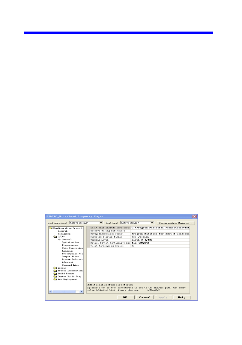
Digital Oscilloscope Series
224
VISA Examples
VC++ Example
Environment: Win7 32-bit, Visual Studio.
Description: Use National Instruments VISA to control the device with
USBTMC or TCP/IP access. Perform a write and read operation.
Steps:
1. Open Visual Studio, create a new VC++ win32 project.
2. Set the project environment to use the NI-VISA library. There are two ways to
use NI-VISA, static or automatic:
a) Static:
Find the files visa.h, visatype.h, visa32.lib in the NI-VISA installation path,
copy them to your project, and add them into the project. In the
projectname.cpp file, add the follow two lines:
#include "visa.h"
#pragma comment(lib,"visa32.lib")
b) Automatic:
Set the .h file include directory, the NI-VISA install path, in our computer
we set the path is: C:\Program Files\IVI Foundation \VISA\WinNT\include.
Set this path to project---properties---c/c++---General---Additional Include
Directories: See the picture.
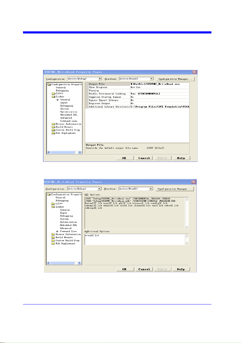
Digital Oscilloscope Series
225
Set lib path set lib file:
Set lib path: the NI-VISA install path, in our computer we set the path is :
C:\Program Files\IVI Foundation\VISA\WinNT
\lib\msc. Set this path to project---properties---Linker---General---
Additional Library Directories: as shown in the pictures below.
Set lib file:project---properties---Linker---Command Line---Additional
Options: visa32.lib
Include visa.h file in the projectname.cpp file:
#include <visa.h>

Digital Oscilloscope Series
226
3. Coding:
a) USBTMC:
Int Usbtmc_test()
{
/* This code demonstrates sending synchronous read & write commands */
/* to an USB Test & Measurement Class (USBTMC) instrument using */
/* NI-VISA */
/* The example writes the "*IDN?\n" string to all the USBTMC */
/* devices connected to the system and attempts to read back */
/* results using the write and read functions. */
/* The general flow of the code is */
/* Open Resource Manager */
/* Open VISA Session to an Instrument */
/* Write the Identification Query Using viPrintf */
/* Try to Read a Response With viScanf */
/* Close the VISA Session */
/***********************************************************/
ViSession defaultRM;
ViSession instr;
ViUInt32 numInstrs;
ViFindList findList;
ViUInt32 retCount;
ViUInt32 writeCount;
ViStatus status;
Char instrResourceString[VI_FIND_BUFLEN];
Unsigned char buffer[100];
Char stringinput[512];
Int i;
/** First we must call viOpenDefaultRM to get the manager
* handle. We will store this handle in defaultRM.*/
status=viOpenDefaultRM (&defaultRM);

Digital Oscilloscope Series
227
if (status<VI_SUCCESS)
{
printf ("Could not open a session to the VISA Resource Manager!\n");
return status;
}
/* Find all the USB TMC VISA resources in our system and store the number of
resources in the system in numInstrs. */
status = viFindRsrc (defaultRM, "USB?*INSTR", &findList, &numInstrs,
instrResourceString);
if (status<VI_SUCCESS)
{
printf ("An error occurred while finding resources.\nHit enter to continue.");
fflush(stdin);
getchar();
viClose (defaultRM);
return status;
}
/** Now we will open VISA sessions to all USB TMC instruments.
* We must use the handle from viOpenDefaultRM and we must
* also use a string that indicates which instrument to open. This
* is called the instrument descriptor. The format for this string
* can be found in the function panel by right clicking on the
* descriptor parameter. After opening a session to the
* device, we will get a handle to the instrument which we
* will use in later VISA functions. The AccessMode and Timeout
* parameters in this function are reserved for future
* functionality. These two parameters are given the value VI_NULL.*/
for (i=0; i<numInstrs; i++)
{
if (i> 0)
{

Digital Oscilloscope Series
228
viFindNext (findList, instrResourceString);
}
status = viOpen (defaultRM, instrResourceString, VI_NULL, VI_NULL, &instr);
if (status<VI_SUCCESS)
{
printf ("Cannot open a session to the device %d.\n", i+1);
continue;
}
/* * At this point we now have a session open to the USB TMC instrument.
* We will now use the viPrintf function to send the device the string "*IDN?\n",
* asking for the device's identification. */
char * cmmand ="*IDN?\n";
status = viPrintf (instr, cmmand);
if (status<VI_SUCCESS)
{
printf ("Error writing to the device %d.\n", i+1);
status = viClose (instr);
continue;
}
/** Now we will attempt to read back a response from the device to
* the identification query that was sent. We will use the viScanf
* function to acquire the data.
* After the data has been read the response is displayed.*/
status = viScanf(instr, "%t", buffer);
if (status<VI_SUCCESS)
{
printf ("Error reading a response from the device %d.\n", i+1);
}
else
{
printf ("\nDevice %d: %*s\n", i+1,retCount, buffer);
}

Digital Oscilloscope Series
229
status = viClose (instr);
}
/** Now we will close the session to the instrument using
* viClose. This operation frees all system resources. */
status = viClose (defaultRM);
printf("Press 'Enter' to exit.");
fflush(stdin);
getchar();
return 0;
}
b) TCP/IP:
int TCP_IP_Test(char *pIP)
{
char outputBuffer[VI_FIND_BUFLEN];
ViSession defaultRM, instr;
ViStatus status;
ViUInt32 count;
ViUInt16 portNo;
/* First we will need to open the default resource manager. */
status = viOpenDefaultRM (&defaultRM);
if (status<VI_SUCCESS)
{
printf("Could not open a session to the VISA Resource Manager!\n");
}
/* Now we will open a session via TCP/IP device */
char head[256] ="TCPIP0::";
char tail[] ="::INSTR";
char resource [256];
strcat(head,pIP);

Digital Oscilloscope Series
230
strcat(head,tail);
status = viOpen (defaultRM, head, VI_LOAD_CONFIG, VI_NULL, &instr);
if (status<VI_SUCCESS)
{
printf ("An error occurred opening the session\n");
viClose(defaultRM);
}
status = viPrintf(instr, "*idn?\n");
status = viScanf(instr, "%t", outputBuffer);
if (status<VI_SUCCESS)
{
printf("viRead failed with error code: %x \n",status);
viClose(defaultRM);
}
else
{
printf ("\ndata read from device: %*s\n", 0,outputBuffer);
}
status = viClose (instr);
status = viClose (defaultRM);
printf("Press 'Enter' to exit.");
fflush(stdin);
getchar();
return 0;
}
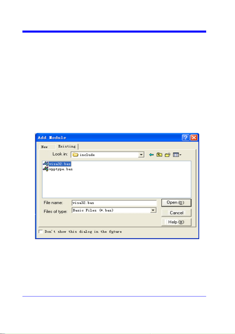
Digital Oscilloscope Series
231
VB Example
Environment: Windows7 32-bit, Microsoft Visual Basic 6.0
Description: The function of this example: Use the NI-VISA, to control
the device with USBTMC and TCP/IP access to do a write and read.
Steps:
1. Open Visual Basic, and build a standard application program project.
2. Set the project environment to use the NI-VISA lib: Click the Existing
tab of Project>>Add Module, search the visa32.bas file in the ―include‖
folder under the NI-VISA installation path and add the file, as shown in
the figure below:
3. Coding:
a) USBTMC:
Private Function Usbtmc_test() As Long
' This code demonstrates sending synchronous read & write commands

Digital Oscilloscope Series
232
' to an USB Test & Measurement Class (USBTMC) instrument using
' NI-VISA
' The example writes the "*IDN?\n" string to all the USBTMC
' devices connected to the system and attempts to read back
' results using the write and read functions.
' The general flow of the code is
' Open Resource Manager
' Open VISA Session to an Instrument
' Write the Identification Query Using viWrite
' Try to Read a Response With viRead
' Close the VISA Session
Const MAX_CNT = 200
Dim defaultRM As Long
Dim instrsesn As Long
Dim numlnstrs As Long
Dim findList As Long
Dim retCount As Long
Dim writeCount As Long
Dim status As Long
Dim instrResourceString As String * VI_FIND_BUFLEN
Dim buffer As String * MAX_CNT
Dim i As Integer
' First we must call viOpenDefaultRM to get the manager
' handle. We will store this handle in defaultRM.
status = viOpenDefaultRM(defaultRM)
If (status < VI_SUCCESS) Then
Debug.Print "Could not open a session to the VISA Resource Manager!"
Usbtmc_test = status
ExitFunction
End If

Digital Oscilloscope Series
233
' Find all the USB TMC VISA resources in our system and store the
' number of resources in the system in numInstrs.
status=viFindRsrc(defaultRM,"USB?*INSTR",findList,numlnstrs,instrResourceString)
If (status < VI_SUCCESS) Then
Debug.Print "An error occurred while finding resources."
viClose (defaultRM)
Usbtmc_test = status
Exit Function
End If
' Now we will open VISA sessions to all USB TMC instruments.
' We must use the handle from viOpenDefaultRM and we must
' also use a string that indicates which instrument to open. This
' is called the instrument descriptor. The format for this string
' can be found in the function panel by right clicking on the
' descriptor parameter. After opening a session to the
' device, we will get a handle to the instrument which we
' will use in later VISA functions. The AccessMode and Timeout
' parameters in this function are reserved for future
' functionality. These two parameters are given the value VI_NULL.
For i = 0 To numInstrs
If (i > 0) Then
status = viFindNext(findList, instrResourceString)
End If
status = viOpen(defaultRM, instrResourceString, VI_NULL, VI_NULL, instrsesn)
If (status < VI_SUCCESS) Then
Debug.Print "Cannot open a session to the device ", i + 1
GoTo NextFind
End If
' At this point we now have a session open to the USB TMC instrument.

Digital Oscilloscope Series
234
' We will now use the viWrite function to send the device the string "*IDN?",
' asking for the device's identification.
status = viWrite(instrsesn, "*IDN?", 5, retCount)
If (status < VI_SUCCESS) Then
Debug.Print "Error writing to the device."
status = viClose(instrsesn)
GoTo NextFind
End If
' Now we will attempt to read back a response from the device to
' the identification query that was sent. We will use the viRead
' function to acquire the data.
' After the data has been read the response is displayed.
status = viRead(instrsesn, buffer, MAX_CNT, retCount)
If (status < VI_SUCCESS) Then
Debug.Print "Error reading a response from the device.", i + 1
Else
Debug.Print i + 1, retCount, buffer
End If
status = viClose(instrsesn)
Next i
' Now we will close the session to the instrument using
' viClose. This operation frees all system resources.
status = viClose(defaultRM)
Usbtmc_test = 0
End Function
b) TCP/IP:
Private Function TCP_IP_Test(ip As String) As Long

Digital Oscilloscope Series
235
Dim outputBuffer As String * VI_FIND_BUFLEN
Dim defaultRM As Long
Dim instrsesn As Long
Dim status As Long
Dim count As Long
' First we will need to open the default resource manager.
status = viOpenDefaultRM (defaultRM)
If (status < VI_SUCCESS) Then
Debug.Print "Could not open a session to the VISA Resource Manager!"
TCP_IP_Test = status
Exit Function
End If
' Now we will open a session via TCP/IP device
status = viOpen(defaultRM, "TCPIP0::" + ip + "::INSTR", VI_LOAD_CONFIG,
VI_NULL, instrsesn)
If (status < VI_SUCCESS) Then
Debug.Print "An error occurred opening the session"
viClose (defaultRM)
TCP_IP_Test = status
Exit Function
End If
status = viWrite(instrsesn, "*IDN?", 5, count)
If (status < VI_SUCCESS) Then
Debug.Print "Error writing to the device."
End If
status = viRead(instrsesn, outputBuffer, VI_FIND_BUFLEN, count)
If (status < VI_SUCCESS) Then
Debug.Print "Error reading a response from the device.", i + 1

Digital Oscilloscope Series
236
Else
Debug.Print "read from device:", outputBuffer
End If
status = viClose(instrsesn)
status = viClose(defaultRM)
TCP_IP_Test = 0
End Function

Digital Oscilloscope Series
237
MATLAB Example
Environment: Windows7 32-bit, MATLAB R2010b
Description: The function of this example: Use the NI-VISA, to control
the device with USBTMC or TCP/IP access to do a write and read.
Steps:
1. Open MATLAB, and modify the current directory. In this demo, the current
directory is modified to D:\USBTMC_TCPIP_Demo.
2. Click File>>New>>Script in the Matlab interface to create an empty M file.
3. Coding:
a) USBTMC:
function USBTMC_test()
% This code demonstrates sending synchronous read & write commands
% to an USB Test & Measurement Class (USBTMC) instrument using
% NI-VISA
%Create a VISA-USB object connected to a USB instrument
vu = visa('ni','USB0::0xF4EC::0xEE38::0123456789::INSTR');
%Open the VISA object created
fopen(vu);
%Send the string "*IDN?",asking for the device's identification.
fprintf(vu,'*IDN?');
%Request the data
outputbuffer = fscanf(vu);
disp(outputbuffer);
%Close the VISA object
fclose(vu);
delete(vu);
clear vu;
end
b) TCP/IP:

Digital Oscilloscope Series
238
function TCP_IP_test( IPstr )
% This code demonstrates sending synchronous read & write commands
% to an TCP/IP instrument using NI-VISA
%Create a VISA-TCPIP object connected to an instrument
%configured with IP address.
vt = visa('ni',['TCPIP0::',IPstr,'::INSTR']);
%Open the VISA object created
fopen(vt);
%Send the string "*IDN?",asking for the device's identification.
fprintf(vt,'*IDN?');
%Request the data
outputbuffer = fscanf(vt);
disp(outputbuffer);
%Close the VISA object
fclose(vt);
delete(vt);
clear vt;
end
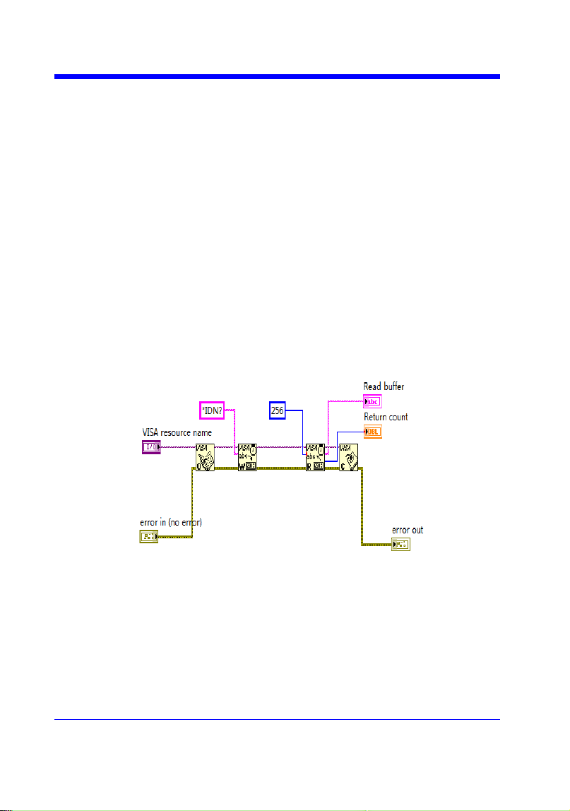
Digital Oscilloscope Series
239
LabVIEW Example
Environment: Windows7 32-bit, LabVIEW 2011
Description: The functions of this example: use the NI-VISA, to control
the device with USBTMC and TCP/IP access to do a write and read.
Steps:
1. Open LabVIEW, create a VI file.
2. Add controls. Right-click in the Front Panel interface, select and add
VISA resource name, error in, error out and some indicators from the
Controls column.
3. Open the Block Diagram interface. Right-click on the VISA resource
name and you can select and add the following functions from VISA
Palette from the pop-up menu: VISA Write, VISA Read, VISA Open and
VISA Close.
4. The connection is as shown in the figure below:
5. Select the device resource from the VISA Resource Name list box and run
the program.
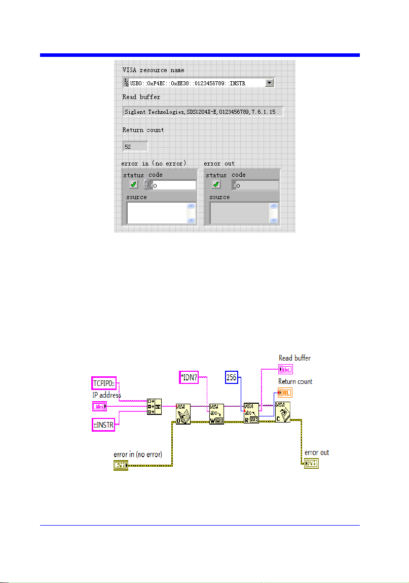
Digital Oscilloscope Series
240
In this example, the VI opens a VISA session to a USBTMC device, writes
a command to the device, and reads back the response. After all
communication is complete, the VI closes the VISA session.
6. Communicating with the device via TCP/IP is similar to USBTMC. But
you need to change VISA Write and VISA Read Function to Synchronous
I/O. The LabVIEW default is asynchronous I/O. Right-click the node and
select Synchronous I/O Mod>>Synchronous from the shortcut menu to
write or read data synchronously.
7. The connection is as shown in the figure below:
8. Input the IP address and run the program.
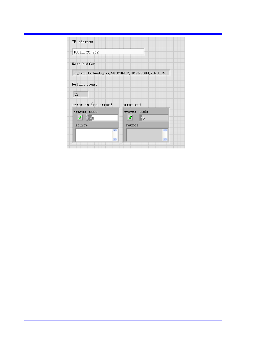
Digital Oscilloscope Series
241
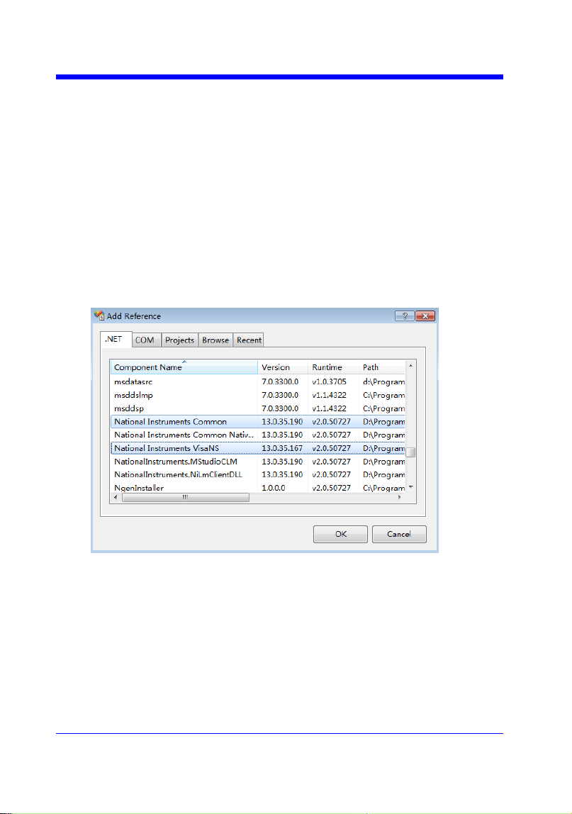
Digital Oscilloscope Series
242
C# Example
Environment: Windows7 32-bit, Visual Studio
Description: The functions of this example: use the NI-VISA, to control
the device with USBTMC or TCP/IP access to do a write and read.
Steps:
1. Open Visual Studio, create a new C# project.
2. Add References. Add NationalInstruments.Common.dll and
NationalInstruments.VisaNS.dll to the project. (Notice: you must install
the .NET Framework 3.5/4.0/4.5 Languages support when you install the
NI-VISA.)
3. Coding:
using System;
using System.Collections.Generic;
using System.Linq;
using System.Text;
using NationalInstruments.VisaNS;
namespace TestVisa

Digital Oscilloscope Series
243
{
class Program
{
static void Main(string[] args)
{
// Find all the USBTMC resources
string[]
usbRsrcStrings=ResourceManager.GetLocalManager().FindResources("
USB?*INSTR");
if (usbRsrcStrings.Length <= 0)
{
Console.WriteLine("Can not find USBTMC Device!");
return;
}
//Choose the first resource string to connect the device.
//You can input the address manually
//USBTMC:
//MessageBasedSession
mbSession=(MessageBasedSession)ResourceManager.GetLocalManager
().Open("USB0::0xF4EC::0xEE38::0123456789::INSTR");
/TCP IP:
//MessageBasedSession
mbSession=(MessageBasedSession)ResourceManager.GetLocalManager
().Open("TCPIP0::192.168.1.100::INSTR");
MessageBasedSession
mbSession=(MessageBasedSession)ResourceManager.GetLocalManager
().Open(usbRsrcStrings[0]);
mbSession.Write("*IDN?");
string result = mbSession.ReadString();
mbSession.Dispose();

Digital Oscilloscope Series
244
Console.WriteLine(result);
}
}
}

Digital Oscilloscope Series
245
Examples of Using Sockets
Socket communication is a basic communication technology in computer
network. It allows applications to communicate through the standard network
protocol mechanism built by network hardware and operation system.
This method is a two-way communication between the instrument and the
computer through a fixed port number.
Note that SCPI strings are terminated with a ―\n‖ (new line) character.
Python Example
Python has a low-level networking module that provides access to the socket
interface. Python scripts can be written for sockets to do a variety of test and
measurement tasks.
Environment: Windows 7 32-bit, Python v2.7.5
Description: Open a socket, send a query, and repeat this loop for 10 times,
finally close the socket.
Below is the code of the script:
#!/usr/bin/env python
#-*- coding:utf-8 –*-
#-----------------------------------------------------------------------------
# The short script is a example that open a socket, sends a query,
# print the return message and closes the socket.
#-----------------------------------------------------------------------------
import socket # for sockets
import sys # for exit
import time # for sleep
#-----------------------------------------------------------------------------
remote_ip = "10.11.13.32" # should match the instrument‘s IP address
port = 5024 # the port number of the instrument service
count = 0

Digital Oscilloscope Series
246
def SocketConnect():
try:
#create an AF_INET, STREAM socket (TCP)
s = socket.socket(socket.AF_INET, socket.SOCK_STREAM)
except socket.error:
print ('Failed to create socket.')
sys.exit();
try:
#Connect to remote server
s.connect((remote_ip , port))
info = s.recv(4096)
print (info)
except socket.error:
print ('failed to connect to ip ' + remote_ip)
return s
def SocketQuery(Sock, cmd):
try :
#Send cmd string
Sock.sendall(cmd)
time.sleep(1)
except socket.error:
#Send failed
print ('Send failed')
sys.exit()
reply = Sock.recv(4096)
return reply
def SocketClose(Sock):
#close the socket
Sock.close()

Digital Oscilloscope Series
247
time.sleep(.300)
def main():
global remote_ip
global port
global count
# Body: send the SCPI commands *IDN? 10 times and print the return message
s = SocketConnect()
for i in range(10):
qStr = SocketQuery(s, b'*IDN?')
print (str(count) + ":: " + str(qStr))
count = count + 1
SocketClose(s)
input('Press "Enter" to exit')
if __name__ == '__main__':
proc = main()

Digital Oscilloscope Series
248
C Example
int MySocket;
if((MySocket=socket(PF_INET,SOCK_STREAM,0))==-1)
{
exit(1);
}
struct in_addr
{
unsigned long s_addr;
};
struct sockaddr_in
{
short int sin_family; // Address family
unsigned short int sin_port; // Port number
struct in_addr sin_addr; // Internet address
unsigned char sin_zero[8]; // Padding
};
struct sockaddr_in MyAddress;
// Initialize the whole structure to zero
memset(&MyAddress,0,sizeof(struct sockaddr_in));
// Then set the individual fields
MyAddress.sin_family=PF_INET; // IPv4
MyAddress.sin_port=htons(5025); // Port number used by most instruments
MyAddress.sin_addr.s_addr=inet_addr(―169.254.9.80‖); // IP Address
// Establish TCP connection
if(connect(MySocket,(struct sockaddr*)&MyAddress,sizeof(struct sockaddr_in))==-1)
{
exit(1);
}
// Send SCPI command
if(send(MySocket,‖*IDN?\n‖,6,0)==-1)
{
exit(1);
}
// Read response
char buffer[200];
int actual;
if((actual=recv(MySocket,&buffer[0],200,0))==-1)
{
exit(1);
}

Digital Oscilloscope Series
249
buffer[actual]=0; // Add zero character (C string)
printf(―Instrument ID: %s\n‖,buffer);
// Close socket
if(close(MySocket)==-1)
{
exit(1);
}

Digital Oscilloscope Series
250
Common Command Examples
This section lists the programming instances of common commands.
Environment: Windows 7 32-bit, Python v3.4.3, pyvisa-1.7, Matplotlib-1.5.1
Read Waveform Data (WF) Example
import visa
import pylab as pl
def main():
_rm = visa.ResourceManager()
sds = _rm.open_resource("USB0::0xF4EC::0xEE38::0123456789::INSTR")
sds.write("chdr off")
vdiv = sds.query("c1:vdiv?")
ofst = sds.query("c1:ofst?")
tdiv = sds.query("tdiv?")
sara = sds.query("sara?")
sara_unit = {'G':1E9,'M':1E6,'k':1E3}
for unit in sara_unit.keys():
if sara.find(unit)!=-1:
sara = sara.split(unit)
sara = float(sara[0])*sara_unit[unit]
break
sara = float(sara)
sds.timeout = 30000 #default value is 2000(2s)
sds.chunk_size = 20*1024*1024 #default value is 20*1024(20k bytes)
sds.write("c1:wf? dat2")
recv = list(sds.read_raw())[15:]
recv.pop()
recv.pop()
volt_value = []
for data in recv:
if data > 127:
data = data - 255
else:
pass
volt_value.append(data)
time_value = []
for idx in range(0,len(volt_value)):
volt_value[idx] = volt_value[idx]/25*float(vdiv)-float(ofst)
time_data = -(float(tdiv)*14/2)+idx*(1/sara)
time_value.append(time_data)

Digital Oscilloscope Series
251
pl.figure(figsize=(7,5))
pl.plot(time_value,volt_value,markersize=2,label=u"Y-T")
pl.legend()
pl.grid()
pl.show()
if __name__=='__main__':
main()
Read Waveform Data of Digital Example
import visa
import pylab as pl
def get_char_bit(char,n):
return (char >> n) & 1
def main():
_rm = visa.ResourceManager()
sds = _rm.open_resource("USB0::0xF4EC::0xEE38::0123456789::INSTR")
sds.write("chdr off")
tdiv = sds.query("tdiv?")
sara = sds.query("di:sara?")
sara_unit = {'G':1E9,'M':1E6,'k':1E3}
for unit in sara_unit.keys():
if sara.find(unit)!=-1:
sara = sara.split(unit)
sara = float(sara[0])*sara_unit[unit]
break
sara = float(sara)
sds.timeout = 30000 #default value is 2000(2s)
sds.chunk_size = 20*1024*1024 #default value is 20*1024(20k bytes)
sds.write("d0:wf? dat2")
recv = list(sds.read_raw())[15:]
recv.pop()
recv.pop()
volt_value = []
data =bytearray(recv)
for char in data:
for i in range(0,8):
volt_value.append(get_char_bit(char,i))
print(len(volt_value))
time_value = []
for idx in range(0,len(volt_value)):
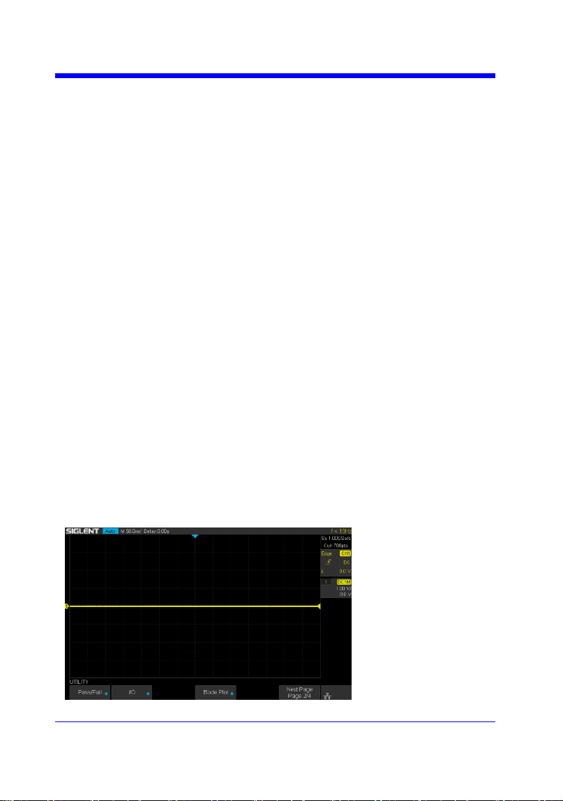
Digital Oscilloscope Series
252
time_data = -(float(tdiv)*14/2)+idx*(1/sara)
time_value.append(time_data)
pl.figure(figsize=(7,5))
pl.ylim(-1,2)
pl.plot(time_value,volt_value,markersize=2,label=u"Y-T")
pl.legend()
pl.grid()
pl.show()
if __name__=='__main__':
main()
Screen Dump (SCDP) Example
import visa
def main():
_rm = visa.ResourceManager()
sds = _rm.open_resource("USB0::0xF4EC::0xEE38::0123456789::INSTR")
file_name = "F:\\SCDP.bmp"
sds.write("SCDP")
result_str = sds.read_raw()
f = open(file_name,'wb')
f.write(result_str)
f.flush()
f.close()
if __name__=='__main__':
main()
Then you can open the file as shown below:

Digital Oscilloscope Series
253
Index
A
ACQUIRE_WAY, ACQW, Command/Query, 28
ARBWAVE, ARWV, Command, 193
ARM_ACQUISITION, ARM, Command, 25
ATTENUATION, ATTN, Command/Query, 41
AUTO_CALIBRATE, ACAL, Command/Query, 200
AUTO_SETUP, ASET, Command, 39
AUTO_TYPESET, AUTTS, Command/Query, 201
AVERAGE_ACQUIRE, AVGA, Command/Query, 30
B
BANDWIDTH_LIMIT, BWL, Command/Query, 42
BUZZER, BUZZ, Command/ Query, 150
C
CAL?, Query, 149
COMM_HEADER, CHDR, Command/Query, 23
COMM_NET, CONET, Command/Query, 151
COUNTER, COUN, Command/Query, 203
COUPLING, CPL, Command/Query, 43
CURSOR_AUTO, CRAU, Command, 204
CURSOR_MEASURE, CRMS, Command/Query, 51
CURSOR_SET, CRST, Command/Query, 53
CURSOR_TYPE, CRTY, Command/Query, 55
CURSOR_VALUE?, CRVA?,Query, 56
CUSTOM, CUS, Command/Query, 66
CSV_SAVE, CSVS, Command/Query, 205
CYMOMETER, CYMT, Query, 97
D
DATE, Command/Query, 208
DEFINE, DEF, Command/Query, 80
DIGITAL_CHANNEL, DGCH, Command/Query, 59
DIGITAL_STATE, DGST, Command/Query, 60
DIGITAL_THR, DGTH, Command/Query, 61
DOT_JOIN, DTJN, Command/Query, 69
F
FFT_CENTER, FFTC, Command/Query, 86
FFT_FULLSCREEN, FFTF, Command/Query, 88
FFT_POSITION, FFTP, Command/Query, 89

Digital Oscilloscope Series
254
FFT_SCALE, FFTS, Command/Query, 91
FFT_TDIV?, FFTT?, Query, 93
FFT_UNIT, FFTU, Command/Query, 94
FFT_WINDOW, FFTW, Command/Query, 95
FFT_ZOOM, FFTZ, Command/Query, 210
FILTER, FILT, Command/Query, 211
FILT_SET, FILTS, Command/Query, 212
FRAME_SET, FRAM, Command, 75
FRAME_TIME?, FTIM?, Query, 76
G
GRID_DISPLAY, GRDS, Command/Query, 70
H
HOR_MAGNIFY, HMAG, Command/Query, 157
HOR_POSITION, HPOS, Command/Query, 159
HISTORY_LIST, HLST, Command/Query, 78
HISTORY_MODE, HSMD, Command/Query, 77
I
IDN?, Query, 19
INTENSITY, INTS, Command/Query, 71
INR?, Query, 146
INVERT_SET, INVS, Command/Query, 49/82
M
MEASURE_DELY, MEAD, Command/Query, 99
MENU, MENU, Command/Query, 72
MEMORY_SIZE, MSIZ, Command/Query, 31
MATH_VERT_DIV, MTVD, Command/Query, 83
MATH_VERT_POS, MTVP, Command/Query, 85
O
OFFSET, OFST, Command/Query, 44
OPC, Command, 20
P
PANEL_SETUP, PNSU, Command/Query, 140
PARAMETER_CLR, PACL, Command, 111
PARAMETER_CUSTOM, PACU, Command, 102
PARAMETER_VALUE?, PAVA?, Query, 105
PEAK_DETECT, PDET, Command/Query, 214
PERSIST, PERS, Command/Query, 217
PERSIST_SETUP, PESU, Command/Query, 73

Digital Oscilloscope Series
255
PF_BUFFER, PFBF, Command/Query, 112
PF_CONTROL, PFCT, Command/Query, 215
PF_CREATEM, PFCM, Command, 113
PF_DATEDIS?, PFDD?, Query, 114
PF_DISPLAY, PFDS, Command/Query, 115
PF_ENABLE, PFEN, Command/Query, 116
PF_FAIL_STOP, PFFS, Command/Query, 117
PF_OPERATION, PFOP, Command/Query, 119
PF_SET, PFST, Command/Query, 121
PF_SOURCE, PFSC, Command/Query, 120
PRODUCT?, PROD?, Query, 194
R
RCL, Command, 125
RECALL, REC, Command, 218
RECALL_PANEL, RCPN, Command, 126
REF_CLOSE, REFCL, Command, 129
REF_DISPALY, REFDS, Command/Query, 130
REF_LOCATION, REFLA, Command/Query, 131
REF_POISITION, REFPO, Command/Query, 132
REF_SAVE, REFSA, Command, 134
REF_SCLALE, REFSC, Command/Query, 135
REF_SET, REFS, Command/Query, 219
REF_SOURCE, REFSR, Command/Query, 137
RST, Command, 21
S
SAMPLE_NUM?, SANU?, Query, 35
SAMPLE_RATE?, SARA?, Query, 33
SAMPLE_STATUS?, SAST?, Query, 32
SAV, Command, 139
SCREEN_DUMP, SCDP, Query, 123
SCREEN_SAVE, SCSV, Command/Query, 152
SET50, Command, 162
SINXX_SAMPLE, SXSA, Command/Query, 36
SKEW, Command, 45
STORELIST?, STL?, Query, 195
STOP, Command, 27
STORE_PANEL, STPN, Command, 142
SWITCH, SW, Command/Query, 63
T
THRESHOLD_MODE, TSM, Command/Query, 65
TIME_DIV, TDIV, Command/Query, 154
TRACE, TRA, Command/Query, 46/64

Digital Oscilloscope Series
256
TRIG_COUPLING, TRCP, Command/Query, 163
TRIG_DELAY, TRDL, Command/Query, 155
TRIG_LEVEL, TRLV, Command/Query, 164
TRIG_LEVEL2, TRLV2, Command/Query, 166
TRIG_MODE, TRMD, Command/Query, 168
TRIG_PATTERN, TRPA, Command/Query,170
TRIG_SELECT, TRSE, Command/Query, 171
TRIG_SLOPE, TRSL, Command/Query, 176
TRIG_WINDOW, TRWI, Command/Query, 177
U
UNIT, UNIT, Command/Query, 47
V
VOLT_DIV, VDIV, Command/Query, 48
VERT_POSITION, VPOS, Command/Query, 221
W
WAVEFORM?, WF?, Query, 179
WAVEFORM_SETUP, WFSU, Command/Query, 190
WAVEGENERATOR, WGEN, Command/Query, 196
WAVE_PARA?, WVPR?, Query,198
X
XY_DISPLAY, XYDS, Command/Query, 37