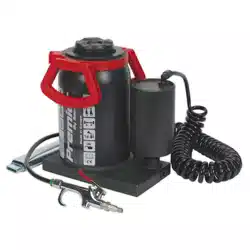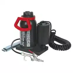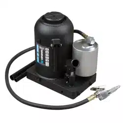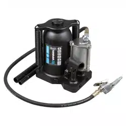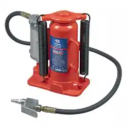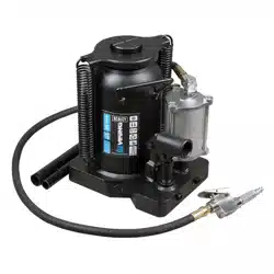
PREMIER VIKING AIR OPERATED BOTTLE JACKS
MODEL NO’S: AM20S, AM20SLE, AM30S, AM50S
Thank you for purchasing a Sealey product. Manufactured to a high standard, this product will, if used according to these instructions,
and properly maintained, give you years of trouble free performance.
IMPORTANT: PLEASE READ THESE INSTRUCTIONS CAREFULLY. NOTE THE SAFE OPERATIONAL REQUIREMENTS, WARNINGS & CAUTIONS.
USE THE PRODUCT CORRECTLY AND WITH CARE FOR THE PURPOSE FOR WHICH IT IS INTENDED. FAILURE TO DO SO MAY CAUSE
DAMAGE AND/OR PERSONAL INJURY AND WILL INVALIDATE THE WARRANTY. KEEP THESE INSTRUCTIONS SAFE FOR FUTURE USE.
1. SAFETY
8 Use jack only in accordance with this instruction manual.
9 It is necessary that the operator can watch the lifting device and the load during all movements.
9 The operator shall be provided with all the necessary information about training and about pumping and translating forces.
9 Ensure the jack is in sound condition and good working order. Take action for immediate repair or replacement of damaged parts. Use
genuine parts only. DO NOT modify the jack. The use of non-genuine parts may be dangerous and will invalidate the warranty. Replace
hoses ‘like for like’.
9 Locate the jack in a suitable, well lit working area. Keep working area clean and tidy and free from unrelated materials. Use jack on level
and solid ground, preferably concrete. Avoid tarmacadam as jack may sink in.
9 Chock wheels of vehicle.
9 Ensure the vehicle handbrake is engaged, engine is switched off and transmission is in gear (or “PARK” if automatic).
9 Ensure minimum distance of 0.5m between vehicle and static objects such as doors, walls, etc.
to allow for vehicle tilting.
9 Ensure all non-essential persons keep a safe distance whilst the jack is in use.
9 Ensure there are no passengers in the vehicle.
9 The operator of the jack must watch the jack and the load during all movements.
9 Place jack under only those lifting points recommended by vehicle manufacturer (see vehicle handbook).
9 Check that the lifting point is stable and centred on the jack saddle.
▲ DANGER: Use the jack for lifting only, NOT for supporting the lifted load.
WARNING! DO NOT work on, or under, a vehicle which is supported only by a jack (or jacks) - always use axle stands.
9 Ensure there are no persons or obstructions beneath the vehicle before lowering.
9 Use suitable axle stands under the vehicle before proceeding with any task.
9 Use a qualified person to lubricate and maintain the jack.
9 Ensure that only hydraulic jack oil is used in the jack.
8 DO NOT operate the jack if damaged.
8 DO NOT allow untrained persons to operate the jack.
8 DO NOT operate the jack when tired or under the influence of drugs, alcohol or intoxicating medication.
8 DO NOT exceed the rated capacity of the jack.
8 DO NOT allow the vehicle to move during lifting or lowering, or use the jack to move the vehicle.
8 DO NOT jack vehicle if there is a risk of spillage of fuel, battery acid, or other dangerous substances.
8 DO NOT work under the vehicle until appropriately rated axle stands have been correctly positioned.
8 DO NOT use the jack for purposes other than that for which it is intended.
8 DO NOT use with foodstuffs.
8 DO NOT top up hydraulic system with brake fluid. Use hydraulic jack oil only. (Sealey Part No: HJO500MLS or HJO5LS)
9 In the event of oil spillage ensure an oil spill kit is to hand. Consult Sealey website for Materials Safety Data Sheet for characteristics of
uids included with the product. Fireghting procedure/equipment should be in accordance with the Materials Safety Data Sheet.
8 DO NOT adjust the safety overload valve.
9 Lifting of persons is prohibited.
8 DO NOT use in severe weather conditions, risk assess the task. DO NOT use on ships.
9 Beware of static electrical shock from jack when used on some surfaces.
9 In the event of blockage stop using the jack and consult professional advice.
9 When not in use store jack, fully lowered, in a safe, dry, childproof area. Ensure if transported the jack is secured in an upright position.
8 DO NOT snatch the hose from the air supply, and DO NOT direct air from the air hose at yourself or others.
WARNING! Turn off air supply and de-pressurise the control nozzle before removing the pump unit from any installation or mobile system.
9 No modications shall be carried out which adversely aect the compliance of the jack with the standard.
9 Check the state of the markings and that the markings remain as the initial one.
9 Failure to comply with this instruction may damage the unit and will invalidate your warranty.
9 Lifetime of the jack: Manufactured to a high standard, this product will, if used according to these instructions, and properly
maintained, give you years of trouble free performance.
9 If the product needs to be scrapped it should be handled according to local regulations.
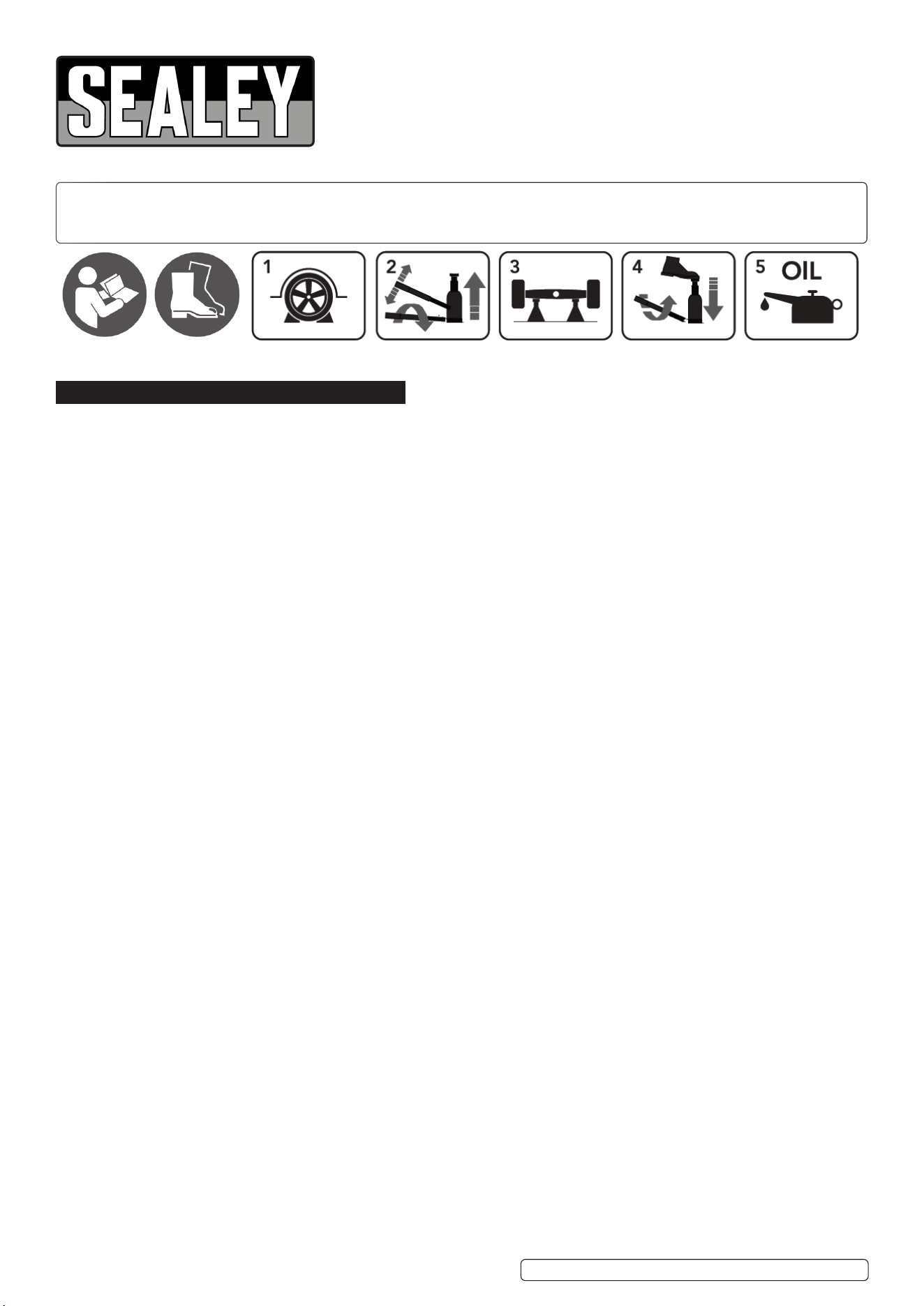
Refer to
instructions
Wear safety
footwear
Chock wheels Pump to raise Use axle stands
Lubricate here
To lower after use
Original Language Version
© Jack Sealey Limited
AM20S, AM20SLE, AM30S, AM50S Issue 5 (3) 08/03/24
2. INTRODUCTION
Air/Hydraulic bottle jack capable of both air assisted or manual operation. Fitted with safety overload valve. All steel, one-piece extra
thick base, reservoir and pump cylinder design gives added strength. Fully serviceable ram piston. Supplied with 90° rotating pump and
telescopic pump handle. Service kit readily available.
3. SPECIFICATION
MODEL NO. AM20S AM20SLE AM30S AM50S
Applicable Standard: EN 1494 EN 1494 EN 1494 EN 1494
Air Consumption: 7.5cfm 7.5cfm 7.5cfm 7.5cfm
Capacity: 20 Tonne 20 Tonne 30 Tonne 50 Tonne
Chassis Length x Width: 208 x 145mm 208 x 145mm 228 x 180mm 261.5 x 178mm
Maximum Height: 515mm 325mm 524mm 470mm
Minimum Height: 260mm 185mm 279mm 300mm
Nett Weight: 19kg 16kg 29kg 37kg
Piston Stroke: 150mm 80mm 150mm 170mm
Screw Extension: 105mm 60mm 95mm N/A
Working Pressure: 109-123psi 109-123psi 109-123psi 109-123psi
4. PREPARATION
4.1. CONNECT AIR SUPPLY
4.1.1. An in-line lter is recommended, drain daily. Drain compressor tank daily.
4.1.2. Before connecting air supply hose ensure trigger is not pressed down.
4.1.3. Ensure constant air pressure is maintained during operation: 109-123psi and a minimum air ow of 28L/min.
4.2. BLEED SYSTEM
4.2.1. Prior to using the jack, eliminate any air that may have accumulated in the system.
4.2.2. Position the lever in the release valve and turn once in an anti-clockwise direction.
4.2.3. Place the lever into the lever support and pump the jack several times to ensure internal lubrication and the elimination of accumulated
air. Alternatively, press trigger A of the valve briey.
4.2.4. Place the lever in release valve again and close it in a clockwise direction.
4.2.5. Jack is now ready for operation.
5. OPERATION
WARNING! Ensure that you read, understand and apply the safety instructions and warnings before use.
WARNING! Ensure that you have familiarised yourself thoroughly with the product and the hazards associated with improper use.
5.1. BEFORE FIRST USE
5.1.1. Before rst use, pour a teaspoon of good quality air tool lubricant into the hose quick coupler, then connect it to the air source, turn on
the air valve and allow to work for 3 seconds to evenly distribute the lubricant.
5.2. LIFTING
5.2.1. Use the slotted end of the handle to turn the release valve clockwise until it is rmly closed.
5.2.2. Apply the handbrake and chock all wheels to prevent any movement of the vehicle being lifted.
5.2.3. Place the jack into position and adjust as needed.
NOTE: check the vehicle owner’s manual for the location of recommended lifting points.
5.2.4. Connect the air quick coupler-male into the air quick coupler-female, then turn on the air valve.
5.2.5. Raise the load to the desired height.
5.2.6. Turn o the air valve and immediately USE AXLE STANDS with adequate capacity to support the load.
5.2.7. When an air source is not available, insert the big end of the handle into the handle bracket.
5.2.8. Pump it manually to raise the load to the desired height.
5.2.9. Immediately transfer the load to appropriate support devices such as axle stands.
5.3. LOWERING
WARNING! Be sure all tools and personnel are clear before lowering the load.
5.3.1. When work is done, raise the load enough to carefully remove the axle stands.
5.3.2. Slowly and carefully lower the load by turning the release valve anticlockwise (use the slotted end of the handle) in extremely small increments.
WARNING! Dangerous dynamic shock loads are created by quick opening and closing the release valve when the load is being
lowered. The resulting overload may cause hydraulic system failure which could cause severe personal injury and/or property damage.
6. MAINTENANCE
6.1. Jacks shall be maintained and repaired in accordance with the Sealey instructions. Such maintenance and repair shall be carried out
by qualied persons. DO NOT make any modications to the jack.
6.2. Check the state of the markings and that the marking remain as the initial one.
6.3. Clean the outside of the jack with a dry, clean and soft cloth.
6.4. Periodically lubricate the joints and all moving parts with a light oil as needed.
6.5. When not in use, store the jack in a dry location with the ram fully lowered.
6.6. BLEEDING THE HYDRAULIC SYSTEM
Bleed the hydraulic system to eliminate any air in the system if jack eciency drops or the jack doesn’t work
6.7. CHECK THE HYDRAULIC OIL
6.7.1. Place the jack in an upright position, completely lower the ram and remove the ller plug. If it is not completely full, ll with high quality
hydraulic jack oil to the lower rim of the ll hole, bleed away air from the hydraulic system as described in 4.2.
Top o with more hydraulic oil, then replace the ller plug.
Original Language Version
© Jack Sealey Limited
AM20S, AM20SLE, AM30S, AM50S Issue 5 (3) 08/03/24
Sealey Group, Kempson Way, Suffolk Business Park, Bury St Edmunds, Suffolk. IP32 7AR
01284 757500 sales@sealey.co.uk www.sealey.co.uk
Note: It is our policy to continually improve products and as such we reserve the right to alter data, specications and component parts without prior notice.
Important: No Liability is accepted for incorrect use of this product.
Warranty: Guarantee is 36 months from purchase date, proof of which is required for any claim.
ENVIRONMENT PROTECTION
Recycle unwanted materials instead of disposing of them as waste. All tools, accessories and packaging should be
sorted, taken to a recycling centre and disposed of in a manner which is compatible with the environment. When
the product becomes completely unserviceable and requires disposal, drain any uids (if applicable) into approved
containers and dispose of the product and uids according to local regulations.
REGISTER YOUR
PURCHASE HERE
6.7.2. For the best performance and longest life, completely replace the jack hydraulic oil at least once a year; with the ram fully lowered, remove the
oil ller plug, lay the jack on its side and drain the oil into a suitable container, then ll with high quality hydraulic jack oil. Reinstall the ller plug.
NOTE: dispose of hydraulic oil in accordance with local regulations.
6.8. It is recommended that an annual inspection be done by qualied technicians.
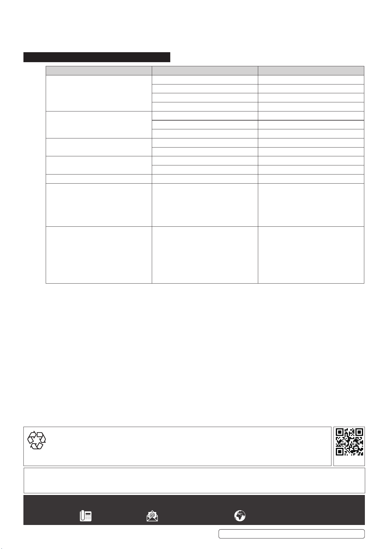
7. TROUBLESHOOTING
PROBLEM CAUSE SOLUTION
Jack will not lift load. Release valve not tightly closed. Close release valve rmly.
Overload condition. Remedy overload condition.
Air supply inadequate. Ensure adequate air supply.
Air trapped in system. Purge away air from system.
Jack will lift, but will not maintain pressure. Released valve not tightly closed. Close release valve rmly.
Overload condition. Remedy overload condition.
Hydraulic unit malfunction. Contact your dealer.
Will not lower after unloading. Reservoir overlled. Drain oil to proper level.
Linkages binding. Clean and lubricate moving parts.
Poor lifting performance. Hydraulic oil level low. Add oil to proper level.
Air trapped in system. Purge away air from system.
Will not lift to maximum height. Hydraulic oil level low. Add oil to proper level.
Poor manual performance Air trapped in system. Use the slotted end of the handle to turn
the release valve 1-1/2 turns anticlockwise
and remove the oil ller plug by gently
pulling. Insert the handle into the handle
bracket and pump it 10-15 times, then
replace the ller plug.
Poor air operated performance Air trapped in system. Connect the air inlet tting to air source,
use the slotted end of the handle to turn
the release valve 1-1/2 turns anticlockwise
and remove the oil ller plug by gently
pulling, turn on the air valve to let the
pump work for one minute, then replace
the ller plug.
Original Language Version
© Jack Sealey Limited
AM20S, AM20SLE, AM30S, AM50S Issue 5 (3) 08/03/24