Loading ...
Loading ...
Loading ...
9
TRANSITIONING TO 6-IN. DUCTS (FOR 110, 130 AND 150 CFM UNITS ONLY)
If using 6-in. ducts, install 5-in. to 6-in. transitions on the ports, and secure using duct tape only. If rigid ducting is used,
install a 12-in. section of fl exible duct between the transition and the rigid ducting (see above).
RIGID DUCTS
To prevent potential water leakage in cold side rigid ducting insulation, seal all rigid ducting joints with duct tape.
To avoid transmission of vibrations, always use a 12-inch section of fl exible duct to connect rigid ducts to the unit. To
connect insulated rigid ducts to the unit (cold side) using insulated fl exible ducts, follow instructions in section 2.5. To
connect regular rigid ducts (warm side) to the unit using non-insulated fl exible ducts, use a tie wrap.
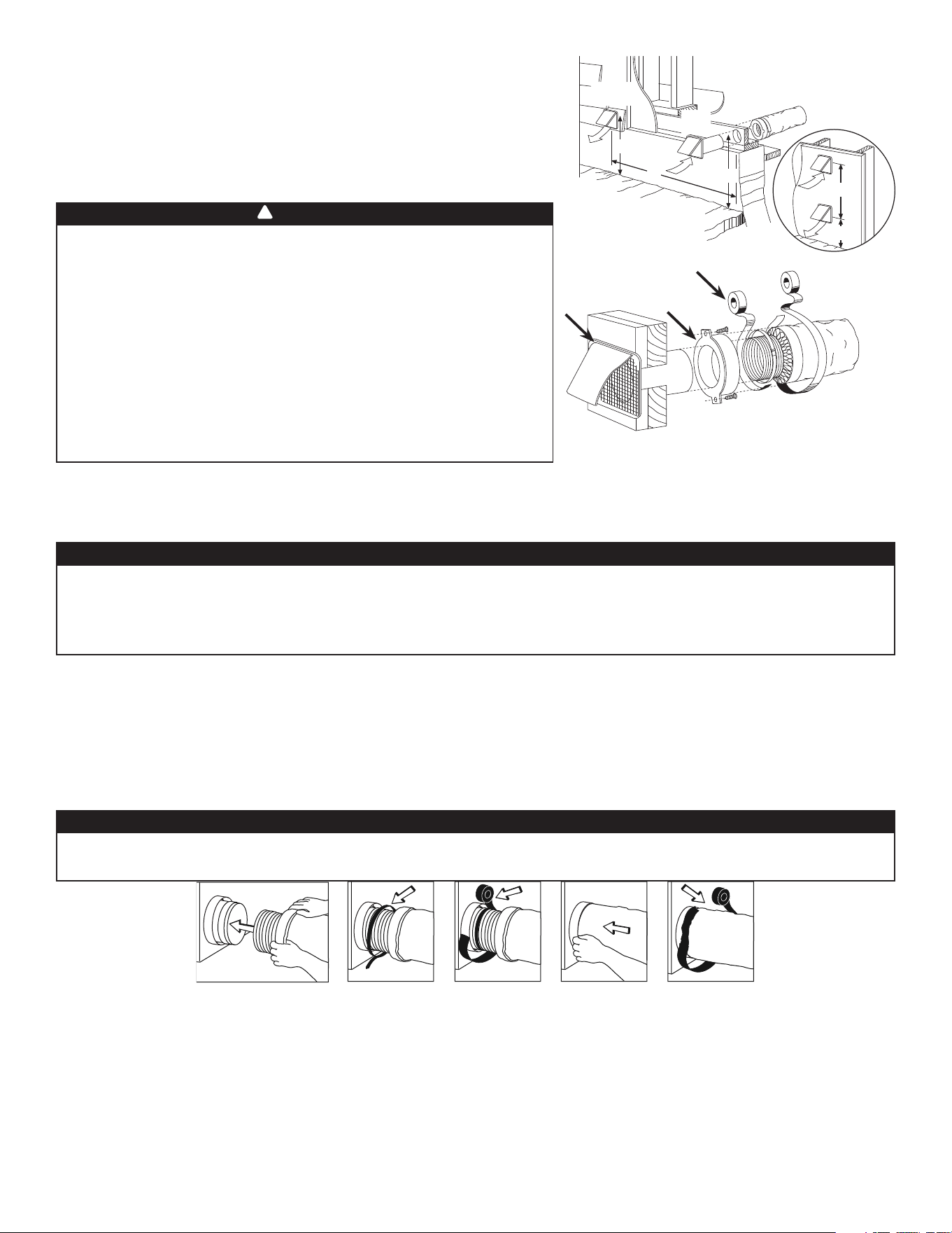
2.6 CONNECTING THE DUCTS TO THE UNIT
INSULATED FLEXIBLE DUCTS
Use the following procedure to connect the insulated fl exible ducts to the ports of the unit (exhaust to outside and fresh
air from outside).
1. Expose the fl exible duct by pulling back the insulation, and place it over the inner port ring.
2. Attach the fl exible duct to the port using a tie wrap.
3. Seal the joint using duct tape.
4. Pull the insulation and vapor barrier over the joint, tuck them between the inner and outer rings of the double collar and
fasten them in place using duct tape.
V
J0157
• If ducts have to go through an unconditioned space (e.g.: attic), always use insulated ducts to prevent
condensation formation inside and outside ducts, which could cause material damage and/or mold growth.
• Do not use screws to connect the ducts or transitions to the ports so as not to interfere with ports
inner dampers operation. A non-functioning damper could freeze the unit, which could cause damages.
CAUTION
The vapor barrier should remain intact and free of cracks or openings. An opening could produce condensation
inside or outside duct, which could cause material damage and/or mold growth in the long run.
CAUTION
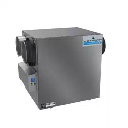
2.5 INSTALLING THE EXTERIOR HOODS
To avoid cross-contamination:
• Keep at least 6 feet between both hoods OR use approved combined
hoods model 14690.
• Install hood(s) at least at 18 inches away from the ground OR depth of
expected snow accumulation, whichever is greater.
Refer to illustration above for proper connection
method of the insulated ducts to the hoods.
“Anti-Gust Hoods” should be installed in regions
where a lot of snow is expected to fall.
VD0028
EXHAUST
HOOD*
INTAKE
HOOD
18”
18”
6’
6’
18”
OPTIONAL
DUCT LOCATION
TAPE AND DUCT TIE
CAULKING
Make sure intake hood is at least 6 feet (1.8 m) away from any
of the following:
• Dryer exhaust, high effi ciency central forced-air system vent,
central vacuum vent
• Gas meter exhaust, gas barbecue-grill
• Any exhaust from a combustion source
• Garbage bin and any other source of contamination.
Ignoring these recommendations could signifi cantly degrade the
quality of the incoming air which, in some cases, could result in
health consequences.
In the event of a confl ict between our conditions and local
requirements, the latter will have priority.
WARNING
!
NOTE: It is recommended to use 6" ducting instead of 5" ducting for 150H75NT, 150H75NS, 150E75NT and 150E75NS
units if required airfl ow is over 130 CFM. It will prevent having too high static pressure in the ducting.
CAULKING
*Do not install exhaust hood with non-return
damper since it can freeze in winter.
Loading ...
Loading ...
Loading ...