AIR OPERATED GREASE PUMP
MODEL NO: AK452X.V4, AK453X.V3
Thank you for purchasing a Sealey product. Manufactured to a high standard, this product will, if used according to these instructions,
and properly maintained, give you years of trouble free performance.
IMPORTANT: PLEASE READ THESE INSTRUCTIONS CAREFULLY. NOTE THE SAFE OPERATIONAL REQUIREMENTS, WARNINGS & CAUTIONS. USE
THE PRODUCT CORRECTLY AND WITH CARE FOR THE PURPOSE FOR WHICH IT IS INTENDED. FAILURE TO DO SO MAY CAUSE DAMAGE AND/OR
PERSONAL INJURY AND WILL INVALIDATE THE WARRANTY. KEEP THESE INSTRUCTIONS SAFE FOR FUTURE USE.
1. SAFETY
WARNING! Disconnect the grease pump from the air supply before changing accessories, servicing or performing any maintenance.
WARNING! Ensure correct air pressure is maintained and not exceeded. Recommended pressure 115psi.
WARNING! Turn off air supply and de-pressurise the control nozzle before removing the pump unit from any installation or mobile
system. Failure to comply with this instruction may damage the unit and will invalidate your warranty.
WARNING! DO NOT tamper with or open pump unit. To do so will invalidate your warranty.
9 Maintain pump in good condition (use an authorised service agent).
9 Replace or repair damaged parts. Check the grease bucket to ensure it is not damaged. A damaged grease bucket will cause the follower
plate to jam.
9 Use recommended parts only. Non authorised parts may be dangerous and will invalidate the warranty.
9 Wear appropriate protective clothing. When handling lubricants refer to manufacturer’s instructions and conform to local regulations.
9 Use the pump in an appropriate working area for its function. Keep area clean and tidy and free from unrelated materials and ensure
there is adequate lighting.
9 Keep air hose away from heat, oil and sharp edges. Check air hose for wear before each use, and ensure that all connections are secure.
9 Maintain correct balance & footing. Ensure floor is not slippery, wear non slip shoes.
9 Keep children and unauthorised persons away from the working area.
9 Dispose of waste grease in accordance with local authority regulations.
9 When not in use ensure the air supply is turned off.
9 When not in use, disconnect the unit from the air supply. Clean the unit and store in a dry, safe, childproof location.
8 DO NOT allow unauthorised persons to operate the pump.
8 DO NOT point grease gun at yourself, other persons or animals.
8 DO NOT pull the grease pump unit by the hoses, or yank the hose from the air supply.
8 DO NOT force the pump to achieve a task it was not designed to perform.
8 DO NOT operate the pump when you are tired, under the influence of alcohol, drugs or intoxicating medication.
2. i INTRODUCTION
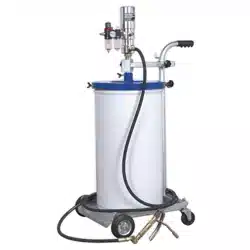
Fitted with high efficiency 50:1 air motor. Workshop tested reliability. Supplied with safety regulator to prevent over pressurisation of
pump unit. Fitted with a follower plate to prevent pump unit cavitation and ensure a smooth flow of grease. Includes SAE100R2AT rated
grease hose, z-swivel, control valve and bucket trolley. The AK452X.V4 and AK453X.V3 are designed for use with most popular multi-
purpose greases to NLGI No.2 specification made with light to medium base oil viscosities. The flow rate (delivery) performance will vary
dependant upon the lubricant viscosity, temperature, additives, and on the pipelines used.
3. i SPECIFICATION
Model Nos: ....................................... AK452X.V4, AL453X.V3
Bucket capacity AK452X.V4 ...........................................12.5kg
Bucket capacity AK453X.V3 ..........................................50.0kg
Maximum Air Pressure: ............................................... 150psi
Recommended Air Pressure: .......................................115psi
Delivery Pressure: ......................................................5000psi
Grease Delivery: ....................................................1100g/min
Air Consumption: ........................................................... 6cfm
Air inlet ........................................................... 1/4”BSP Female
Material outlet ................................................. 1/4”BSP Female
AK452X.V4 Nett Weight ...............................................19.03kg
AK453X.V3 Nett Weight ...............................................19.76kg
4. ASSEMBLY
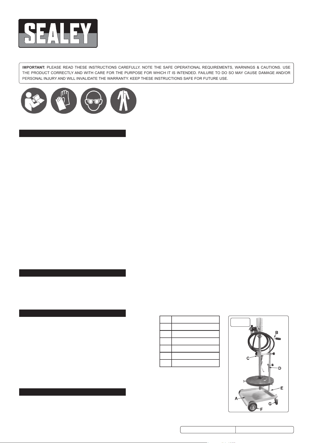
4.1. Contents.
4.1.1. Removeitemsfromcartonandidentifypiecesfromcontentslistaboveusingg.1and
g.2asareference.
4.1.2. Contact your supplier immediately if any pieces are missing or damaged.
AK452X.V4, AK453X.V3 Issue 3 (H, F) 06/07/18
Original Language Version
© Jack Sealey Limited
Refer to
instruction
manual
Wear protective
gloves
Wear eye
protection
fig.1
A PLATFORM
B HANDLE
C SUPPORT BRACKET
D SECURING HOOK
E GRUB SCREW
F WHEEL ASSY.
G CASTOR
Wear protective
clothing
4.2. Assemblingthetrolley(refertog.1).
4.2.1. Attach the wheels (F) and castors (G) to the platform (A) using the nuts and bolts
provided.
4.2.2. Slide the support bracket (C) then the securing hook (D) onto the handle (B).
Attach the handle (B) to the platform (A) and secure with the grub screw (E).
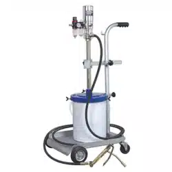
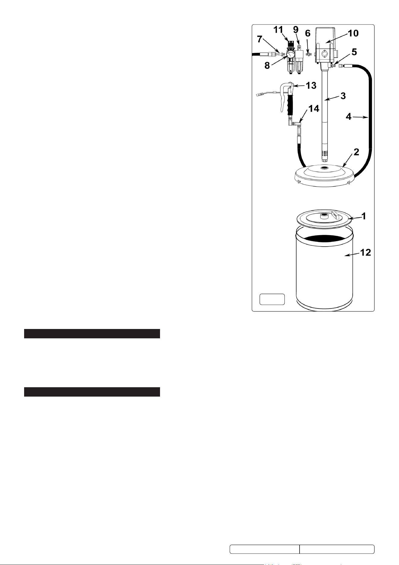
4.3. Assemblingthepumpunit(refertofig.2).
WARNING! Clean new delivery lines ensuring all metal shavings have been
removed before connecting the pump and control valves. Any dirt in the inlet hoses
will damage the unit and may invalidate your warranty.
NOTE: It is recommended that PTFE sealing tape is used on all connections.
4.3.1. Place the grease bucket (12) onto the platform of the trolley.
4.3.2. Remove the original lid supplied with the grease bucket and store it for future use.
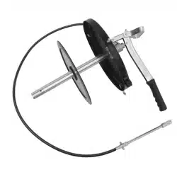
4.3.3. Insert the follower plate (1) into the top of the grease bucket (12) with the handle
uppermost and settle it down onto the surface of the grease. The follower plate
is drawn down by the suction of the air pump and compresses the grease during
operation to prevent air pockets.
4.3.4. Secure the grease bucket to the trolley by sliding the securing hook over the rim of
the grease bucket and locking with the hand screw.
4.3.5. Place the dust cover (2) onto the grease bucket (12), but do not secure.
4.3.6. Lower the pump assembly through the support bracket on the trolley.
4.3.7. Align the pump shaft (3) over the dust cover (2) and allow the shaft to pass through
the dust cover (2), and the follower plate (1) then sink down to the bottom of the
grease bucket (12).
4.3.8. Align the position of the trolley support bracket so that the pump shaft is vertical
and perpendicular to the trolley base and the support bracket is set to the correct
position.
4.3.9. Tighten the trolley support bracket hand screws and tighten the three butterfly
screws to secure the dust cover (2) to the grease bucket (12).
4.3.10. Connect the air regulator (11) and air oiler (9) together using the long bolts and
Nuts provided (The nuts slide into the recesses in the front and back of the
regulator body). Ensure that the air flow arrows moulded into the top of each unit
body are pointing in the same direction and that both arrows are pointing towards
the pump air inlet. The air oiler (9) should be situated between the air regulator (11)
and the pump (10).
4.3.11. Screw the circular pressure gauge (8) into which ever side of the regulator (11)
is most convenient for reading. Seal the unused mounting position using the
blanking plug provided.
4.3.12. Connect the regulator (11) assembly to the pump air inlet using the 1/4”BSP fitting
(6) provided.
4.3.13. Connect the Z-swivel (14) to the grease gun (13) and connect the grease hose (4)
to the Z-swivel (14). Connect the other end of the grease hose (4) to the grease
outlet (5) on the pump.
5. OPERATION
5.1. Turn the air pressure on and check there are no leaks in the system.
5.2. Adjust the air pressure using the air knob on top of the air regulator. Unlock the knob by pulling it upwards and turning it until the gauge
indicates the recommended operating pressure of 115psi. Push the knob down again to lock it. It is important to maintain the correct
operating pressure to ensure that the control valves and connectors are not damaged, and to prevent leakage in the delivery lines.
5.3. Prime unit by operating grease control valve until lubricant emerges from end of the gun. The unit is now ready for use.
5.4. When not in use, turn the air supply off and disconnect the unit from the air supply. Store in a safe, clean, dry, childproof location.
6. MAINTENANCE
WARNING! Disconnect the pump from the air line before attempting any service or maintenance. Replace or repair damaged parts.
Use genuine parts only. Non-authorised parts may be dangerous and will invalidate the warranty.
6.1. Air line lubricator. This unit is designed to automatically lubricate the pump through the air intake. The unit must be kept topped up
withgoodqualityairoil(Sealeyref:ATO/500500mlsizeorAT/10001ltrsize).Toadjusttheoilowturntheoilregulatorscrewon
thetopoftheunit.Turnanti-clockwisetoincreasetheowandclockwisetodecreasetheow.Theoilsuppliedtolubricatethepump
is minimal. For an initial setting turn adjusting screw on top of the unit fully home and then open by ¼ of a turn. To change and clean
theoilunitunscrewthebowlandretainthesealingring.Empty,clean,re-lltomaximumlineandreplaceensuringthesealingringis
ttedcorrectly.DO NOT overtighten the bowl. Contact your local Sealey service agent for parts and information.
6.2. Cleaning. Clean pump and air units with clean damp cloth. Mild detergents may be used to remove grease. DO NOT use solvents or
abrasives and DO NOT get the pump or air units wet.
6.3. For a full service, contact your local Sealey service agent.
WARNING! When exchanging a polycarbonate bowl ensure the suction tube is protected to avoid dirt particles being transmitted to a
new bowl. Always clean new delivery lines ensuring all metal shavings have been removed before connecting the pump and control
valves. Failure to do so may damage the unit and will invalidate your warranty.
Original Language Version
© Jack Sealey Limited
fig.2
AK452X.V4, AK453X.V3 Issue 3 (H, F) 06/07/18
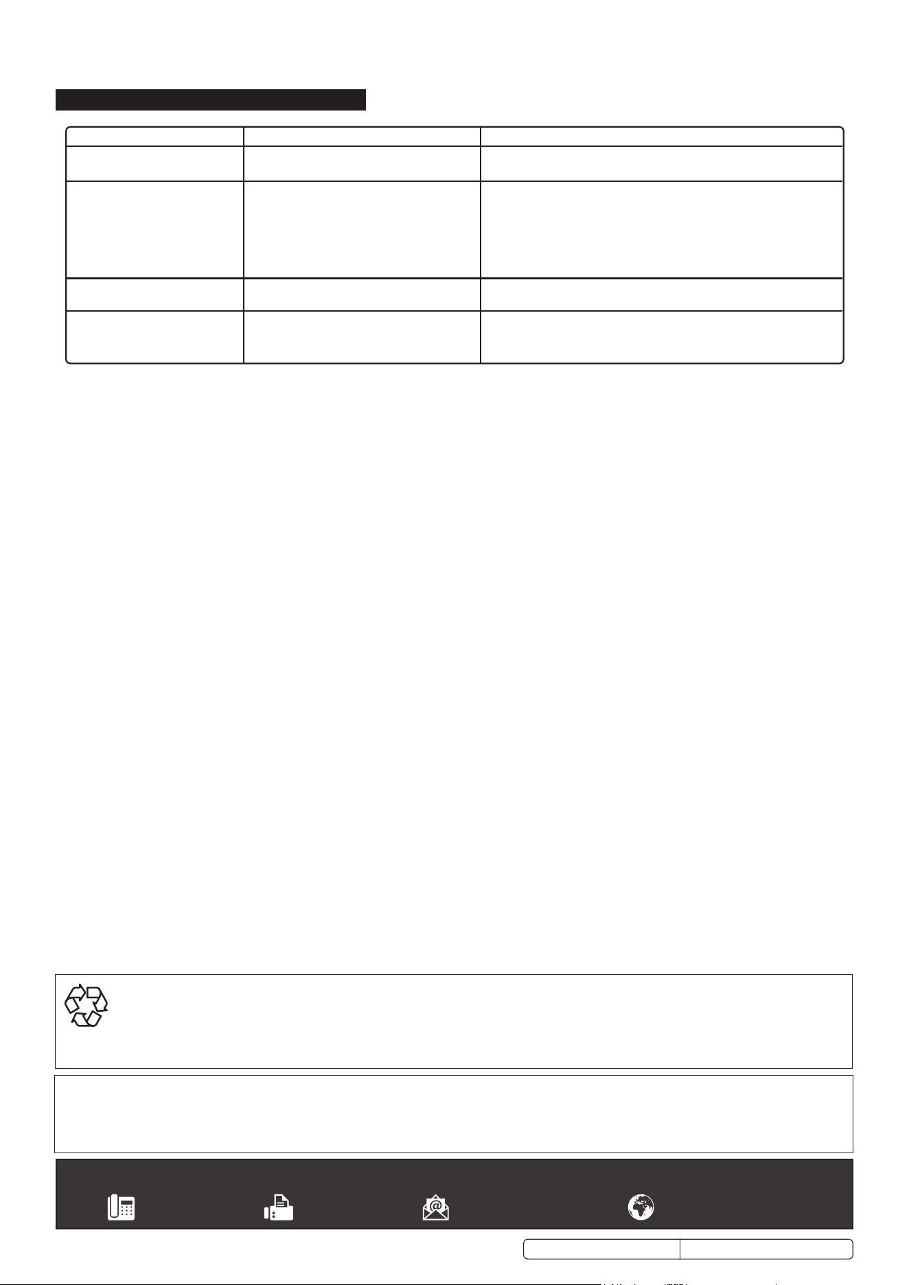
7. TROUBLESHOOTING
Original Language Version© Jack Sealey Limited
FAULT CAUSE REMEDY
Air motor runs slowly or not at all. Air pressure is too low.
Muerorlterisblockedordirty.
Adjust air pressure.
Removemuerand/orltercleanandreplace.
Air motor is running but pump is
too slow or not working at all.
Greaselterisblocked.
Grease viscosity too high.
Air pockets in grease container.
Grease container is dented
Removeandcleanlter
Move drum to warmer area to allow temperature of grease to rise above
15°C.
Viscosity too high. Temperature must be above 15°C. Compact the
grease by depressing the follower plate.
Push the follower plate past the dented area of the container.
Air motor is running but no
pressure is generated
'O' rings, washers or valves within pump are
damaged or dirty.
Clean or replace relevant components. Servicing by an approved Sealey
service agent recommended.
Airescapesfromthemuerwhen
the pump is not operating.
The plunger is damaged.
The 'O' rings or the distributor is damaged.
Replace plunger. Servicing by an approved Sealey service agent
recommended.
Replace parts using a complete repair kit.
AK452X.V4, AK453X.V3 Issue 3 (H, F) 06/07/18
Sealey Group, Kempson Way, Suffolk Business Park, Bury St Edmunds, Suffolk. IP32 7AR
01284 757500 01284 703534 sales@sealey.co.uk www.sealey.co.uk
ENVIRONMENT PROTECTION
Recycle unwanted materials instead of disposing of them as waste. All tools, accessories and packaging should be sorted, taken to
a recycling centre and disposed of in a manner which is compatible with the environment. When the product becomes completely
unserviceable and requires disposal, drain any fluids (if applicable) into approved containers and dispose of the product and fluids
according to local regulations.
Note: It is our policy to continually improve products and as such we reserve the right to alter data, specifications and component parts without prior
notice.
Important: No Liability is accepted for incorrect use of this product.
Warranty: Guarantee is 12 months from purchase date, proof of which is required for any claim.