8
Warranty Information
This one-year limited warranty is given to the end-user or the retail purchaser (referred to
this warranty as “Original Purchaser”) that it will be free from defects in material and
workmanship for a period of one year from the date of the purchase of the new product
(excluding accessory items such as power cords, cradle, memory card, adaptor, and cables).
This limited warranty does not cover any physical damage to, or misuse of, this product,
damage caused by improper installation; improper use; misuse; neglect; repair of cracked,
scratched, broken or modified cosmetics; or parts that have been altered or removed;
damages done by another device used with this product resulting from use of non-BOYO®-
brand parts. This warranty is VOID if you purchased this product as used, floor model
sample, or refurbished; if the product has been altered or modified in any way (including
but not limited to attempted repair without authorization from BOYO®- Vision Tech
America, Inc. and/or alteration/removal of the serial number).
For warranty information, visit: https://www.visiontechamerica.com/get-warranty
For technical support: Call: (888) 941-3060
Email: info@visiontechamerica.com
Visit: www.VisionTechAmerica.com
1
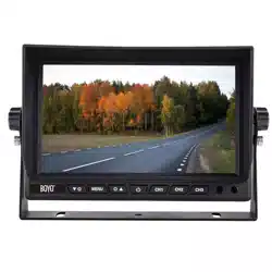
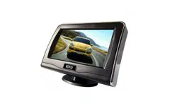
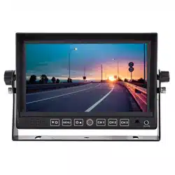
VTM7012FHD/VTM9003FHD
2
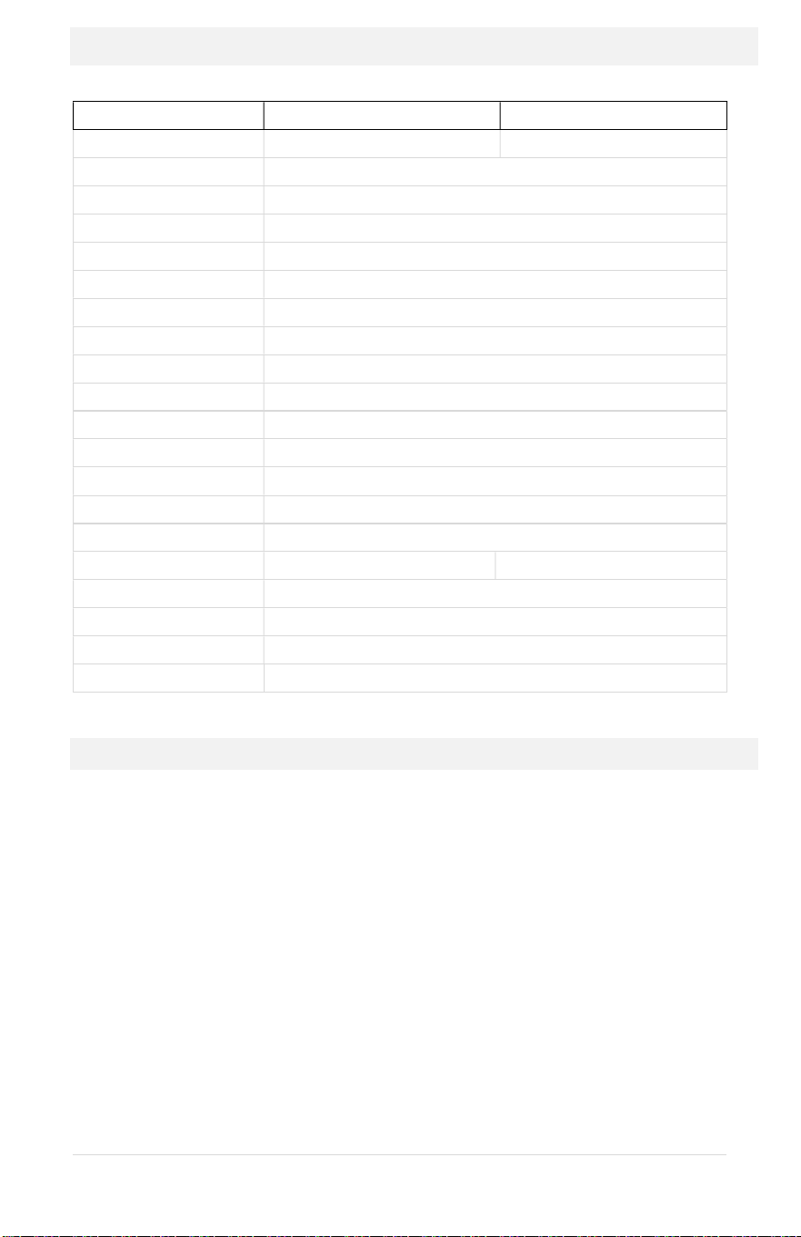
Product Features
Feature
VTM7012FHD
VTM9003FHD
Size
7” HD LCD
9” HD LCD
Resolution
1024 x 600
Aspect Ratio
16:9 wide screen
Video Inputs
3 (Ch1, Ch2, Ch3)
Audio Inputs
2 (Ch1, Ch2)
Display
Triggers
3 (Ch1, Ch2, Ch3)
Video Signal
1080P
AHD
/720P
AHD
/CVBS
-
Auto Switch
Video System
PAL
/
NTSC
-
Auto Switch
Speaker
Built
-
in
Mirror Image
Selectable for each channel
Parking Guidelines
Selectable for each channel
Trigger Delay
Configurable
Screen Flip
Horizontal / Vertical Flip
Auto Dimming
Yes
Remote Control
Included
Max. Current
<
500mA
@ 12VDC
Operating Power
12 ~ 24 VDC
Before Installation
Please check contents.
Perform bench test. Ensure the product is working before
installation by connecting the monitor and the camera to 12VDC.
Perform pre-install test, before mounting the monitor and the
camera. In very rare instances, a running engine causes
interference.
All issues should be resolved. So, when the monitor and the
cameras are mounted, wires are run and the power is turned on,
and a problem is encounter, it will be easy to troubleshoot the
problem.
7
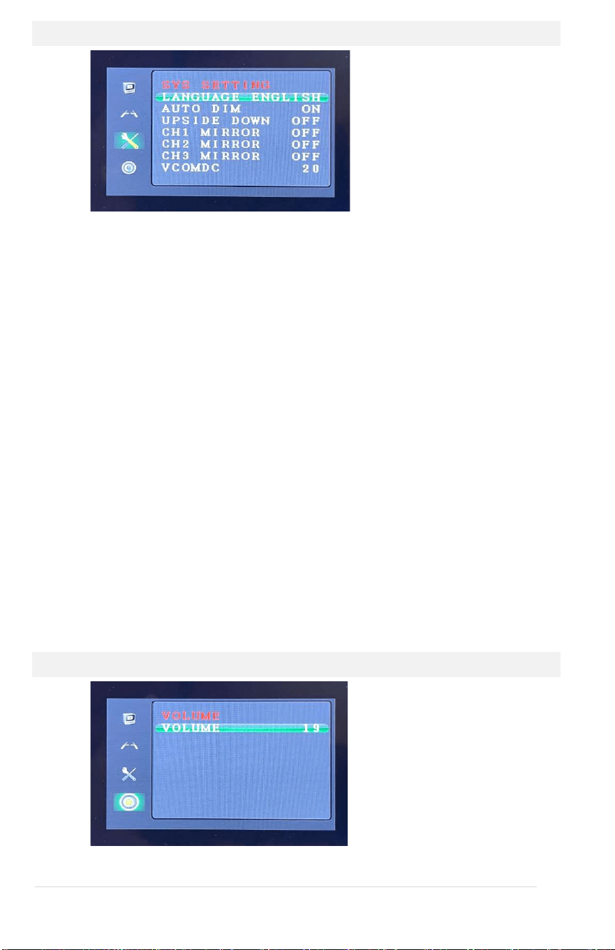
System Setting
1) LANGUAGE
English is the default. Japanese, Korean, Russian, and Chinese
are available.
2) AUTO DIM
VTM9003FHD feature. When turned on, the screen brightness
dims under low ambient light.
3) UPSIDE DOWN
Vertical display flip on or off
4) MIRROR
Horizontal display flip on or off. Used when a normal camera is
used as a backup camera. When a ‘normal’ camera is directed
toward rear, an object on the front-right side of the camera
will show on the right side of the display screen. Turn the
mirror ‘ON’ to display the object on the left side of the screen,
like mirror.
5) VCOMDC
When too much backlight come through the LCD, the black
screen with no image will look grey, not black. Decrease the
value. It controls amount backlight passes through LCD.
VOLUME Setting
1) VOLUME
Adjust speaker volume
6
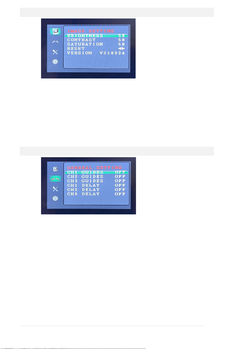
Image Setting
1) BRIGHTNESS, CONTRAST, SATURATION
Control display brightness and color
2) RESET
Reset the system to factory default
3) VERSION
The system version number
General Setting
1) GUIDELINES
Turn on or off the parking assist guidelines. Normally used with
the backup camera.
2) DELAY
Off or set between 1~10seconds. The delay setting determines
the number of seconds the video channel will stay on after
trigger line goes off. If the system is set off, then the monitor
will return to the previous state immediately once the trigger is
turned off. If delay is set 2s, then the monitor will return to the
previous state 2s later after finished reversing.
3
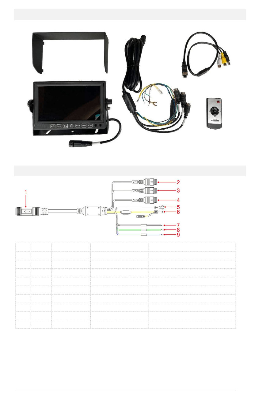
Contents
Wiring
1 Black 14-PIN power cable connector
2 Black 4-PIN male AV CH1 Input AHD 1080P, AHD 720P, or CVBS
3 Black 4-PIN male AV CH2 Input AHD 1080P, AHD 720P, or CVBS
4 Black 4-PIN male V CH3 Input AHD 1080P, AHD 720P, or CVBS
5 Black Wire GND
6 Red Wire ACC DC 12-24V positive pole
Yellow Wire Battery DC 12-24V positive pole
7 Brown Wire CH1 Trigger DC 12-24V positive pole
8 Green Wire CH2 Trigger DC 12-24V positive pole
9 Blue Wire CH3 Trigger DC 12-24V positive pole
A trigger wire is normally connected to a backup light, the left turn signal,
and the right turn signal. When a trigger wire becomes hot, it will display
the video input channel associated with the trigger.
Sunshade
Mo
n
itor
Power Harness
Remote
Control
1 x 4-Pin to RCA
Adapter
4
´ ¬®¯°±²³
É
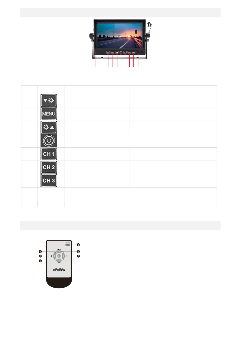
Buttons & Sensors
Default Menu Mode
¬
Down: move down in the menu setting
Enter OSD Menu Mode Next OSD Menu Item
®
Up: move up in menu setting
¯
Power: short press to turn on or off
°
Display Channel 1 Decrease Value
±
Display Channel 2 Increase Value
²
Display Channel 3
³
Remote control sensor
´
Dimmer sensor
É
Bracket knob
Remote Control
Ê Power key: short press to turn on or off
Ë VIDEO key: CH1, CH2, CH3 video channel
switching, to move up in menu setting
Ì Right key: increase volume, increase analog
value in the menu setting
Í MENU key: menu
Î Left key: decrease volume, decrease analog
value in the menu setting
Ï. MODE key: image mode switching, to move
down in menu setting
5
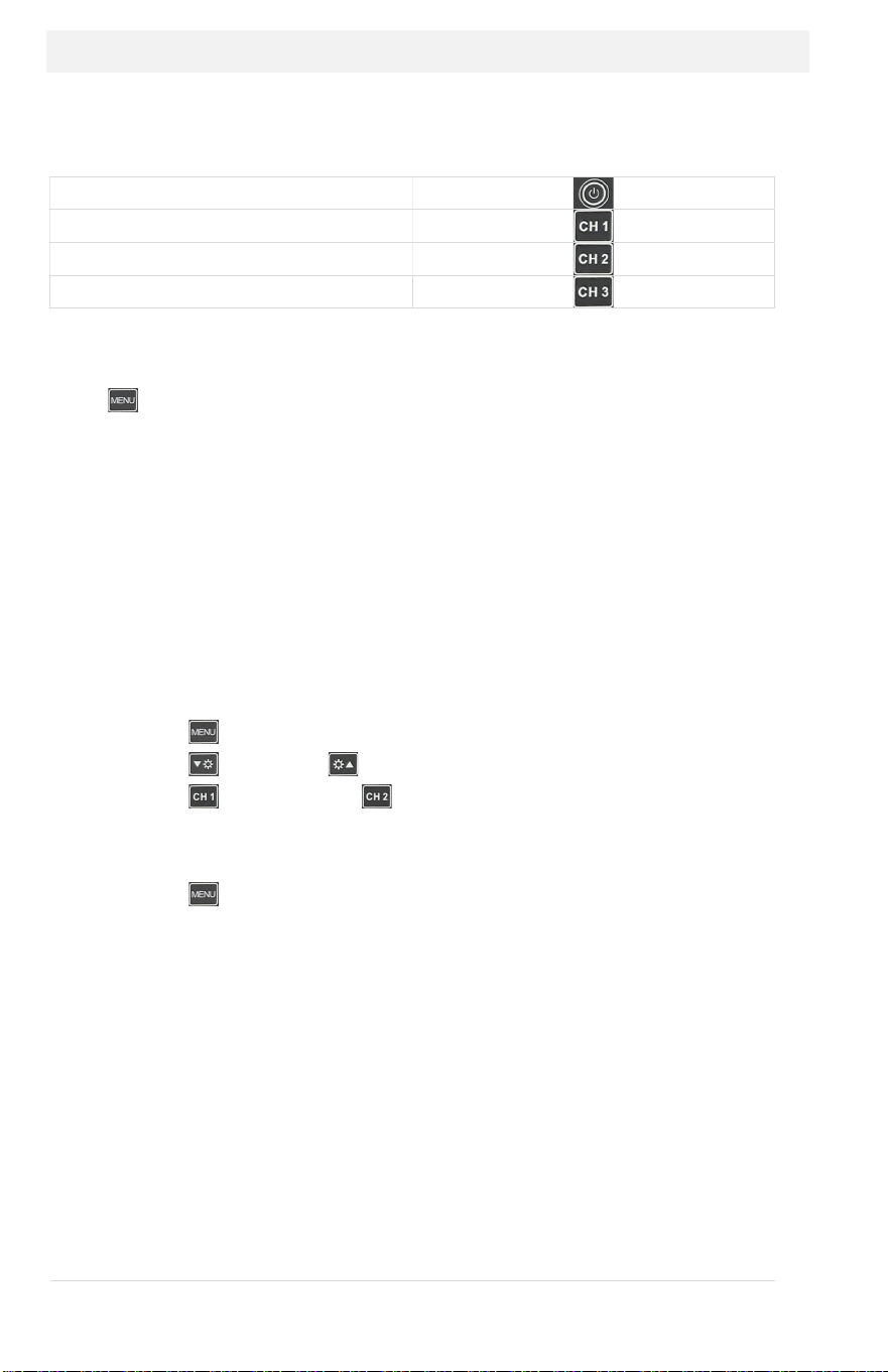
Operations: Using the Buttons
Default Mode
Press Button
To turn the display on or off
To display channel 1
To display channel 2
To display channel 3
OSD Setting Mode
Press (menu) to enter the OSD setting mode.
Repeated pressing of “MENU” button will cycle through
à Image Setting
à General Setting
à System Setting
à Volume Setting
To change the values:
1. Press (MENU) button to get to the right settings
2. Press (down) or (up) button to select the rows
3. Press (decrease) or (increase)
to “decrease” or “increase” value
or to turn “on” or “off”
4. Press (MENU) button to save new settings
4
´ ¬®¯°±²³
É
Buttons & Sensors
Default Menu Mode
¬
Down: move down in the menu setting
Enter OSD Menu Mode Next OSD Menu Item
®
Up: move up in menu setting
¯
Power: short press to turn on or off
°
Display Channel 1 Decrease Value
±
Display Channel 2 Increase Value
²
Display Channel 3
³
Remote control sensor
´
Dimmer sensor
É
Bracket knob
Remote Control
Ê Power key: short press to turn on or off
Ë VIDEO key: CH1, CH2, CH3 video channel
switching, to move up in menu setting
Ì Right key: increase volume, increase analog
value in the menu setting
Í MENU key: menu
Î Left key: decrease volume, decrease analog
value in the menu setting
Ï. MODE key: image mode switching, to move
down in menu setting
5
Operations: Using the Buttons
Default Mode
Press Button
To turn the display on or off
To display channel 1
To display channel 2
To display channel 3
OSD Setting Mode
Press (menu) to enter the OSD setting mode.
Repeated pressing of “MENU” button will cycle through
à Image Setting
à General Setting
à System Setting
à Volume Setting
To change the values:
1. Press (MENU) button to get to the right settings
2. Press (down) or (up) button to select the rows
3. Press (decrease) or (increase)
to “decrease” or “increase” value
or to turn “on” or “off”
4. Press (MENU) button to save new settings
6
Image Setting
1) BRIGHTNESS, CONTRAST, SATURATION
Control display brightness and color
2) RESET
Reset the system to factory default
3) VERSION
The system version number
General Setting
1) GUIDELINES
Turn on or off the parking assist guidelines. Normally used with
the backup camera.
2) DELAY
Off or set between 1~10seconds. The delay setting determines
the number of seconds the video channel will stay on after
trigger line goes off. If the system is set off, then the monitor
will return to the previous state immediately once the trigger is
turned off. If delay is set 2s, then the monitor will return to the
previous state 2s later after finished reversing.
3
Contents
Wiring
1 Black 14-PIN power cable connector
2 Black 4-PIN male AV CH1 Input AHD 1080P, AHD 720P, or CVBS
3 Black 4-PIN male AV CH2 Input AHD 1080P, AHD 720P, or CVBS
4 Black 4-PIN male V CH3 Input AHD 1080P, AHD 720P, or CVBS
5 Black Wire GND
6 Red Wire ACC DC 12-24V positive pole
Yellow Wire Battery DC 12-24V positive pole
7 Brown Wire CH1 Trigger DC 12-24V positive pole
8 Green Wire CH2 Trigger DC 12-24V positive pole
9 Blue Wire CH3 Trigger DC 12-24V positive pole
A trigger wire is normally connected to a backup light, the left turn signal,
and the right turn signal. When a trigger wire becomes hot, it will display
the video input channel associated with the trigger.
Sunshade
Mo
n
itor
Power Harness
Remote
Control
1 x 4-Pin to RCA
Adapter
2
Product Features
Feature
VTM7012FHD
VTM9003FHD
Size
7” HD LCD
9” HD LCD
Resolution
1024 x 600
Aspect Ratio
16:9 wide screen
Video Inputs
3 (Ch1, Ch2, Ch3)
Audio Inputs
2 (Ch1, Ch2)
Display
Triggers
3 (Ch1, Ch2, Ch3)
Video Signal
1080P
AHD
/720P
AHD
/CVBS
-
Auto Switch
Video System
PAL
/
NTSC
-
Auto Switch
Speaker
Built
-
in
Mirror Image
Selectable for each channel
Parking Guidelines
Selectable for each channel
Trigger Delay
Configurable
Screen Flip
Horizontal / Vertical Flip
Auto Dimming
Yes
Remote Control
Included
Max. Current
<
500mA
@ 12VDC
Operating Power
12 ~ 24 VDC
Before Installation
Please check contents.
Perform bench test. Ensure the product is working before
installation by connecting the monitor and the camera to 12VDC.
Perform pre-install test, before mounting the monitor and the
camera. In very rare instances, a running engine causes
interference.
All issues should be resolved. So, when the monitor and the
cameras are mounted, wires are run and the power is turned on,
and a problem is encounter, it will be easy to troubleshoot the
problem.
7
System Setting
1) LANGUAGE
English is the default. Japanese, Korean, Russian, and Chinese
are available.
2) AUTO DIM
VTM9003FHD feature. When turned on, the screen brightness
dims under low ambient light.
3) UPSIDE DOWN
Vertical display flip on or off
4) MIRROR
Horizontal display flip on or off. Used when a normal camera is
used as a backup camera. When a ‘normal’ camera is directed
toward rear, an object on the front-right side of the camera
will show on the right side of the display screen. Turn the
mirror ‘ON’ to display the object on the left side of the screen,
like mirror.
5) VCOMDC
When too much backlight come through the LCD, the black
screen with no image will look grey, not black. Decrease the
value. It controls amount backlight passes through LCD.
VOLUME Setting
1) VOLUME
Adjust speaker volume

8
Warranty Information
This one-year limited warranty is given to the end-user or the retail purchaser (referred to
this warranty as “Original Purchaser”) that it will be free from defects in material and
workmanship for a period of one year from the date of the purchase of the new product
(excluding accessory items such as power cords, cradle, memory card, adaptor, and cables).
This limited warranty does not cover any physical damage to, or misuse of, this product,
damage caused by improper installation; improper use; misuse; neglect; repair of cracked,
scratched, broken or modified cosmetics; or parts that have been altered or removed;
damages done by another device used with this product resulting from use of non-BOYO®-
brand parts. This warranty is VOID if you purchased this product as used, floor model
sample, or refurbished; if the product has been altered or modified in any way (including
but not limited to attempted repair without authorization from BOYO®- Vision Tech
America, Inc. and/or alteration/removal of the serial number).
For warranty information, visit: https://www.visiontechamerica.com/get-warranty
For technical support: Call: (888) 941-3060
Email: info@visiontechamerica.com
Visit: www.VisionTechAmerica.com
1
VTM7012FHD/VTM9003FHD