Loading ...
Loading ...
Loading ...
8239 300 34351
English
10
Connections
AUDIO
IN
V (Pr/Cr)
U (Pb/Cb)
Y
S-VIDEO
IN
VIDEO IN
COMPONENT
VIDEO IN
AUDIO
IN
V (Pr/Cr)
U (Pb/Cb)
Y
S-VIDEO
IN
VIDEO IN
COMPONENT
VIDEO IN
2
1
IMPORTANT!
– The progressive scan video
quality is only possible when using Y
Pb Pr and a progressive scan TV is
required.
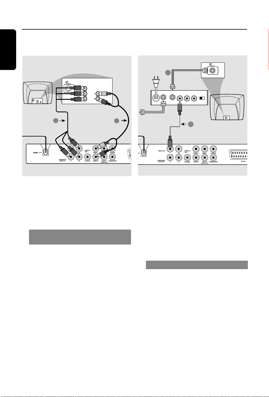
Using Component Video jacks
(Y Pb Pr)
1 Use the component video cables (red/
blue/green) to connect the DVD system’s
Y Pb Pr jacks to the corresponding
Component video input jacks (or labeled
as Y Pb Pr) on the TV (cable not supplied).
2 To hear the sound of this DVD Player
through your TV, use the audio cables
(white/red) to connect AUDIO OUT
[FRONT (L/R)] jacks of the DVD Player
to the corresponding AUDIO IN jacks on
the TV (cable not supplied).
3 Proceed to page 16 for detailed
Progressive Scan set up.
IMPORTANT!
– If your TV only has a single
Antenna In jack (or labeled as 75
ohm or RF In,) you will need an RF
modulator in order to view the DVD
playback on the TV. See your
electronics retailer or contact
Philips for details on RF modulator
availability and operations.
Using an accessory RF modulator
1 Use the composite video cable (yellow) to
connect the DVD Player’s VIDEO OUT
jack to the video input jack on the RF
modulator.
2 Use the RF coaxial cable (not supplied) to
connect the RF modulator to your TV’s
RF jack.
AUDIO IN
R L
VIDEO
IN
TO TVINT IN
CH3 CH4
2
1
RF coaxial cable to TV
Back of RF Modulator
(example only)
Antenna or
Cable TV signal
01-41 DVP5505S_EU_008 20/01/2005, 4:49 PM10
Loading ...
Loading ...
Loading ...