
User Manual of Thermal Smart Linkage Tracking System
0
Thermal Smart Linkage Tracking System
User Manual

User Manual of Thermal Smart Linkage Tracking System
i
© 2021 Hangzhou Hikvision Digital Technology Co., Ltd. All rights reserved.
About this Manual
The Manual includes instructions for using and managing the Product. Pictures, charts, images and all
other information hereinafter are for description and explanation only. The information contained in
the Manual is subject to change, without notice, due to firmware updates or other reasons. Please
find the latest version of this Manual at the Hikvision website (http://www.hikvision.com/).
Please use this Manual with the guidance and assistance of professionals trained in supporting the
Product.
Trademarks Acknowledgement
and other Hikvision’s trademarks and logos are the properties of Hikvision in various
jurisdictions.
Other trademarks and logos mentioned are the properties of their respective owners.
LEGAL DISCLAIMER
TO THE MAXIMUM EXTENT PERMITTED BY APPLICABLE LAW, THIS MANUAL AND THE PRODUCT
DESCRIBED, WITH ITS HARDWARE, SOFTWARE AND FIRMWARE, ARE PROVIDED “AS IS” AND “WITH ALL
FAULTS AND ERRORS”. HIKVISION MAKES NO WARRANTIES, EXPRESS OR IMPLIED, INCLUDING
WITHOUT LIMITATION, MERCHANTABILITY, SATISFACTORY QUALITY, OR FITNESS FOR A PARTICULAR
PURPOSE. THE USE OF THE PRODUCT BY YOU IS AT YOUR OWN RISK. IN NO EVENT WILL HIKVISION BE
LIABLE TO YOU FOR ANY SPECIAL, CONSEQUENTIAL, INCIDENTAL, OR INDIRECT DAMAGES, INCLUDING,
AMONG OTHERS, DAMAGES FOR LOSS OF BUSINESS PROFITS, BUSINESS INTERRUPTION, OR LOSS OF
DATA, CORRUPTION OF SYSTEMS, OR LOSS OF DOCUMENTATION, WHETHER BASED ON BREACH OF
CONTRACT, TORT (INCLUDING NEGLIGENCE), PRODUCT LIABILITY, OR OTHERWISE, IN CONNECTION
WITH THE USE OF THE PRODUCT, EVEN IF HIKVISION HAS BEEN ADVISED OF THE POSSIBILITY OF SUCH
DAMAGES OR LOSS.
YOU ACKNOWLEDGE THAT THE NATURE OF THE INTERNET PROVIDES FOR INHERENT SECURITY RISKS,
AND HIKVISION SHALL NOT TAKE ANY RESPONSIBILITIES FOR ABNORMAL OPERATION, PRIVACY
LEAKAGE OR OTHER DAMAGES RESULTING FROM CYBER-ATTACK, HACKER ATTACK, VIRUS INFECTION,
OR OTHER INTERNET SECURITY RISKS; HOWEVER, HIKVISION WILL PROVIDE TIMELY TECHNICAL
SUPPORT IF REQUIRED.
YOU AGREE TO USE THIS PRODUCT IN COMPLIANCE WITH ALL APPLICABLE LAWS, AND YOU ARE SOLELY
RESPONSIBLE FOR ENSURING THAT YOUR USE CONFORMS TO THE APPLICABLE LAW. ESPECIALLY, YOU
ARE RESPONSIBLE, FOR USING THIS PRODUCT IN A MANNER THAT DOES NOT INFRINGE ON THE RIGHTS
OF THIRD PARTIES, INCLUDING WITHOUT LIMITATION, RIGHTS OF PUBLICITY, INTELLECTUAL PROPERTY
RIGHTS, OR DATA PROTECTION AND OTHER PRIVACY RIGHTS. YOU SHALL NOT USE THIS PRODUCT FOR
ANY PROHIBITED END-USES, INCLUDING THE DEVELOPMENT OR PRODUCTION OF WEAPONS OF MASS
DESTRUCTION, THE DEVELOPMENT OR PRODUCTION OF CHEMICAL OR BIOLOGICAL WEAPONS, ANY
ACTIVITIES IN THE CONTEXT RELATED TO ANY NUCLEAR EXPLOSIVE OR UNSAFE NUCLEAR FUEL-CYCLE,
OR IN SUPPORT OF HUMAN RIGHTS ABUSES.
IN THE EVENT OF ANY CONFLICTS BETWEEN THIS MANUAL AND THE APPLICABLE LAW, THE LATER
PREVAILS.
User Manual of Thermal Smart Linkage Tracking System
ii
Regulatory Information
These clauses apply only to the products bearing the corresponding mark or information.
FCC Information
Please take attention that changes or modification not expressly approved by the party responsible for
compliance could void the user’s authority to operate the equipment.
FCC compliance: This equipment has been tested and found to comply with the limits for a Class A
digital device, pursuant to part 15 of the FCC Rules. These limits are designed to provide reasonable
protection against harmful interference when the equipment is operated in a commercial
environment. This equipment generates, uses, and can radiate radio frequency energy and, if not
installed and used in accordance with the instruction manual, may cause harmful interference to radio
communications. Operation of this equipment in a residential area is likely to cause harmful
interference in which case the user will be required to correct the interference at his own expense.
FCC Conditions
This device complies with part 15 of the FCC Rules. Operation is subject to the following two
conditions:
1. This device may not cause harmful interference.
2. This device must accept any interference received, including interference that may cause undesired
operation.
EU Conformity Statement
This product and - if applicable - the supplied accessories too are marked with "CE"
and comply therefore with the applicable harmonized European standards listed
under the Low Voltage Directive 2006/95/EC, the EMC Directive 2014/30/EU, the
RoHS Directive 2011/65/EU.
2012/19/EU (WEEE directive): Products marked with this symbol cannot be disposed
of as unsorted municipal waste in the European Union. For proper recycling, return
this product to your local supplier upon the purchase of equivalent new equipment,
or dispose of it at designated collection points. For more information see:
www.recyclethis.info.
2006/66/EC (battery directive): This product contains a battery that cannot be
disposed of as unsorted municipal waste in the European Union. See the product
documentation for specific battery information. The battery is marked with this
symbol, which may include lettering to indicate cadmium (Cd), lead (Pb), or mercury
(Hg). For proper recycling, return the battery to your supplier or to a designated collection point. For
more information see: www.recyclethis.info.
Industry Canada ICES-003 Compliance
This device meets the CAN ICES-3 (A)/NMB-3(A) standards requirements.
이 기기는 업무용 환경에서 사용할 목적으로 적합성평가를 받은 기기로서 가정용 환경에서
사용하는 경우 전파간섭의 우려가 있습니다.

User Manual of Thermal Smart Linkage Tracking System
iii
Symbol Convention
The symbols that may be found in this document are defined as follows.
Symbol
Description
Provides additional information to emphasize or supplement
important points of the main text.
Indicates a potentially hazardous situation, which if not avoided,
could result in equipment damage, data loss, performance
degradation, or unexpected results.
Indicates a hazard with a high level of risk, which if not avoided, will
result in death or serious injury.
Safety Instruction
These instructions are intended to ensure that user can use the product correctly to avoid danger or
property loss.
Laws and Regulations
● The lightning protection and grounding design of outdoor installation and wiring should be in
compliance with the lightning protection requirements of the buildings and local laws and
regulations.
● Use of the product must be in strict compliance with the local electrical safety regulations.
Storage
● Store the device in dry, well-ventilated, corrosive-gas-free, no direct sunlight, and no heating
source environment. Neglect may cause fire hazard.
● To avoid heat accumulation, good ventilation is required for a proper operating environment.
● DO NOT touch the heat dissipation component to avoid burns.
Transportation
● Keep the device in original or similar packaging while transporting it.
● Keep all wrappers after unpacking them for future use. In case of any failure occurred, you need
to return the device to the factory with the original wrapper. Transportation without the original
wrapper may result in damage on the device and the company shall not take any responsibilities.
● DO NOT drop the product or subject it to physical shock. Keep the device away from magnetic
interference.
Installation
● When the device is mounted on wall or ceiling, the device shall be firmly fixed.
● Avoid equipment installation on vibratory surface or places subject to shock (neglect may cause
equipment damage).
Power Supply
● Make sure that the power has been disconnected before you wire, install, or disassemble the
device.
● The input voltage should conform to IEC60950-1 standard: SELV (Safety Extra Low Voltage) and
the Limited Power Source. Refer to the appropriate documentation for detailed information. The
standard power supply is 12 VDC, or 24 VAC, please make sure your power supply matches with
your camera.

User Manual of Thermal Smart Linkage Tracking System
iv
● Use the power adapter provided by qualified manufacturer. Refer to the product specification for
detailed power requirements. It is recommended to provide independent power adapter for
each device as adapter overload may cause over-heating or a fire hazard.
Battery
● DO NOT place the battery near heating or fire source. Avoid direct sunlight.
● Improper use or replacement of the battery may result in explosion hazard. Replace with the
same or equivalent type only. Dispose of used batteries according to the instructions provided by
the battery manufacturer.
● For long-term storage of the battery, make sure it is fully charged every half year to ensure the
battery quality. Otherwise, damage may occur.
System Security
● You acknowledge that the nature of Internet provides for inherent security risks, and our
company shall not take any responsibilities for abnormal operation, privacy leakage or other
damages resulting from cyber attack, hacker attack, however, our company will provide timely
technical support if required.
● Please enforce the protection for the personal information and the data security as the device
may be confronted with the network security problems when it is connected to the Internet.
Please contact us when the device might exist network security risks.
● Please understand that you have the responsibility to configure all the passwords and other
security settings about the device, and keep your user name and password.
Maintenance
● Clean the lens with soft and dry cloth or wiping paper to avoid scratching it.
● If the product does not work properly, please contact your dealer or the nearest service center.
We shall not assume any responsibility for problems caused by unauthorized repair or
maintenance.
● A few device components (e.g., electrolytic capacitor) require regular replacement. The average
lifespan varies, so periodic checking is recommended. Contact your dealer for details.
Using Environment
● DO NOT expose the device to extremely hot, cold, dusty, corrosive, saline-alkali, or damp
environments. Make sure the running environment meets the requirement of the device.
● DO NOT aim the lens at the sun or any other bright light.
● Keep the camera away from liquid while in use.
Emergency
● If smoke, odor, or noise arises from the device, immediately turn off the power, unplug the
power cable, and contact the service center.
COMPLIANCE NOTICE: The thermal series products might be subject to export controls in various countries or
regions, including without limitation, the United States, European Union, United Kingdom and/or other member
countries of the Wassenaar Arrangement. Please consult your professional legal or compliance expert or local
government authorities for any necessary export license requirements if you intend to transfer, export, re-export
the thermal series products between different countries.

User Manual of Thermal Smart Linkage Tracking System
v
Table of Contents
Chapter 1 Overview ...................................................................................................................... 1
1.1 Overview ...................................................................................................................................................... 1
1.2 System Requirement .................................................................................................................................... 1
1.3 Function ....................................................................................................................................................... 1
Chapter 2 Appearance Description ................................................................................................ 4
2.1 Type I Smart Linkage System Appearance .................................................................................................... 4
2.2 Type II Smart Linkage System Appearance ................................................................................................... 5
2.3 Cable Wiring................................................................................................................................................. 6
2.3.1 Speed Dome Cables .............................................................................................................................. 6
2.3.2 Bullet Camera Cables ............................................................................................................................ 6
Chapter 3 Installation.................................................................................................................... 7
3.1 Pre-Installation ............................................................................................................................................. 7
3.1.1 Wide Range Coverage ........................................................................................................................... 7
3.1.2 Memory Card Installation ..................................................................................................................... 8
3.2 Bracket Installation .................................................................................................................................... 10
3.2.1 Wall Mounting .................................................................................................................................... 10
3.2.2 Horizontal pole mounting ................................................................................................................... 11
3.3 Smart Linkage Tracking System Installation ............................................................................................... 12
3.3.1 Install Device with Wall Mount Bracket .............................................................................................. 12
3.3.2 Install Device with Pole Mount Bracket .............................................................................................. 15
3.4 Angle Adjustment ...................................................................................................................................... 19
3.5.1 Install Network Cable Waterproof Jacket ............................................................................................ 20
3.5.2 Waterproof Other Cables .................................................................................................................... 20
Chapter 4 Network Connection ................................................................................................... 22
4.1 Set the Camera over the LAN ..................................................................................................................... 22
4.1.1 Wire over the LAN ............................................................................................................................... 22
4.1.2 Activate the System ............................................................................................................................ 23
4.2 Set the Network Camera over the WAN .................................................................................................... 27
4.2.1 Static IP Connection ............................................................................................................................ 27
4.2.2 Dynamic IP Connection ....................................................................................................................... 28
Chapter 5 System Settings ........................................................................................................... 31
5.1 Access to the System.................................................................................................................................. 31
5.1.1 Add Devices ........................................................................................................................................ 31
5.1.2 Live View ............................................................................................................................................. 32
Chapter 6 Remote Configuration ................................................................................................. 33
6.1 Login the Speed Dome ............................................................................................................................... 33
6.2 Calibration .................................................................................................................................................. 35
6.2.1 Set Manual Calibration........................................................................................................................ 35
6.2.2 Set Auto Calibration ............................................................................................................................ 37
6.3 Calibration Veryfication ............................................................................................................................. 37
6.4 Set Tracking Parameters ............................................................................................................................. 38
6.5 VCA Rule Configuration .............................................................................................................................. 39
Chapter 7 Auto Smart Linkage Tracking ....................................................................................... 43
Appendix ......................................................................................................................................... 44
Frequently Asked Questions (FAQ) ....................................................................................................................... 44
Device Running Error ........................................................................................................................................ 44
Device Upgrading .............................................................................................................................................. 44
Others ............................................................................................................................................................... 44
Common Material Emissivity Reference ............................................................................................................... 45

User Manual of Thermal Smart Linkage Tracking System
1
Chapter 1 Overview
1.1 Overview
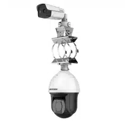
The Thermal Smart Linkage Tracking Systems is formed by one fixed camera and one
PTZ camera. The PTZ camera smartly tracks multiple moving targets, and the fixed
camera offers the panoramic view. The linkage of both can be realized by the client
software.
It provides you with smart detection of moving targets, and multiple targets can be
tracked simultaneously.
The system mainly applies to major industrial infrastructures requiring perimeter
prevention, such as: airport, prison, railway, museum, enterprise, high-end villas and
others.
1.2 System Requirement
System requirement of web browser accessing is as follows:
Operating System: Microsoft Windows XP SP1 and above version / Vista / Win7 /
Server 2003 / Server 2008 32bits
CPU: Intel Pentium IV 3.0 GHz or higher
RAM: 1G or higher
Display: 1024×768 resolution or higher
Web Browser: Internet Explorer 8.0 and above version, Apple Safari 5.02 and above
version, Mozilla Firefox 5 and above version and Google Chrome 18 and above
versions.
1.3 Function
The functions vary depending on the models of speed dome.
Thermal View
The system provides thermal view with the uncooled focal plane arrays.
PTZ Limits
The speed dome can be programmed to move within the PTZ limits (left/right,
up/down).
Scan Modes
The speed dome provides 5 scan modes: auto scan, tilt scan, frame scan, random
scan and panorama scan.
Presets
A preset is a predefined image position. When the preset is called, the speed dome
will automatically move to the defined position. The presets can be added, modified,
deleted and called.

User Manual of Thermal Smart Linkage Tracking System
2
Label Display
The on-screen label of the preset title, azimuth/elevation, zoom, time and speed
dome name can be displayed on the monitor. The displays of time and speed dome
name can be programmed.
Auto Flips
In manual tracking mode, when a target object goes directly beneath the speed
dome, the video will automatically flips 180 degrees in horizontal direction to
maintain continuity of tracking. This function can also be realized by auto mirror
image depending on different camera models.
Privacy Mask
This function allows you to block or mask certain area of a scene, for preventing the
personal privacy from recording or live viewing. A masked area will move with pan
and tilt functions and automatically adjust in size as the lens zooms telephoto and
wide.
3D Positioning
In the client software, use the left key of mouse to click on the desired position in the
video image and drag a rectangle area in the lower right direction, then the speed
dome will move the position to the center and allow the rectangle area to zoom in.
Use the left key of mouse to drag a rectangle area in the upper left direction to move
the position to the center and allow the rectangle area to zoom out.
Proportional Pan/Tilt
Proportional pan/tilt automatically reduces or increases the pan and tilt speeds
according to the amount of zoom. At telephoto zoom settings, the pan and tilt
speeds will be slower than at wide zoom settings. This keeps the image from moving
too fast on the live view image when there is a large amount of zoom.
Auto Focus
The auto focus enables the camera to focus automatically to maintain clear video
images.
Day/Night Auto Switch
The speed domes deliver color images during the day. And as light diminishes at
night, the speed domes switch to night mode and deliver black and white images
with high quality.
Slow Shutter
In slow shutter mode, the shutter speed will automatically slow down in low
illumination conditions to maintain clear video images by extending the exposure
time. The feature can be enabled or disabled.
Backlight Compensation (BLC)
If you focus on an object against strong backlight, the object will be too dark to be
seen clearly. The BLC (Backlight Compensation) function can compensate light to the
object in the front to make it clear, but this causes the over-exposure of the
background where the light is strong.
Wide Dynamic Range (WDR)
The wide dynamic range (WDR) function helps the camera provide clear images even
under back light circumstances. When there are both very bright and very dark areas
simultaneously in the field of view, WDR balances the brightness level of the whole
image and provide clear images with details.
White Balance (WB)
White balance can remove the unrealistic color casts. White balance is the white
rendition function of the camera to adjust the color temperature according to the
environment automatically.
Patrol
A patrol is a memorized series of pre-defined preset function. The scanning speed
between two presets and the dwell time at the preset are programmable.
Pattern
A pattern is a memorized series of pan, tilt, zoom, and preset functions. By default
the focus and iris are in auto status during the pattern is being memorized.

User Manual of Thermal Smart Linkage Tracking System
3
Power Off Memory
The speed dome supports the power off memory capability with the predefined
resume time. It allows the speed dome to resume its previous position after power is
restored.
Scheduled Task
A scheduled task is a preconfigured action that can be performed automatically at a
specific date and time. The programmable actions include: auto scan, random scan,
patrol 1-8 ,pattern 1-4, preset 1-8,frame scan, panorama scan, tilt scan, day, night,
reboot, PT adjust, Aux Output, etc.
Park Action
This feature allows the speed dome to start a predefined action automatically after a
period of inactivity.
3D Digital Noise Reduction
Comparing with the general 2D digital noise reduction, the 3D digital noise reduction
function processes the noise between two frames besides processing the noise in
one frame. The noise will be much less and the video will be clearer.
User Manual of Thermal Smart Linkage Tracking System
4
Chapter 2 Appearance Description
There are two kinds of Thermal and Optical Smart Linkage Tracking Systems: Type I
speed dome, and Type II speed dome. The appearance descriptions are shown
below.
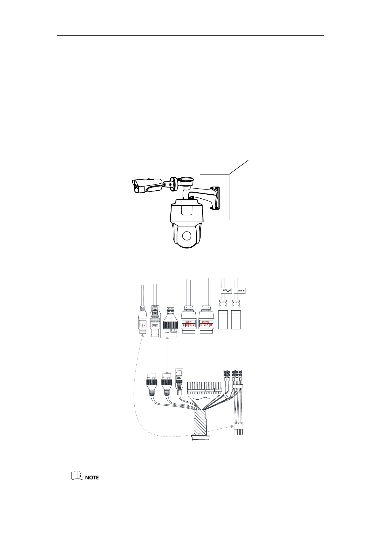
2.1 Type I Smart Linkage System Appearance
Refer to the following figures for Type I Smart Linkage Tracking Systems overview.
Figure 2-1 Type I Thermal Smart Linkage Tracking System Overview
Network
Interface
Video
Interface
Alarm In/Out
Audio In/Out
RS-485
Audio In/Out
Alarm In/Out
Power
Cable
Video
Interface
Network
Interface
Power
Outlet
Figure 2-2 Type I Thermal Smart Linkage Tracking System Cables

User Manual of Thermal Smart Linkage Tracking System
5
Refer to 2.3 Cable for cable wirings.
2.2 Type II Smart Linkage System Appearance
Refer to the following figures for Type II Smart Linkage Tracking Systems overview.
CVBS
Figure 2-3 Type II Thermal Smart Linkage Tracking System Overview
Network
Interface
Video
Interface
Alarm In/Out
Audio In/Out
RS-485
Audio In/Out
Alarm In/Out
Power
Cable
Video
Interface
Network
Interface
Power
Outlet
Figure 2-4 Type II Thermal Smart Linkage Tracking System Cables
Refer to 2.3 Cable for cable wirings.

User Manual of Thermal Smart Linkage Tracking System
6
2.3 Cable Wiring
2.3.1 Speed Dome Cables
1. The speed dome has two network interfaces:
Connect one network cable to the external internet, and connect the other
network cable to the bullet camera network interface.
2. The speed dome has two power interfaces:
Connect one power cable to the external power source, and connect the other
power cable to the bullet camera power interface.
2.3.2 Bullet Camera Cables
1. The bullet camera has two power types:
For bullet camera, both 24 V AC and 12 V DC are supported. To use 12V DC
power supply, you MUST connect the positive/negative terminals correctly.
For the Smart Linkage tracking system, connect the bullet camera power cable to
the speed dome power output.
2. The speed dome has two power interfaces:
Connect one power cable to the external power source, and connect the other
power cable to the bullet camera power interface.

User Manual of Thermal Smart Linkage Tracking System
7
Chapter 3 Installation
3.1 Pre-Installation
● Make sure the device in the package is in good condition and all the assembly
parts are included.
● The standard power supply is 24V AC, please make sure your power supply
matches your camera.
● Make sure all the related equipment is power-off during the installation.
● Check the specification for the installation environment.
● Make sure that the wall is strong enough to withstand eight times the weight
of the camera and the bracket.
For the camera that supports IR, mind the following precautions to prevent IR
reflection:
● Do NOT remove the protective film until you finish the installation. For any
dust or grease on the cover, clean them with clean soft cloth and isopropyl
alcohol.
● Make sure that there is no reflective surface too close to the camera lens. The
IR light from the camera may reflect back into the lens causing reflection.
● Do NOT drag the camera with its waterproof cables, or the waterproof
performance is affected.
DO NOT lift the
camera by
lifting the cables
Figure 3-1 Do NOT Lift by Cables
3.1.1 Wide Range Coverage
For fixed lens camera, the auto-focus function, and remote manual focus function are
not supported.
Select the proper installation site, and proper lens focal length according to the Wide
Range Coverage list below:

User Manual of Thermal Smart Linkage Tracking System
8
Lens (focal length)
7mm
10mm
15mm
25mm
35mm
50mm
75mm
Detection range (Vehicles)
631m
902m
1353m
2255m
3157m
4510m
6765m
Detection range (Humans)
206m
294m
441m
735m
1029m
1471m
2206m
Recognition range (Vehicles)
158m
225m
338m
564m
789m
1127m
1691m
Recognition range (Humans)
51m
74m
110m
184m
257m
368m
551m
Identification range (Vehicles)
79m
113m
169m
282m
395m
564m
846m
Identification range (Humans)
26m
37m
55m
92m
129m
184m
276m
This table is for reference only, and the actual detection range may vary according
to different camera settings, mounting condition, monitor and so on.
3.1.2 Memory Card Installation
Before you start:
Install microSD card to the bullet camera, and install microSD card to the speed
dome. To ensure the air impermeability, seal the memory card slot following the
same procedure you opened it.
Purpose:
Install the memory card into the camera, and you can save the recordings and
snapshots in the card. If you do not need saving videos in the memory card, skip this
step.
Bullet Camera Memory Card Installation
Steps:
1. Use the screw driver to open the memory card slot beneath the device.
Figure 3-2 Open the Memory Card Slot
2. Insert the microSD card into the memory card slot and make sure the chip faces
toward the lens. When it clicks, the card is properly installed.

User Manual of Thermal Smart Linkage Tracking System
9
Figure 3-3 Insert the MicroSD Card
3. Use the screwdriver to cover the microSD card slot.
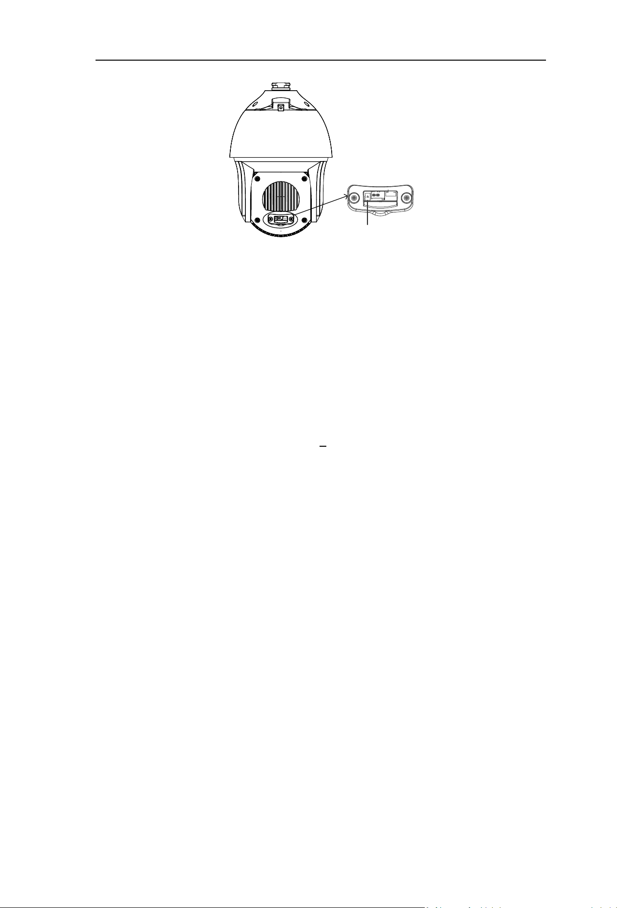
Speed Dome Memory Card Installation
Steps:
1. Remove the protective sticker.
Figure 3-4 Open the Memory Card Slot
2. Use the screw driver to remove the memory card slot cover on the back of the
speed dome.
Memory Card
Slot Cover
Figure 3-5 Memory Card Slot
3. Insert the MicroSD card into the memory card slot and make sure the chip faces
toward the lens. When it clicks, the card is properly installed.
User Manual of Thermal Smart Linkage Tracking System
10
MicroSD Card
Figure 3-6 Insert the MicroSD Card
4. Use the screwdriver to cover the memory card slot.
3.2 Bracket Installation
The speed dome can be installed to a thread interface or non-thread interface
bracket. The non-thread bracket is highly recommended.
When you select a thread bracket, please install the pendent adapter (supplied)
between the bracket and speed dome. Any mismatch problems shall be taken
responsibility by the user.
The dimension of pendant adapter is G1
1
2
.
For cement wall, you need to use the expansion screw to fix the bracket.
For wooden wall, you can just use the self-tapping screw to fix the bracket.
Please make sure that the wall is strong enough to withstand at least 8 times the
weight of the dome and the bracket.
The wall must be thick enough to mount the expansion screws.
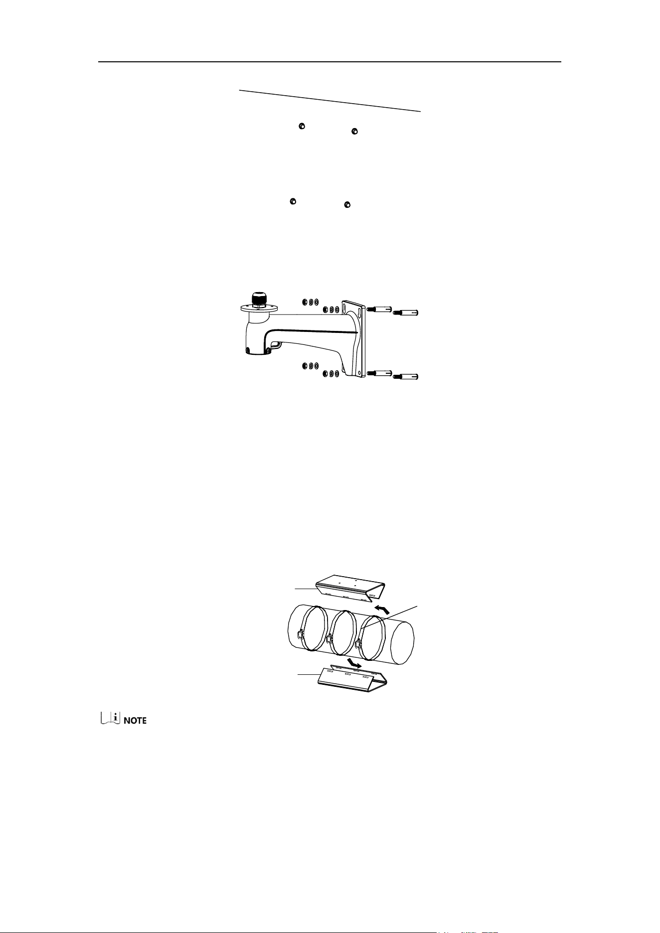
3.2.1 Wall Mounting
Steps:
1. Get the bracket and screws from the packing box.
2. Drill 4 φ12 screw holes in the wall according to the screw hole sites of the bracket,
and then insert M8 expansion screws into the screw holes.
User Manual of Thermal Smart Linkage Tracking System
11
Figure 3-7 Drill Screw Hole and Insert Expansion Screw
3. Route the cables through the internal part of the bracket and then secure the
bracket with 4 hex nuts and washers.
Figure 3-8 Drill Screw Holes
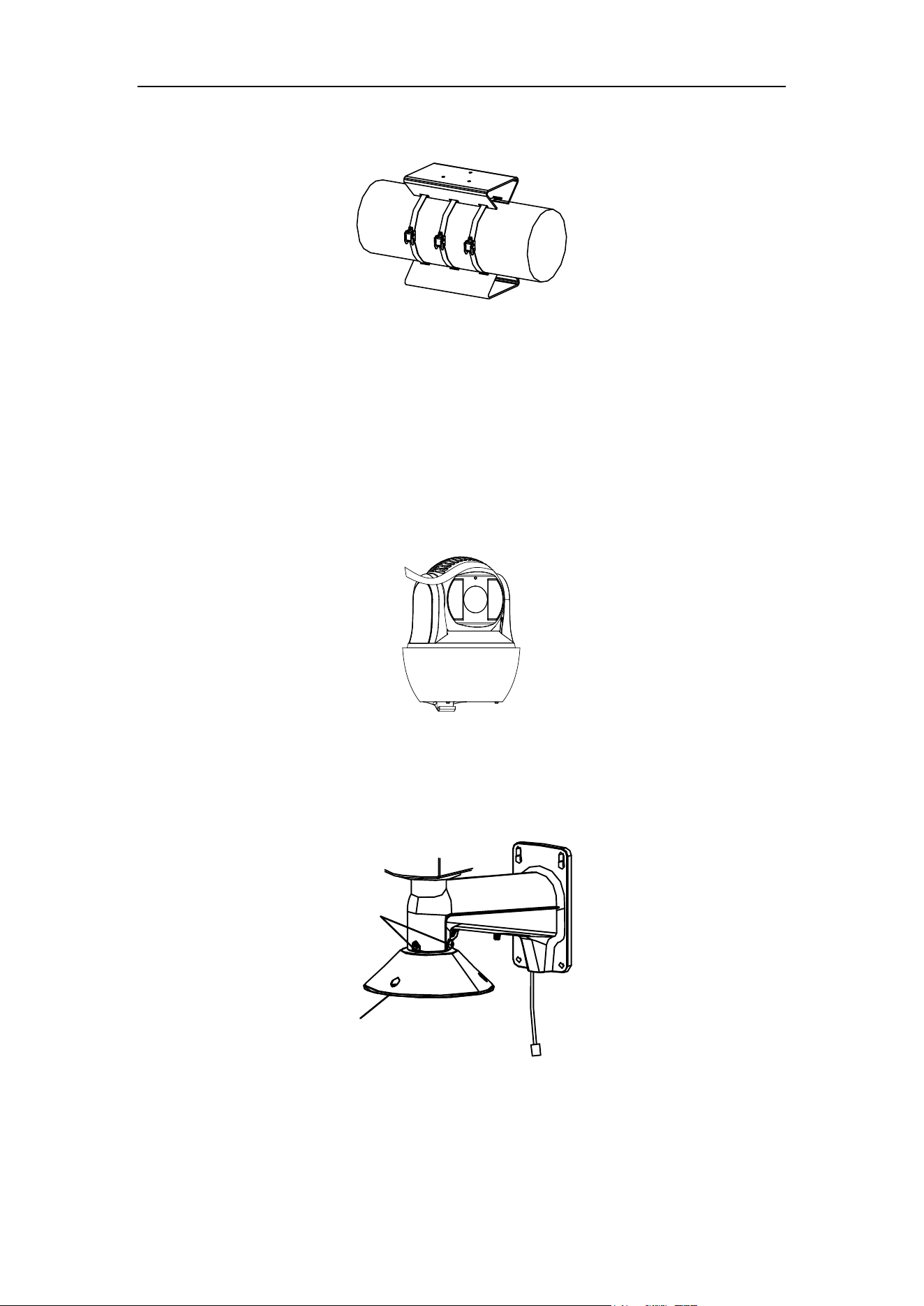
3.2.2 Horizontal pole mounting
Steps:
1. Get the bracket and accessories from the packing box.
2. Install the loop onto the pole.
1) Fix the loop with the pole loosely.
2) Route the loop rings into the holes of the fixing plates to fix the fixing plates
onto the loop.
Loop
Upper Fixing Plate
Bottom Fixing Plate
Figure 3-9 Install the Loop to the Pole
The upper fixing plate has three screw holes on the surface, and is used for fixing
the bullet camera or box camera.
The bottom fixing plate has four screw holes on the surface, and is used for fixing
the speed dome.
Make sure that the upper fixing plate is on the right top of the pole and the
bottom fixing plate is on the right bottom of the pole.
User Manual of Thermal Smart Linkage Tracking System
12
3) Adjust the fixing plate to the right position and then tighten the loop rings to
secure the fixing plates.
Figure 3-10 Adjust Fixing Plate Position
3.3 Smart Linkage Tracking System Installation
3.3.1 Install Device with Wall Mount Bracket
Steps:
1. Remove the protective sticker.
Figure 3-11 Remove Protective Sticker
2. Install the speed dome head cover.
1) Loosen the two lock screws with the Allen wrench. Make sure the screws do
not appear in bracket inner side.
Lock Screw
Head Cover
Figure 3-12 Loosen the lock screws
2) Install the head cover to the bottom of the bracket.
3) Fix the head cover with the bracket according to the figure below.

User Manual of Thermal Smart Linkage Tracking System
13
①
②
③
Figure 3-13 Installing the Head Cover
4) Fix two lock screws with the Allen wrench to secure the camera.
3. Hook the one end of safety rope to the back box of speed dome, and the other
end of safety rope to the bracket.
Figure 3-14 Hook the Safety Rope
4. Fix the speed dome with head cover.
1) Route the cables through the head cover and water-proof connector.
Water-proof
Connector
Figure 3-15 Route the cables

User Manual of Thermal Smart Linkage Tracking System
14
2) Tighten the screws between the speed dome and the head cover with the Allen
wrench to secure the speed dome onto the bracket.
Figure 3-16 Fix the Speed Dome with Head Cover
5. Install the junction box.
1) Unscrew the screw of top cover with the cross screwdriver, then open the
cover.
Top
Cover
Figure 3-17 Open the Top Cover of Junction Box
2) Route the cables through the bottom hole of junction box.
3) Fix the junction box onto the bracket with three M6×14 screws.
Figure 3-18 Junction Box Installation
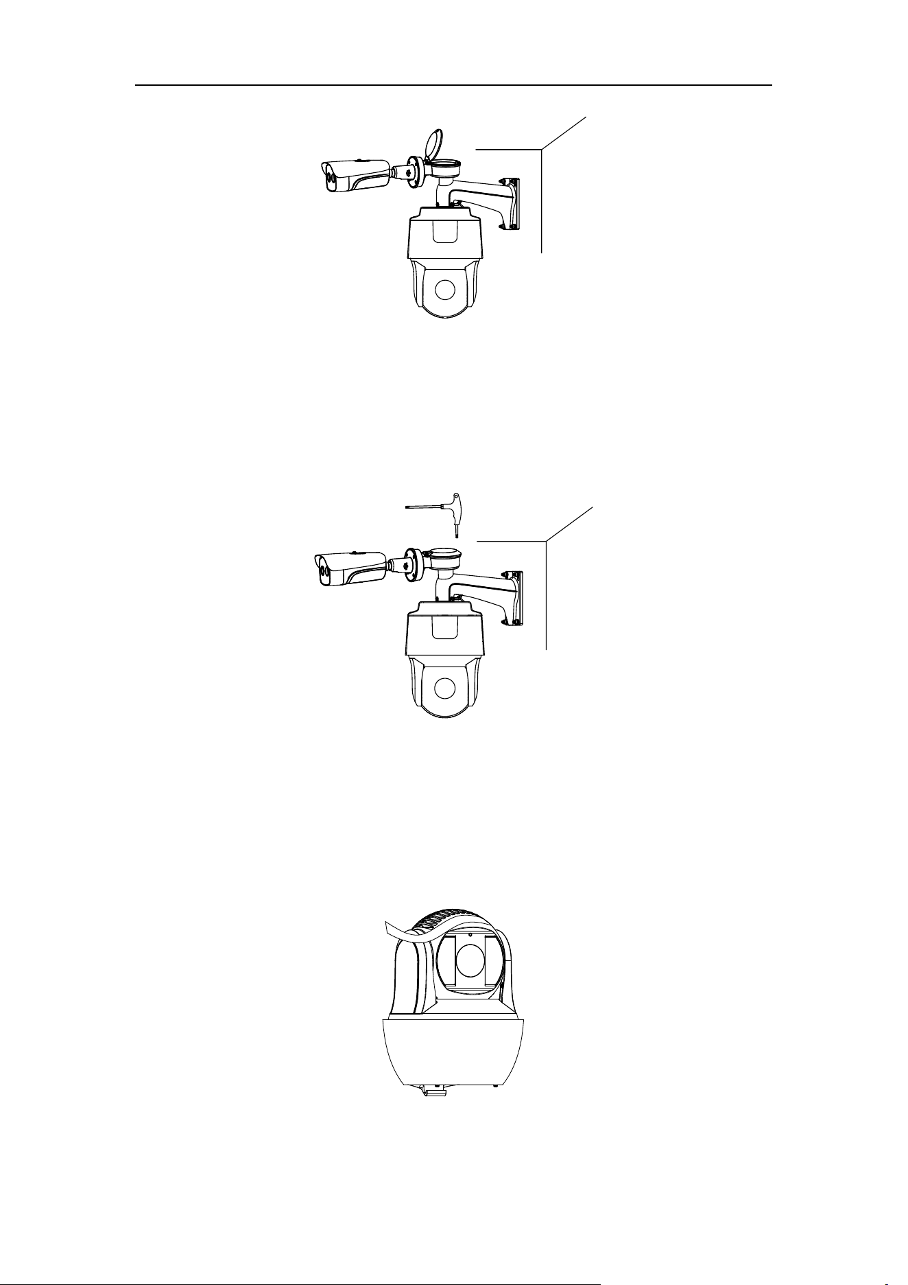
6. Route the cables of bullet camera through the left hole of junction box.
7. Fix the bullet camera with four M5 screws.
User Manual of Thermal Smart Linkage Tracking System
15
Figure 3-19 Bullet Camera Installation
8. Connect the cables, and then place the cables into the junction box. Refer to the
Chapter 2 Appearance Description.
9. Close the top cover, then tight the screw of cover with cross screwdriver.
Figure 3-20 Finish Installation
10. Remove the protective film of the IR lens after you finish installing
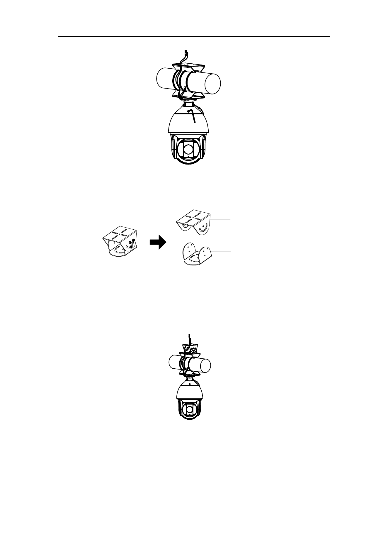
3.3.2 Install Device with Pole Mount Bracket
1. Remove the protective sticker.
Figure 3-21 Remove Protective Sticker
2. Install the head bracket to the loop bracket.

User Manual of Thermal Smart Linkage Tracking System
16
Figure 3-22 Head Bracket Installation
3. Install the speed dome head cover.
1) Loosen the two lock screws with the Allen wrench. Make sure the screws do not
appear in bracket inner side.
2) Install the head cover to the bottom of the bracket.
3) Fix the head cover with the bracket according to the figure below.
①
②
Figure 3-23 Installing Speed Dome Head Cover
4) Fix two lock screws with the Allen wrench to secure the camera.
4. Hook the one end of safety rope to the back box of speed dome, and the other
end of safety rope to the bracket.
User Manual of Thermal Smart Linkage Tracking System
17
Figure 3-24 Hook the Safety Rope
5. Fix the speed dome with head cover.
1) Refer to Chapter 2 to connect the power cable and network cable.
2) Hook the speed dome onto the head cover.
Figure 3-25 Fix the Speed Dome with Head Cover
3) Use the Allen wrench to tighten the screws and secure the speed dome onto
the head cover.
User Manual of Thermal Smart Linkage Tracking System
18
Figure 3-26 Tighten the Screws
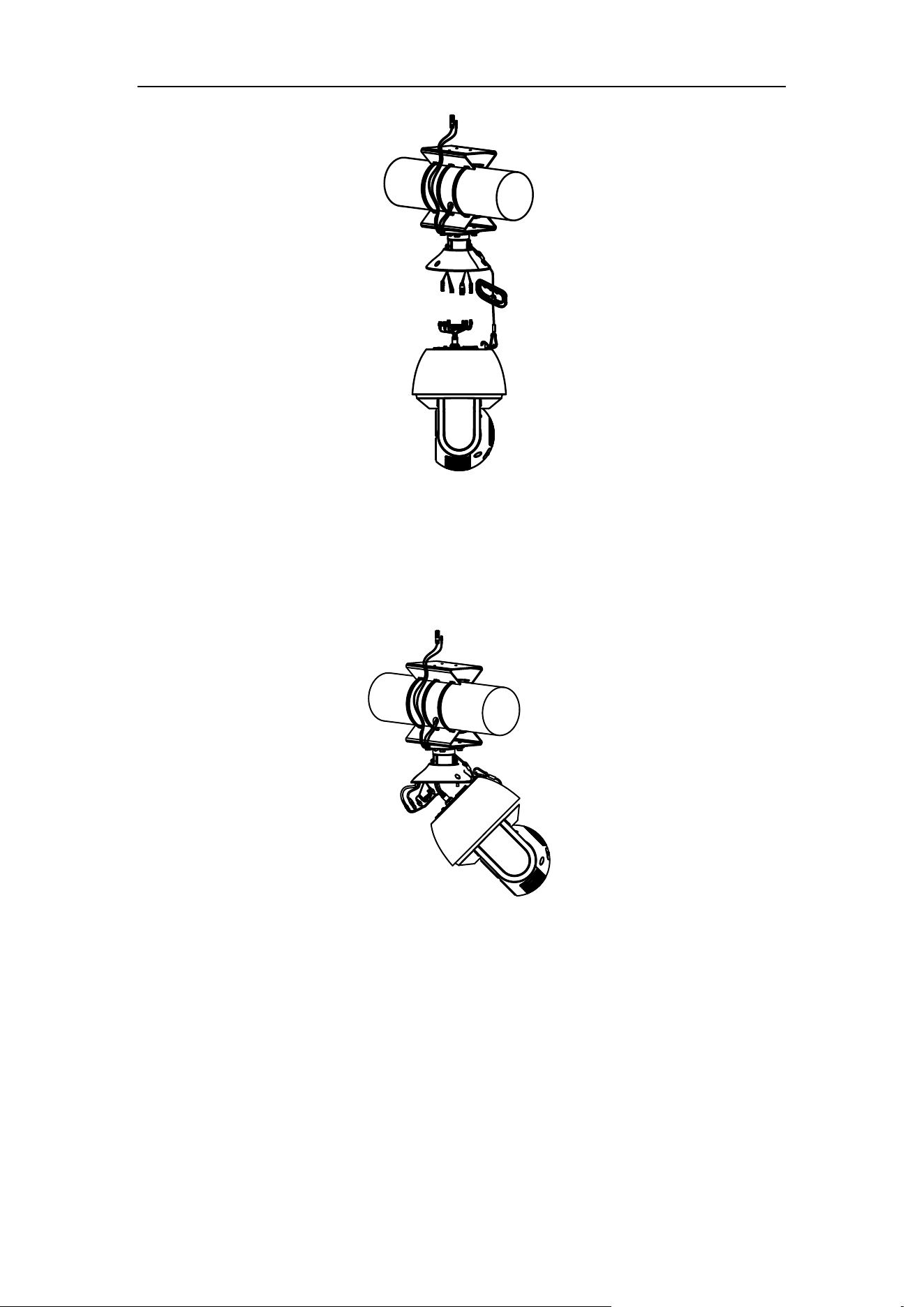
6. Install the PT joint
1) Disassemble the PT joint.
PT Joint Top
PT Joint Bottom
Figure 3-27 Disassemble the PT Joint
2) Route the cables from the bracket through the PT joint bottom.
3) Adjust the pan direction of the PT bottom (range: - 45° to + 45°).
4) Fix the PT joint bottom to the bracket with the M6 × 12 screws.
Figure 3-28 Bracket Installation
7. Install the junction box.
1) Route the cables through the bottom hole of junction box.
2) Align the PT joint screw holes with the junction box screw holes. Make sure the
TOP on the junction box points to the installation wall.

User Manual of Thermal Smart Linkage Tracking System
19
Figure 3-29 Junction Box Installation
3) Fix the junction box onto the PT joint with four M4×16 stainless steel screws.
CVBS
Figure 3-30 Bullet Camera Installation
8. Remove the protective film of the IR lens after you finish installing.
3.4 Angle Adjustment
Steps:
1. Loosen the screw to adjust the tilting position [0° to 90°]. Tighten the screw.
2. Loosen the screw to adjust the rotation position [0° to 360°]. Tighten the screw.
Screw
User Manual of Thermal Smart Linkage Tracking System
20
Figure 3-31 2-axis Adjustment
3.5 Waterproof Measures (Optional)
Purpose:
If the camera is installed outdoor, you should use the waterproof accessory or tapes
to waterproof the cables. Otherwise the cables might get wet or a short circuit might
occur.
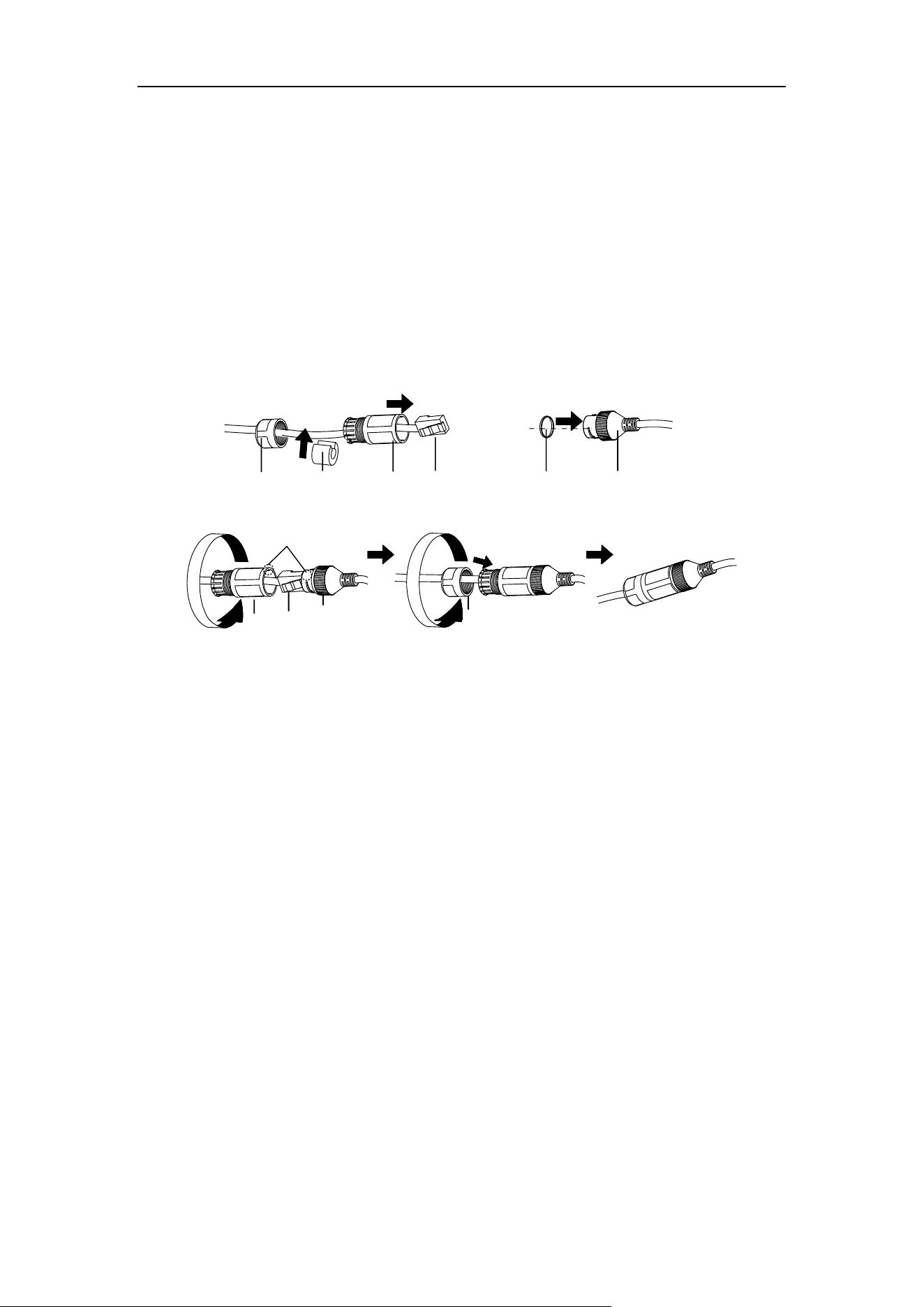
3.5.1 Install Network Cable Waterproof Jacket
⑥
④
②
③
①
④
⑤
⑥
③
①
Align
Figure 3-32 Install Waterproof Jacket
Steps:
1. Feed the network cable through ① and ③ in order.
2. Fix ② on the network cable between ① and ③.
3. Place ⑤ onto the end of ⑥, and plug the RJ45 male connector into RJ45
female connector.
4. Screw ③ to ⑥ clockwise.
5. Push ② into ③.
6. Secure ① with the ③ in clockwise direction.
3.5.2 Waterproof Other Cables
After routing and connecting the cables, use the waterproof tapes to wrap up the
cables. Connected cables and spare cables both should be wrapped up as the figures
below.

User Manual of Thermal Smart Linkage Tracking System
21
Figure 3-33 Waterproof Cables

User Manual of Thermal Smart Linkage Tracking System
22
Chapter 4 Network Connection
Before you start:
If you want to set the network speed dome via a LAN (Local Area Network), please
refer to Section 4.1.
If you want to set the network speed dome via a WAN (Wide Area Network),
please refer to Section 4.2.
4.1 Set the Camera over the LAN
Purpose:
To view and configure the camera via a LAN, you need to connect the network
camera in the same subnet with your computer, and install the SADP or client
software to search and change the IP of the network camera.
For the detailed introduction of SADP, please refer to Appendix.
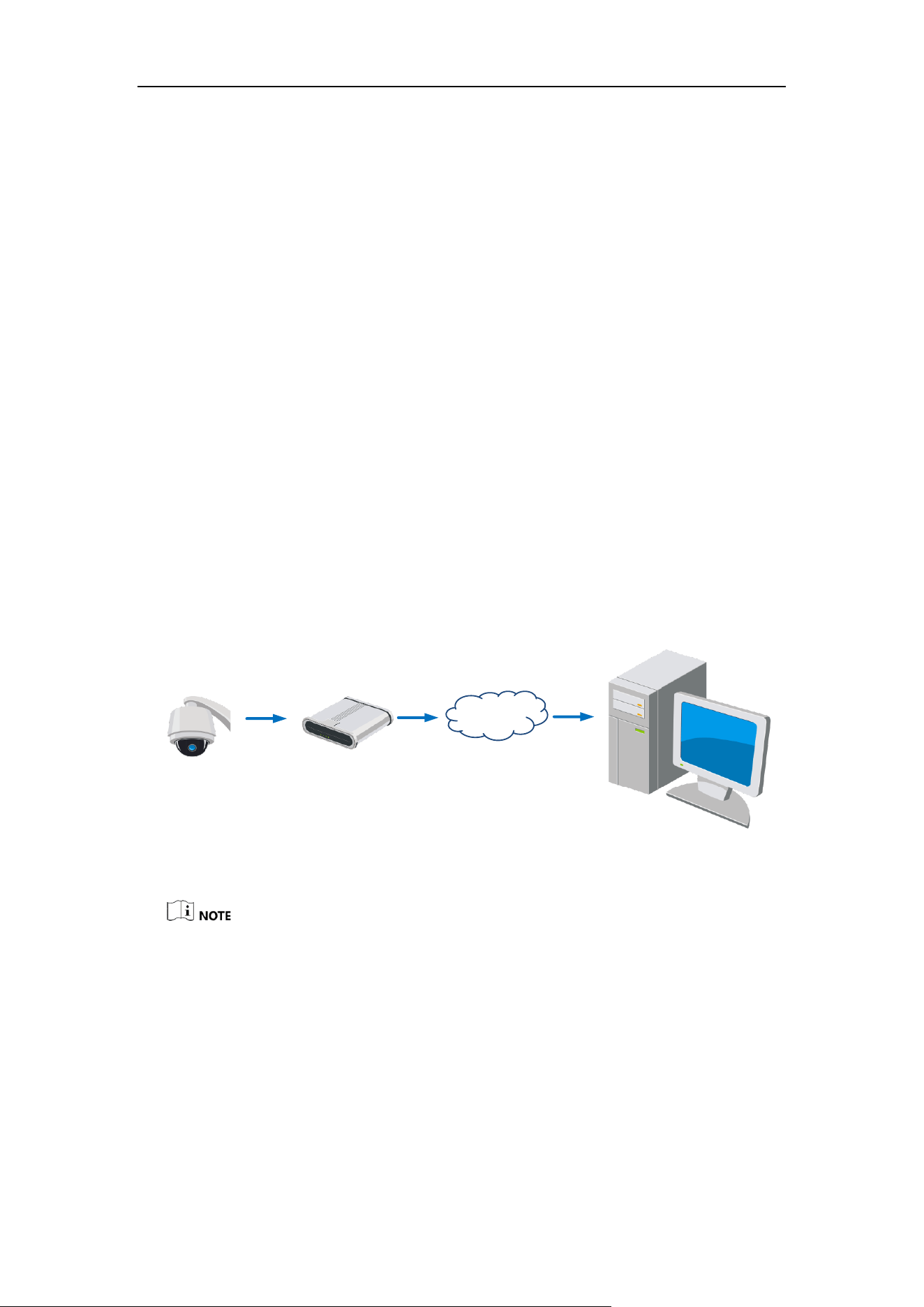
4.1.1 Wire over the LAN
The following figures show the two ways of cable connection of a network camera
and a computer:
Purpose:
After completing the installation of Smart Linkage tracking system, you need to
set the function configurations and related parameters. Make sure that the system
is properly connected with your PC. Two methods are available for the system
connection, as shown in Figure 4-1.
The following figure shows the cable connection of network speed dome.
Client Software
Client Software
Network Cable
(Straight-Through
Wired Cables)
Network Cable
(Crossover Wired
Cables)
Figure 4-1 Connecting Directly

User Manual of Thermal Smart Linkage Tracking System
23
4.1.2 Activate the System
Purpose:
You are required to activate the devices first before you can use the system.
Activation via iVMS-4200
Steps:
1. Install the client software. You can view the live video and operate the device with
the client software.
2. Follow the installation prompts to install the client software and WinPcap. The
configuration interface and live view interface of client software are shown below.
Figure 4-2 iVMS-4200 Control Panel
3. Enter Control Panel -> Maintenance and Management ->Device Management.
4. Click server tab to enter the server management interface. The online devices list
is shown in Figure 4-3.

User Manual of Thermal Smart Linkage Tracking System
24
Figure 4-3 Device List
5. Select the device and click Activate to enter the activation interface, as shown in
Figure 4-4.
Figure 4-4 Activation Interface
6. Create a password and input the password in the password field, and confirm the
password.
STRONG PASSWORD RECOMMENDED– We highly recommend you create a
strong password of your own choosing (Using a minimum of 8 characters,
including at least three of the following categories: upper case letters, lower
case letters, numbers, and special characters.) in order to increase the security
of your product. And we recommend you reset your password regularly,
especially in the high security system, resetting the password monthly or
weekly can better protect your product.
7. Click OK to save the password.
8. You can check whether the activation is completed on the popup window. If
activation failed, please make sure that the password meets the requirement and
then try again.
If you use third party VMS software, please contact technical support of our
branch for camera firmware.

User Manual of Thermal Smart Linkage Tracking System
25
For detailed information about client software of our company, please refer to
the user manual of the software. This manual mainly introduces accessing to the
network speed dome by web browser.
Activation via Web Browser
Steps:
1. Power on the speed dome, and connect the speed dome to the network.
2. Input the IP address into the address bar of the web browser, and click Enter to
enter the activation interface.
The default IP address of the speed dome is 192.168.1.64.
Figure 4-5 Activation Interface(Web)
3. Create a password and input the password into the password field.
STRONG PASSWORD RECOMMENDED– We highly recommend you create a
strong password of your own choosing (Using a minimum of 8 characters,
including at least three of the following categories: upper case letters, lower
case letters, numbers, and special characters.) in order to increase the security
of your product. And we recommend you reset your password regularly,
especially in the high security system, resetting the password monthly or
weekly can better protect your product.
4. Confirm the password.
5. Click OK to activate the speed dome and enter the live view interface.
Activation via SADP Software
SADP software is used for detecting the online device, activating the device, and
resetting the password.
Get the SADP software from the supplied disk or the official website, and install the
SADP according to the prompts. Follow the steps to activate the speed dome.
Steps:
1. Run the SADP software to search the online devices.
2. Check the device status from the device list, and select an inactive device.

User Manual of Thermal Smart Linkage Tracking System
26
Figure 4-6 SADP Interface
3. Create a password and input the password in the password field, and confirm the
password.
STRONG PASSWORD RECOMMENDED–We highly recommend you create a strong
password of your own choosing (Using a minimum of 8 characters, including at least
three of the following categories: upper case letters, lower case letters, numbers,
and special characters.) in order to increase the security of your product. And we
recommend you reset your password regularly, especially in the high security
system, resetting the password monthly or weekly can better protect your product.
4. Click OK to save the password.
You can check whether the activation is completed on the popup window. If activation
failed, please make sure that the password meets the requirement and then try again.
5. Change the device IP address to the same subnet with your computer by either
modifying the IP address manually or checking the checkbox of Enable DHCP.

User Manual of Thermal Smart Linkage Tracking System
27
Figure 4-7 Modify the IP Address
6. Input the password and click Save to activate your IP address modification.
4.2 Set the Network Camera over the WAN
Purpose:
This section explains how to connect the camera dome to the WAN with a static IP or
a dynamic IP.
4.2.1 Static IP Connection
Before you start:
Please apply a static IP from an ISP (Internet Service Provider). With the static IP
address, you can connect the network camera via a router or connect it to the WAN
directly.
Connect the Network Camera via a Router
Steps:
1. Connect the network camera to the router.
2. Assign a LAN IP address, the subnet mask and the gateway.
3. Save the static IP in the router.
4. Set port mapping, E.g., 80, 8000 and 554 ports. The steps for port mapping vary
depending on different routers. Please call the router manufacturer for assistance
with port mapping.
5. Visit the network camera through a web browser or the client software over the
internet.

User Manual of Thermal Smart Linkage Tracking System
28
Camera
Network
Cable
Router with Static IP
PC
Network
Cable
Network
Cable
Internet
Figure 4-8 Accessing the Camera through Router with Static IP
Connect the network speed dome with static IP directly
You can also save the static IP in the camera and directly connect it to the internet
without using a router. Refer to Section 4.1.2 for detailed IP address configuration of
the speed dome.
Positioning
System
PC
Network
Cable
Network
Cable
Internet
Figure 4-9 Accessing the Speed dome with Static IP Directly
4.2.2 Dynamic IP Connection
Before you start:
Please apply a dynamic IP from an ISP. With the dynamic IP address, you can connect
the network camera to a modem or a router.
Connect the network speed dome via a router
Steps:
1. Connect the network camera to the router.
2. In the camera, assign a LAN IP address, the subnet mask and the gateway. Refer to
Section 4.1.2 for detailed LAN configuration.
3. In the router, set the PPPoE user name, password and confirm the password.
User Manual of Thermal Smart Linkage Tracking System
29
For your privacy and to better protect your system against security risks, we
strongly recommend the use of strong passwords for all functions and
network devices. The password should be something of your own choosing
(using a minimum of 8 characters, including upper case letters, lower case
letters, numbers and special characters) in order to increase the security of
your product.
Proper configuration of all passwords and other security settings is the
responsibility of the installer and/or end-user.
4. Set port mapping. E.g. 80, 8000 and 554 ports. The steps for port mapping vary
depending on different routers. Please call the router manufacturer for assistance
with port mapping.
5. Apply a domain name from a domain name provider.
6. Configure the DDNS settings in the setting interface of the router.
7. Visit the camera via the applied domain name.
Connect the network camera via a modem
Purpose:
This camera supports the PPPoE auto dial-up function. The camera gets a public IP
address by ADSL dial-up after the speed dome is connected to a modem. You need to
configure the PPPoE parameters of the network speed dome. Refer to User Manual
for detailed configuration.
Camera
Network
Cable
Modem
PC
Network
Cable
Network
Cable
Internet
Figure 4-10 Accessing the Speed dome with Dynamic IP
The obtained IP address is dynamically assigned via PPPoE, so the IP address always changes
after rebooting the speed dome. To solve the inconvenience of the dynamic IP, you need to get
a domain name from the DDNS provider (E.g. DynDns.com). Please follow below steps for
normal domain name resolution and private domain name resolution to solve the problem.
Normal Domain Name Resolution

User Manual of Thermal Smart Linkage Tracking System
30
Camera
Network
Cable
Router with Static IP
PC
Network
Cable
Network
Cable
Internet
(Port Mapping)
Domain Name
Resolution
Server
Figure 4-11 Normal Domain Name Resolution
Steps:
1. Apply a domain name from a domain name provider.
2. Configure the DDNS settings in the DDNS Settings interface of the network speed
dome. Refer to User Manual for detailed configuration.
3. Visit the speed dome via the applied domain name.
Private Domain Name Resolution
Positioning
System
Network
Cable
Router with Static IP
PC
Network
Cable
Network
Cable
Internet
(Port Mapping)
PC + IP Server + Staic IP
Figure 4-12 Private Domain Name Resolution
Steps:
1. Install and run the IP Server software in a computer with a static IP.
2. Access the network speed dome through the LAN with a web browser or the client
software.
3. Enable DDNS and select IP Server as the protocol type. Refer to User Manual for
detailed configuration.
User Manual of Thermal Smart Linkage Tracking System
31
Chapter 5 System Settings
5.1 Access to the System
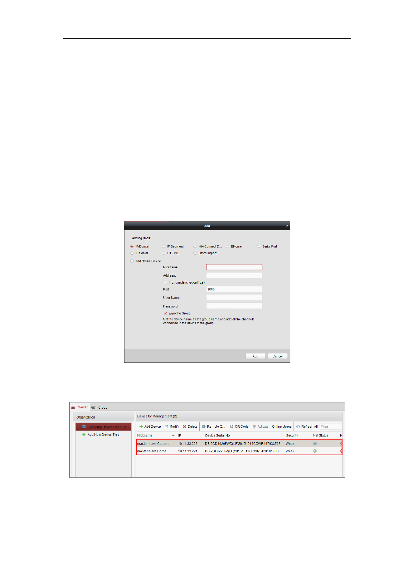
5.1.1 Add Devices
Go to Control Panel->Device Management->Server.
Add the box/bullet camera and speed dome to the client.
Steps:
1. Select the camera or speed dome to be added from the list.
2. Click Add to open the device adding dialog box.
3. Enter the required information.
Figure 5-1 Dialog Box of Adding Device
4. Click Add to add the device.
Figure 5-2 Devices Added

User Manual of Thermal Smart Linkage Tracking System
32
For detailed information, refer to user manual of the client software.
5.1.2 Live View
Steps:
1. Click the icon on the control panel, or click View->Main View to open the
Main View page.
2. In the left bottom area, select the cameras you added.
3. Click Add to Client to open the device adding dialog box.
4. Input the required information.
You can drag the camera/group to the display window, or double-click the
camera/group name in custom view mode to start the live view.
Figure 5-3 Live View Interface of Smart Linkage System
If you use third party VMS software, please contact technical support of our
branch for camera firmware.
For detailed information about client software of our company, please refer to the
user manual of the software. This manual mainly introduces accessing to the network
speed dome by web browser.

User Manual of Thermal Smart Linkage Tracking System
33
Chapter 6 Remote Configuration
6.1 Login the Speed Dome
Steps:
1. Click to select the camera on the camera list.
2. Right-click to show the menu and select Remote Configuration.
Figure 6-1 Remote Configuration Menu
You are highly recommended to close the live view of camera and speed dome and perform
the remote configuration operations to avoid slowing your PC.
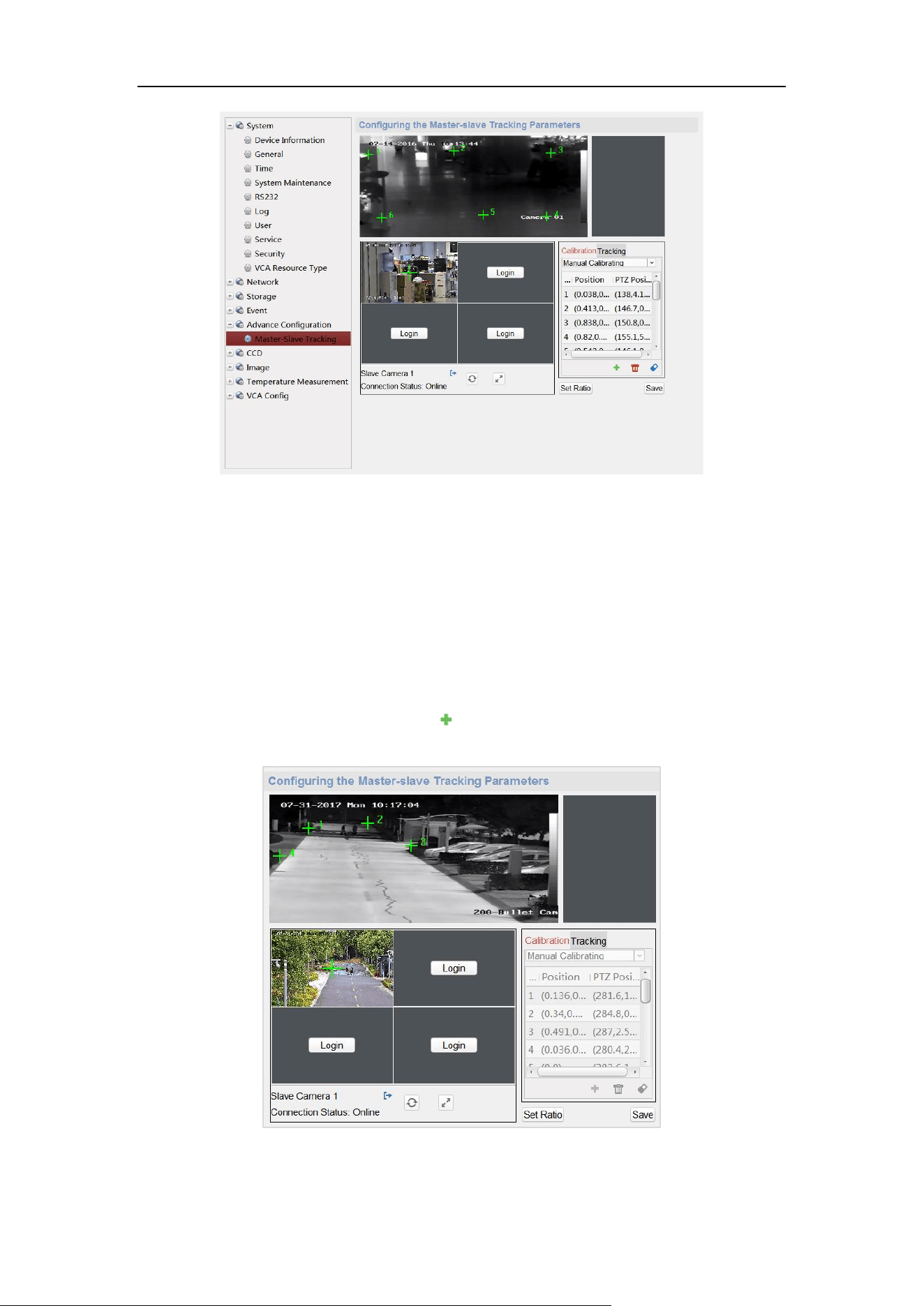
3. Login the speed dome to the Smart Linkage system.
1) In the Remote Configuration interface, go to Advanced Configuration > Smart
Linkage Tracking.
Figure 6-2 Smart Linkage Tracking Configuration Interface
User Manual of Thermal Smart Linkage Tracking System
34
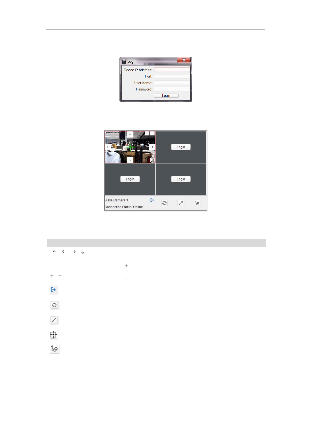
2) Click Login button to pop up the speed dome login dialog box.
3) Enter the required information.
Figure 6-3 Login Speed Dome
The description of Smart Linkage tracking parameters configuration interface
is shown below:
Figure 6-4 Smart Linkage Tracking Parameters Configuration
Table 6-1 Icon Description
Icon
Description
Direction Buttons of speed dome
Click , and the lens zooms in.
Click , and the lens zooms out.
Logout the speed dome from the system.
Refresh the live view of speed dome.
Display in 2:2/full screen window size.
3D Positioning
Save position
4. Click PTZ, and use the direction arrows to adjust the speed dome to a horizontal
position.
User Manual of Thermal Smart Linkage Tracking System
35
Figure 6-5 Smart Linkage Tracking Parameters
6.2 Calibration
6.2.1 Set Manual Calibration
Steps:
1. In the Calibration tab, select Manual Calibrating.
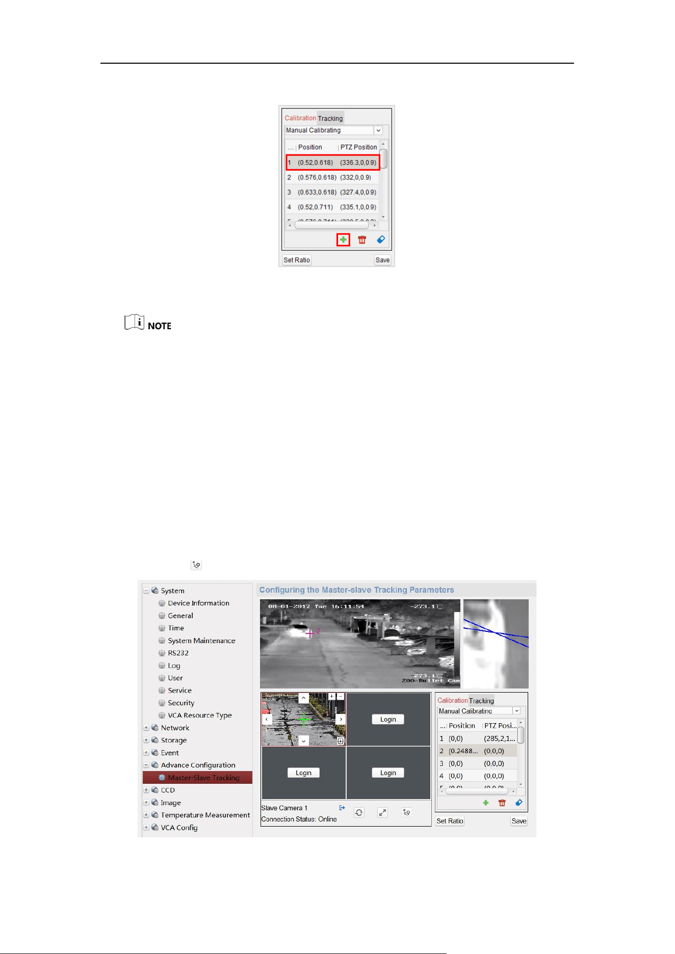
2. Select No. 1 from the list and click , a green cross appears in the center of the
live view page, and the digital zoom view of the selected site appears on the right.
Figure 6-6 Draw Calibration Point
User Manual of Thermal Smart Linkage Tracking System
36
3. Select No. 2 to No. 4, and repeat the step above to add the manual calibration sites.
Figure 6-7 Adding Calibration Sites
For each speed dome of the system, you shall add at least 4 calibration sites.
4 to 12 calibration sites can be configured. The Smart Linkage tracking gets
more accurate when you set more calibration sites.
The calibration sites should be separated evenly in the live view page.
Make sure all calibration sites are in the same actual plane. Do not set the
calibration sites in different planes to ensure the calibration effect.
Do not set multiple points on the same line, if so, one point of them will not
be useful for the calibration.
All the calibration sites should be set on the ground. If not, the PTZ camera
will track inaccurately
4. Perform the calibration operation.
1) Select calibration site No. 1 and the digital zoom view of site No. 1 appears
on the right.
2) Move and zoom in/out the speed dome to make sure the live views of dome
and the digital zoom view of selected site is mostly the same.
3) Click to save the current site position information.
Figure 6-8 Manual Calibration

User Manual of Thermal Smart Linkage Tracking System
37
4) Select No. 2 to No. 4, and repeat the steps above to save the site position
information.
5. Set the zoom ratio.
1) Enter Remote Configuration->Smart Linkage Tracking interface.
2) Adjust the zoom ratio of speed dome until the live view of speed dome is
mostly the same with the view of target frame of camera.
6. Click Save. The calibration is completed when Calibration Succeeded shows.
6.2.2 Set Auto Calibration
Before you start:
Make sure that the initial scenes of bullet camera and PTZ camera are same.
Select the resolution of PTZ camera as 1920 × 1080, and select the VCA resource
type of bullet camera as Behavior Analysis.
Steps:
1. In the Calibration tab, select Auto Calibrating.
2. Click Save when Calibration Succeeded shows.
6.3 Calibration Veryfication
Purpose:
Test the Smart Linkage tracking effect to verify the calibration accuracy.
Steps:
1. Exit the remote configuration interface of the camera to enter the live view
interface.
2. Right-click on the live view window of camera to show the menu and click Smart
Linkage.

User Manual of Thermal Smart Linkage Tracking System
38
Figure 6-9 Menu
3. Drag a rectangular frame in the camera live view window, and the speed dome
tracks.
What to Do Next:
If the center of speed dome view is the same as the mouse of camera view, and the
view of the frame is at the center of the speed dome view, the calibration is succeeded.
If not, repeat steps of Section 6.2 to perform the calibration once again.
6.4 Set Tracking Parameters
Purpose:
Set the tracking parameters, such as enable the Auto-tracking continuously or Auto-
tracking by Schedule, set tracking time, and Self-adaptive Ratio Coefficient.
Steps:
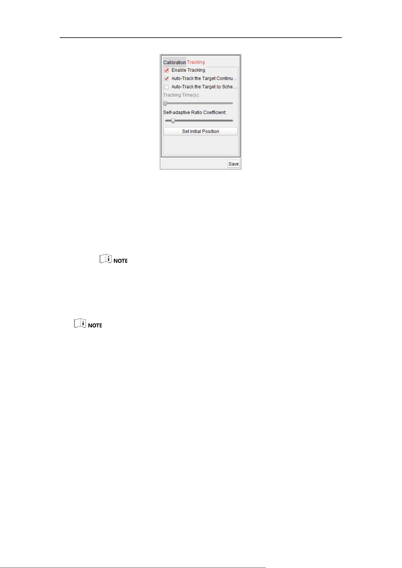
1. Enable tracking.
2. Select Tracking tab page, and then check the checkbox of Enable Tracking.
User Manual of Thermal Smart Linkage Tracking System
39
Figure 6-10 Tracking Tab Page
3. Set the tracking mode to Auto-Track the Target Continuously or Auto-Track the
Target by Schedule:
Auto-Track the Target Continuously: the speed dome tracks the target
continuously.
Auto-Track the Target by Schedule: the speed dome tracks the target by
schedule. Drag the time bar to set the tracking duration [Range: 0 to 60s].
If the duration is set to be 0, it works the same way as Auto-Track the Target
Continuously.
4. Set the self-adaptive ratio coefficient [Range: 0 to 60]. The recommended
coefficient value is 7.
Set the self-adaptive ratio coefficient according to the target size.
When the self-adaptive ratio coefficient value is not 0, the zoom ratio does not make
effect. The ratio of the speed dome changes with the target size.
Set the self-adaptive ratio coefficient value larger if you want to view less details of
the target. Set the self-adaptive ratio coefficient value smaller if you want to view
more details.
5. Move and zoom the speed dome to a scene, and then click the Set Initial Position
to set the initial position of speed dome. The speed dome moves to the initial
position after completing the tracking task.
6. Click Save to save the settings.
6.5 VCA Rule Configuration
Purpose:
Set the VCA rules of the Smart Linkage tracking, and then the speed dome perform
the tracking of target according to the rule.

User Manual of Thermal Smart Linkage Tracking System
40
Steps:
1. Select Camera No.1.
2. Enter Remote Configuration -> Basic -> VCA -> Rule.
3. Click of Rule List to add rule. You can set the rule according to VCA Operation
Guide.
Figure 6-11 VCA Operation Guide
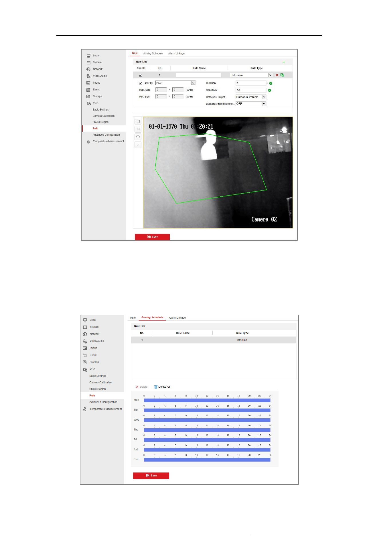
4. Select Intrusion as Event Type, and then click to draw the zone of intrusion
rule and click Save to save the settings.
User Manual of Thermal Smart Linkage Tracking System
41
Figure 6-12 Setting VCA Rule
5. Set the arming schedule of task. (Optional)
1) Enter Remote Configuration -> Basic -> VCA -> Rule -> Arming Schedule.
2) Select a rule from the rule list.
3) Drag the time bar to set the arming schedule of task.
4) Click Save to save the settings.

User Manual of Thermal Smart Linkage Tracking System
42
Figure 6-13 Setting Arming Schedule
6. Set the alarm linkage actions. (Optional)
1) Enter Remote Configuration -> Basic -> VCA -> Rule -> Alarm Linkage.
2) Check the checkbox to select the linkage method. Notify surveillance center,
send email, upload to FTP, trigger channel and trigger alarm output are
selectable.
3) Click Save to save the settings.
Figure 6-14 Setting Linkage Action
7. Set the shield region to shield this area. (Optional)
1) Enter Remote Configuration -> Basic -> VCA -> Shield Region.
2) Click to draw the shield region.
3) Click Save to save the settings.

User Manual of Thermal Smart Linkage Tracking System
43
Chapter 7 Auto Smart Linkage
Tracking
Steps:
1. Enter the live view interface of selected camera.
2. Right-click on the live view window of camera to show the menu and click Smart
Linkage.
3. When configured VCA rule is triggered by target, the speed dome performs the
automatic Smart Linkage tracking and the target frame turns from green into red.
Figure 7-1 Smart Linkage Tracking
For detailed information of functions of iVMS-4200, please refer to the user manual of
iVMS-4200 client software.

User Manual of Thermal Smart Linkage Tracking System
44
Appendix
Frequently Asked Questions (FAQ)
Device Running Error
Question:
The device fails to start up or reboots repeatedly.
The device constantly powers off unexpectedly when you pan/tilt the device or call preset.
The device fails to zoom in/out or pan/tilt.
Answer:
Examine the power supply of the positioning system and see whether it meets the
requirements.
Select the power supply as close as possible.
Examine the power cord and see whether it meets the requirements.
Device Upgrading
Question:
Device fails to upgrade.
Answer:
Examine if the device upgrading fails because of the poor network.
Examine if the upgrading program matches with the device type.
Others
Question:
The device live view is vague.
Answer:
Examine if you removed the protective film.
Examine if the lens is dirty or not.
Examine if any obstruction is nearby, e.g. spider web.
Question:
Live view fails with good network connection.
Answer:
Examine if the IE plug-in is well installed. Change the Website Blocker settings if necessary.
For cross-domain routing, enable the UPnP of device, or set manual mapping to port No.
80, 8000, or 554.
Examine if the live view channel amount exceeds the upper limit.
Examine the network bandwidth.
Question:
Focus fails when you test outdoor device in indoor situation.
Answer:
Restore the device to default settings.
Adjust the Min. Focusing Distance in Configuration > Image> Display Settings > Focus

User Manual of Thermal Smart Linkage Tracking System
45
Common Material Emissivity Reference
Material
Emissivity
Human Skin
0.98
PCB
0.91
Cement Concrete
0.95
Ceramics
0.92
Rubber
0.95
Paint
0.93
Wood
0.85
Asphalt
0.96
Brick
0.95
Sand
0.90
Soil
0.92
Cotton
0.98
Cardboard
0.90
White Paper
0.90
Water
0.96

User Manual of Thermal Smart Linkage Tracking System
46
UD22507B-B
