OWNER’S GUIDE & SERVICE MANUAL
MARVEL UNDERCOUNTER REFRIGERATION
Model: MOCR215-SS01B
WELCOME
Welcome to the Marvel Experience!
Thank you for choosing our quality American-built product
to add to your home. We are thrilled to welcome you to
our growing community of Marvel owners, who trust in our
products and our support.
The information in this guide is intended to help you install
and maintain your new Marvel undercounter model to
protect and prolong its lifetime. We encourage you to
contact our Technical Support team at (616) 754-5601 with
any questions.
Got a Marvelous Design?
We would love to see how your Marvel product looks in its
new home. You can send us photos of your installed
product at [email protected], and we
might feature your Marvel home design on our website and
social media!
Online registration
available at
marvelrefrigeration.com
Warranty Registration
It is important you register your product warranty after
taking delivery of your appliance. You can register online at
www.marvelrefrigeration.com.
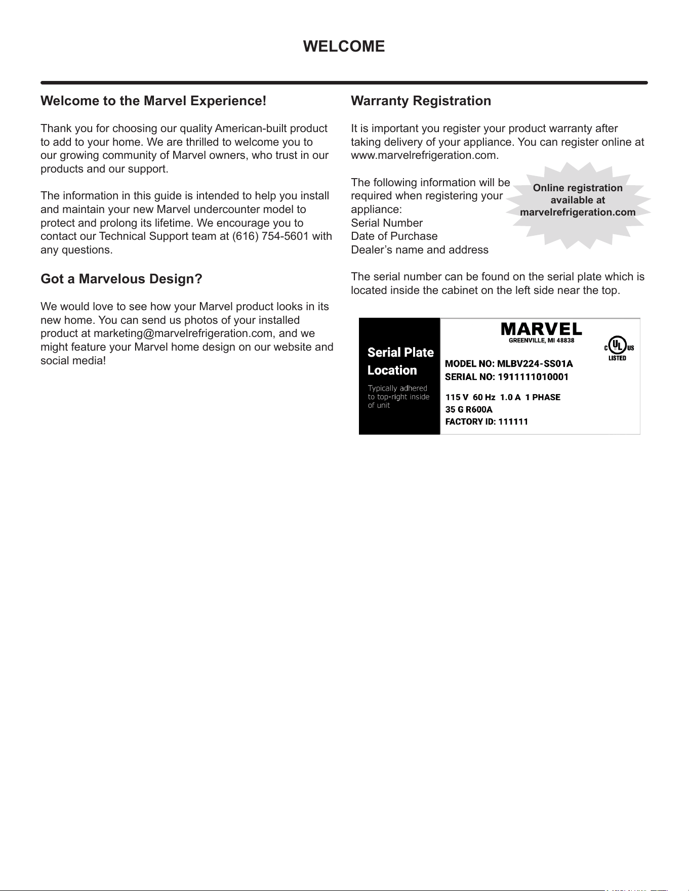
The following information will be
required when registering your
appliance:
Serial Number
Date of Purchase
Dealer’s name and address
The serial number can be found on the serial plate which is
located inside the cabinet on the left side near the top.
IMPORTANT SAFETY INSTRUCTIONS
Important Safety Instructions
Warnings and safety instructions appearing in this guide
are not meant to cover all possible conditions and
situations that may occur. Common sense, caution and
care must be exercised when installing, maintaining or
operating this appliance.
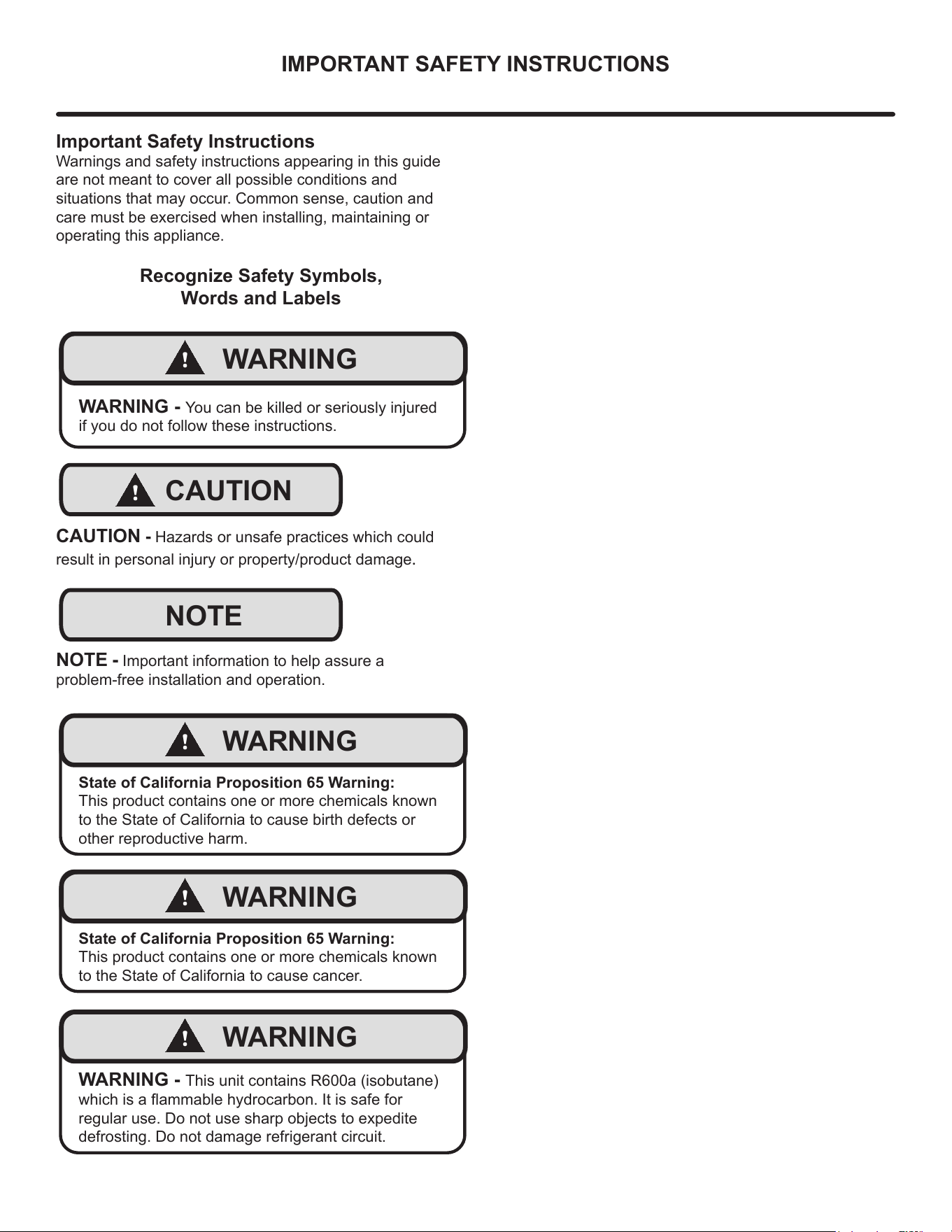
Recognize Safety Symbols,
Words and Labels
!
WARNING
WARNING - You can be killed or seriously injured
if you do not follow these instructions.
!
CAUTION
CAUTION - Hazards or unsafe practices which could
result in personal injury or property/product damage.
NOTE
NOTE - Important information to help assure a
problem-free installation and operation.
!
WARNING
State of California Proposition 65 Warning:
This product contains one or more chemicals known
to the State of California to cause birth defects or
other reproductive harm.
!
WARNING
State of California Proposition 65 Warning:
This product contains one or more chemicals known
to the State of California to cause cancer.
!
WARNING
WARNING - This unit contains R600a (isobutane)
which is a ammable hydrocarbon. It is safe for
regular use. Do not use sharp objects to expedite
defrosting. Do not damage refrigerant circuit.
3
UNPACKING YOUR APPLIANCE
!
WARNING
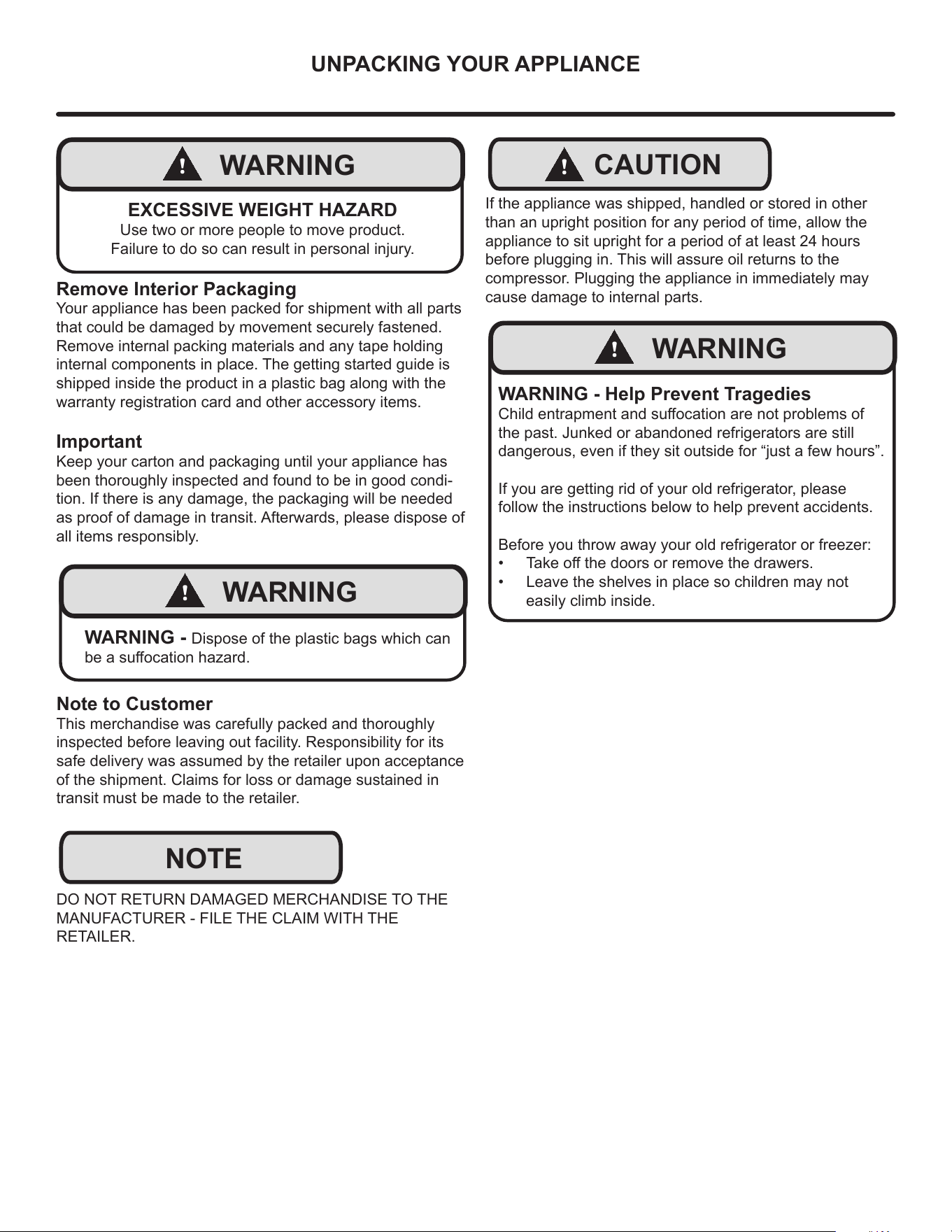
EXCESSIVE WEIGHT HAZARD
Use two or more people to move product.
Failure to do so can result in personal injury.
Remove Interior Packaging
Your appliance has been packed for shipment with all parts
that could be damaged by movement securely fastened.
Remove internal packing materials and any tape holding
internal components in place. The getting started guide is
shipped inside the product in a plastic bag along with the
warranty registration card and other accessory items.
Important
Keep your carton and packaging until your appliance has
been thoroughly inspected and found to be in good condi-
tion. If there is any damage, the packaging will be needed
as proof of damage in transit. Afterwards, please dispose of
all items responsibly.
!
WARNING
WARNING - Dispose of the plastic bags which can
be a suocation hazard.
Note to Customer
This merchandise was carefully packed and thoroughly
inspected before leaving out facility. Responsibility for its
safe delivery was assumed by the retailer upon acceptance
of the shipment. Claims for loss or damage sustained in
transit must be made to the retailer.
DO NOT RETURN DAMAGED MERCHANDISE TO THE
MANUFACTURER - FILE THE CLAIM WITH THE
RETAILER.
NOTE
!
CAUTION
If the appliance was shipped, handled or stored in other
than an upright position for any period of time, allow the
appliance to sit upright for a period of at least 24 hours
before plugging in. This will assure oil returns to the
compressor. Plugging the appliance in immediately may
cause damage to internal parts.
!
WARNING
WARNING - Help Prevent Tragedies
Child entrapment and suocation are not problems of
the past. Junked or abandoned refrigerators are still
dangerous, even if they sit outside for “just a few hours”.
If you are getting rid of your old refrigerator, please
follow the instructions below to help prevent accidents.
Before you throw away your old refrigerator or freezer:
• Take o the doors or remove the drawers.
• Leave the shelves in place so children may not
easily climb inside.
4
ELECTRICAL
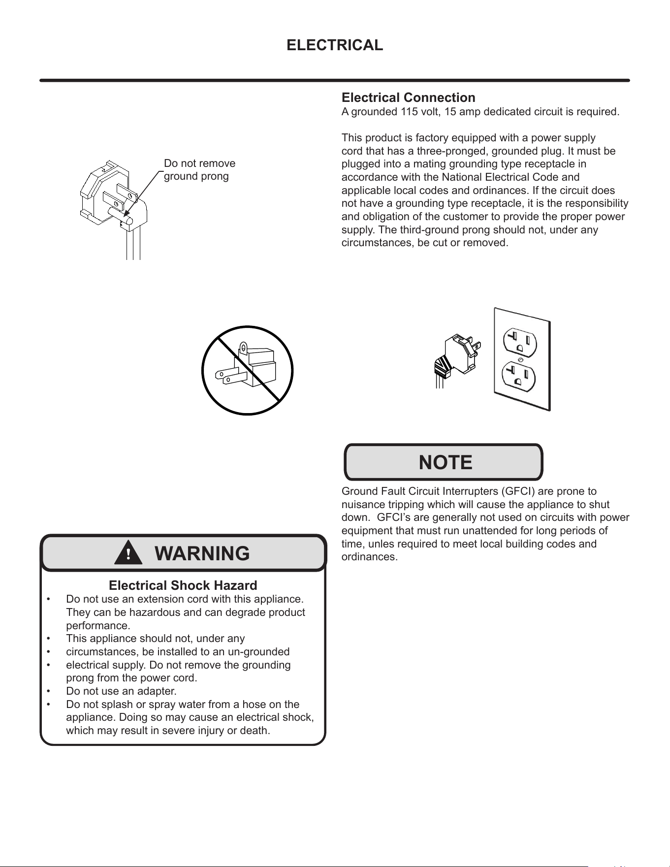
Do not remove
ground prong
!
WARNING
Electrical Shock Hazard
• Do not use an extension cord with this appliance.
They can be hazardous and can degrade product
performance.
• This appliance should not, under any
• circumstances, be installed to an un-grounded
• electrical supply. Do not remove the grounding
prong from the power cord.
• Do not use an adapter.
• Do not splash or spray water from a hose on the
appliance. Doing so may cause an electrical shock,
which may result in severe injury or death.
Electrical Connection
A grounded 115 volt, 15 amp dedicated circuit is required.
This product is factory equipped with a power supply
cord that has a three-pronged, grounded plug. It must be
plugged into a mating grounding type receptacle in
accordance with the National Electrical Code and
applicable local codes and ordinances. If the circuit does
not have a grounding type receptacle, it is the responsibility
and obligation of the customer to provide the proper power
supply. The third-ground prong should not, under any
circumstances, be cut or removed.
NOTE
Ground Fault Circuit Interrupters (GFCI) are prone to
nuisance tripping which will cause the appliance to shut
down. GFCI’s are generally not used on circuits with power
equipment that must run unattended for long periods of
time, unles required to meet local building codes and
ordinances.
5
CUTOUT AND PRODUCT DIMENSIONS
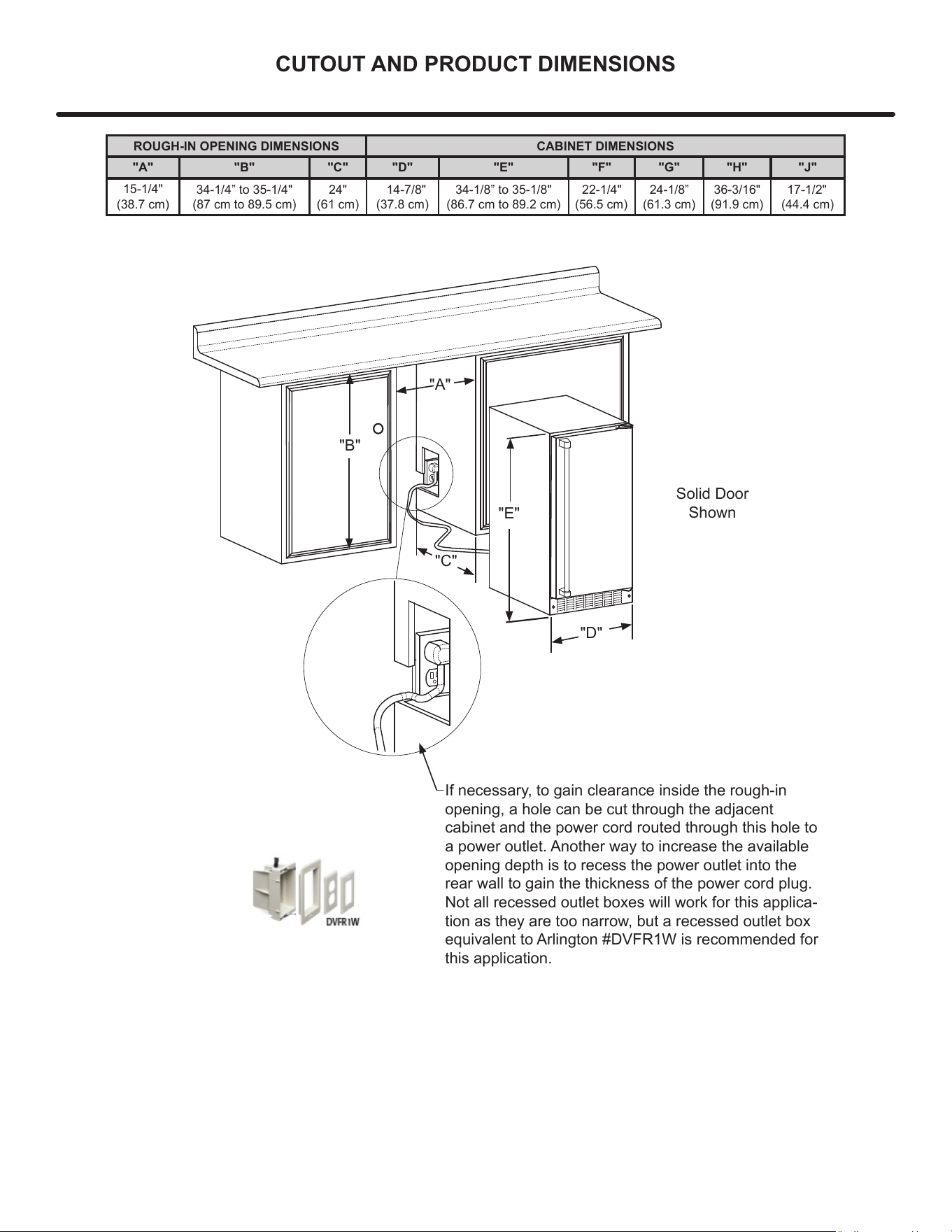
ROUGH-IN OPENING DIMENSIONS CABINET DIMENSIONS
"A" "B" "C" "D" "E" "F" "G" "H" "J"
15-1/4"
(38.7 cm)
34-1/4” to 35-1/4"
(87 cm to 89.5 cm)
24"
(61 cm)
14-7/8"
(37.8 cm)
34-1/8” to 35-1/8"
(86.7 cm to 89.2 cm)
22-1/4"
(
56.5 cm)
24-1/8”
(
61.3 cm)
36-3/16"
(
91.9 cm)
17-1/2"
(
44.4 cm)
"A"
"B"
"C"
"D"
"E"
If necessary, to gain clearance inside the rough-in
opening, a hole can be cut through the adjacent
cabinet and the power cord routed through this hole to
a power outlet. Another way to increase the available
opening depth is to recess the power outlet into the
rear wall to gain the thickness of the power cord plug.
Not all recessed outlet boxes will work for this applica-
tion as they are too narrow, but a recessed outlet box
equivalent to Arlington #DVFR1W is recommended for
this application.
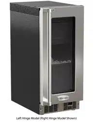
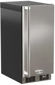
Solid Door
Shown
6
CUTOUT AND PRODUCT DIMENSIONS
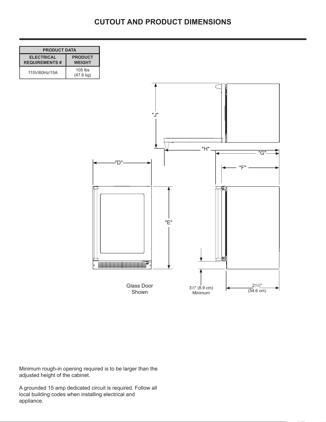
PRODUCT DATA
ELECTRICAL
REQUIREMENTS #
PRODUCT
WEIGHT
115V/60Hz/15A
105 lbs
(47.6 kg)
Minimum rough-in opening required is to be larger than the
adjusted height of the cabinet.
A grounded 15 amp dedicated circuit is required. Follow all
local building codes when installing electrical and
appliance.
3
1
/2" (8.9 cm)
Minimum
"D"
"E"
"F"
"G"
"J"
Glass Door
Shown
21
1
/2"
(54.6 cm)
"H"
7
INSTALLING YOUR APPLIANCE
General Installation
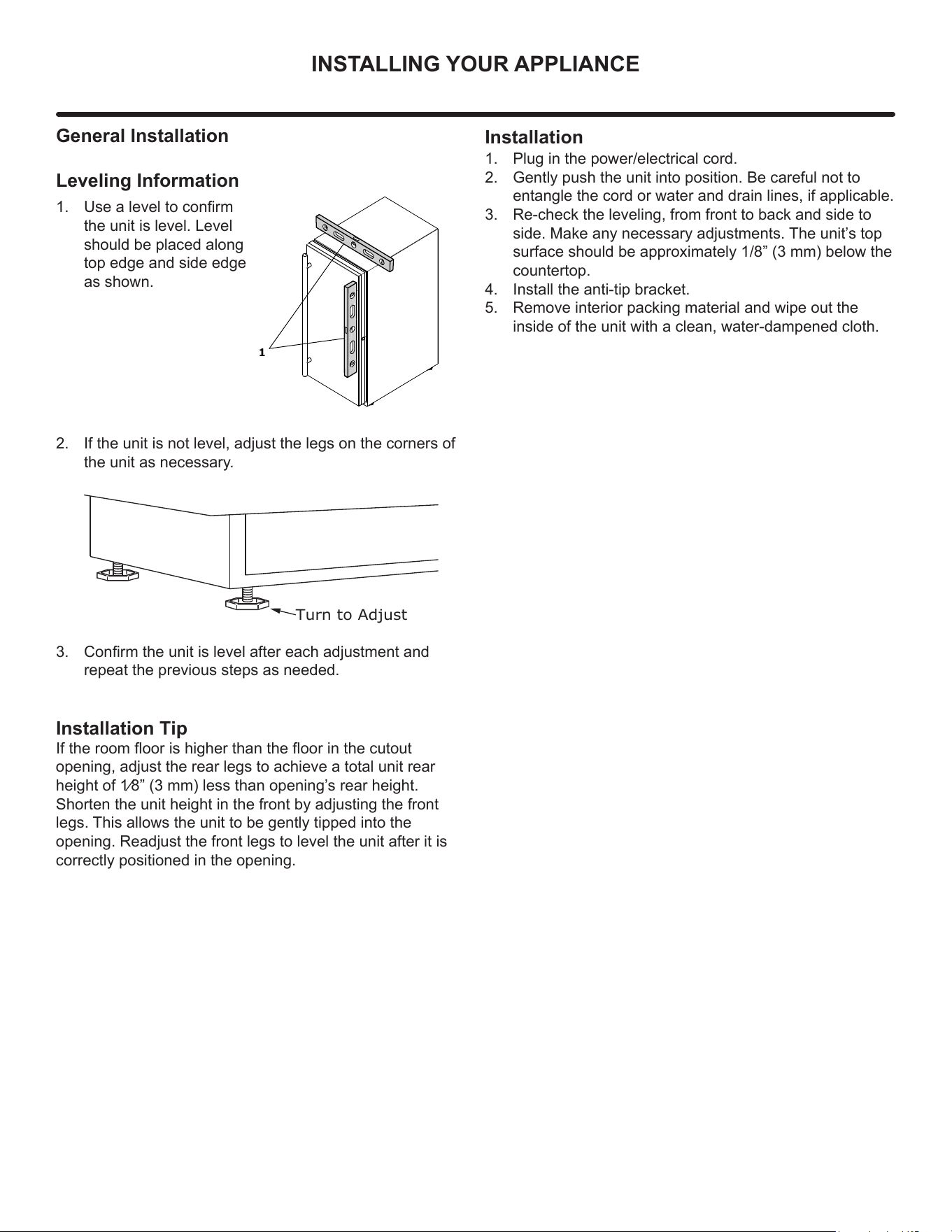
Leveling Information
1. Use a level to conrm
the unit is level. Level
should be placed along
top edge and side edge
as shown.
2. If the unit is not level, adjust the legs on the corners of
the unit as necessary.
3. Conrm the unit is level after each adjustment and
repeat the previous steps as needed.
1
Turn to Adjust
Installation Tip
If the room oor is higher than the oor in the cutout
opening, adjust the rear legs to achieve a total unit rear
height of 1⁄8” (3 mm) less than opening’
s rear height.
Shorten the unit height in the front by adjusting the front
legs. This allows the unit to be gently tipped into the
opening. Readjust the front legs to level the unit after it is
correctly positioned in the opening.
Installation
1. Plug in the power/electrical cord.
2. Gently push the unit into position. Be careful not to
entangle the cord or water and drain lines, if applicable.
3. Re-check the leveling, from front to back and side to
side. Make any necessary adjustments. The unit’s top
surface should be approximately 1/8” (3 mm) below the
countertop.
4. Install the anti-tip bracket.
5. Remove interior packing material and wipe out the
inside of the unit with a clean, water-dampened cloth.
8
Side-by-Side Installation
Two units may be installed side-by-side.
Cutout width for a side-by-side installation is the cutout
dimension of a single unit times two.
No trim kit is required. However, 1/4" (6 mm) of space
needs to be maintained between the units to ensure
unobstructed door swing.
Units must operate from separate, properly grounded
electrical receptacles placed according to each unit’s
electrical specifications requirements.
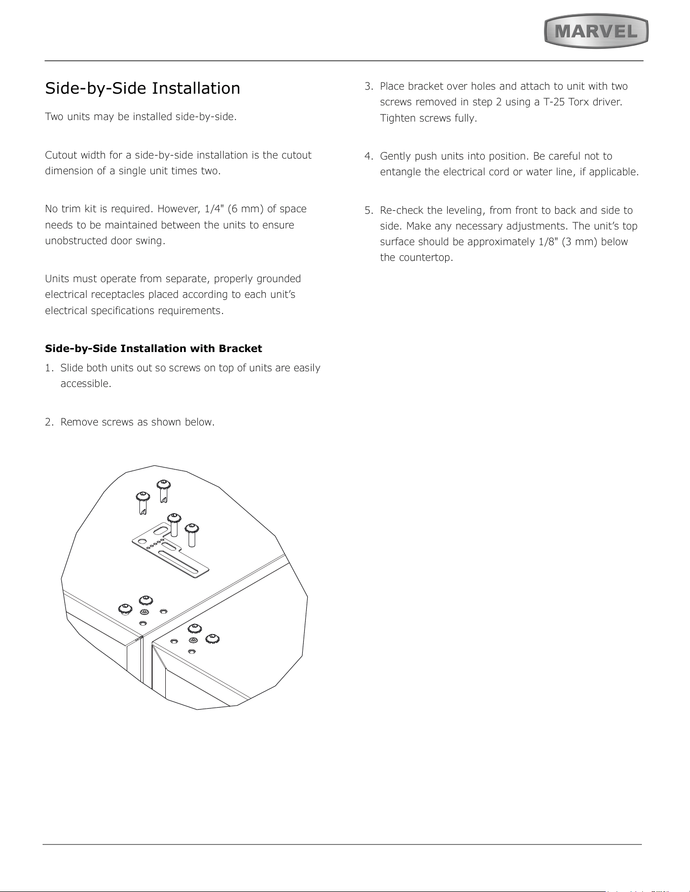
Side-by-Side Installation with Bracket
1. Slide both units out so screws on top of units are easily
accessible.
2. Remove screws as shown below.
3. Place bracket over holes and attach to unit with two
screws removed in step 2 using a T-25 Torx driver.
Tighten screws fully.
4. Gently push units into position. Be careful not to
entangle the electrical cord or water line, if applicable.
5. Re-check the leveling, from front to back and side to
side. Make any necessary adjustments. The unit’s top
surface should be approximately 1/8" (3 mm) below
the countertop.
9
INSTALLING THE ANTI-TIP DEVICE
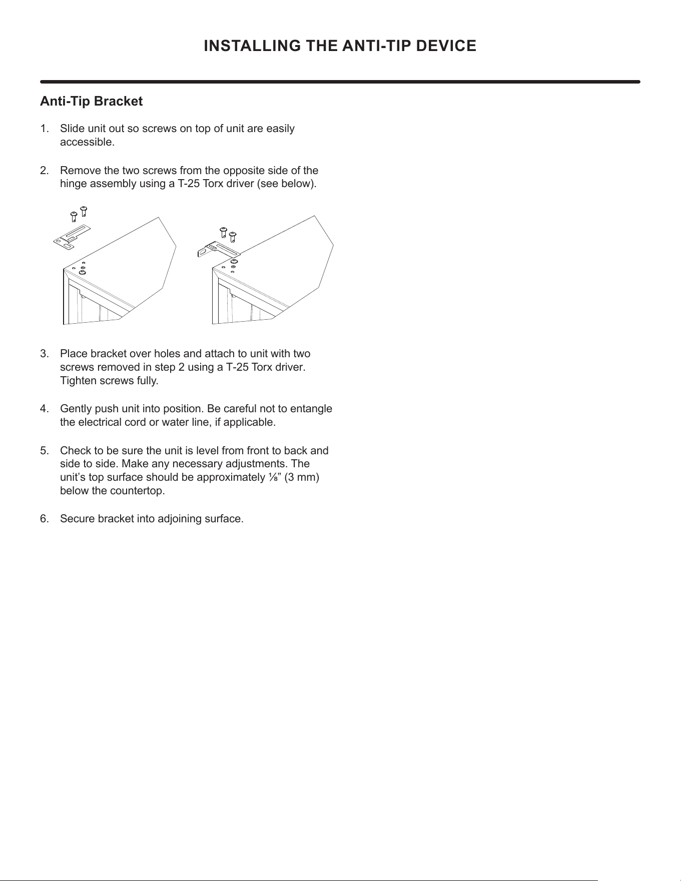
Anti-Tip Bracket
1. Slide unit out so screws on top of unit are easily
accessible.
2. Remove the two screws from the opposite side of the
hinge assembly using a T-25 Torx driver (see below).
Place bracket over holes and attach to unit with two
screws removed in step 2 using a T-25 Torx driver.
Tighten screws fully.
Gently push unit into position. Be careful not to entangle
the electrical cord or water line, if applicable.
Check to be sure the unit is level from front to back and
side to side. Make any necessary adjustments. The
unit’s top surface should be approximately ¹»” (3 mm)
below the countertop.
Secure bracket into adjoining surface.
10
DOOR REVERSAL
Door Adjustments
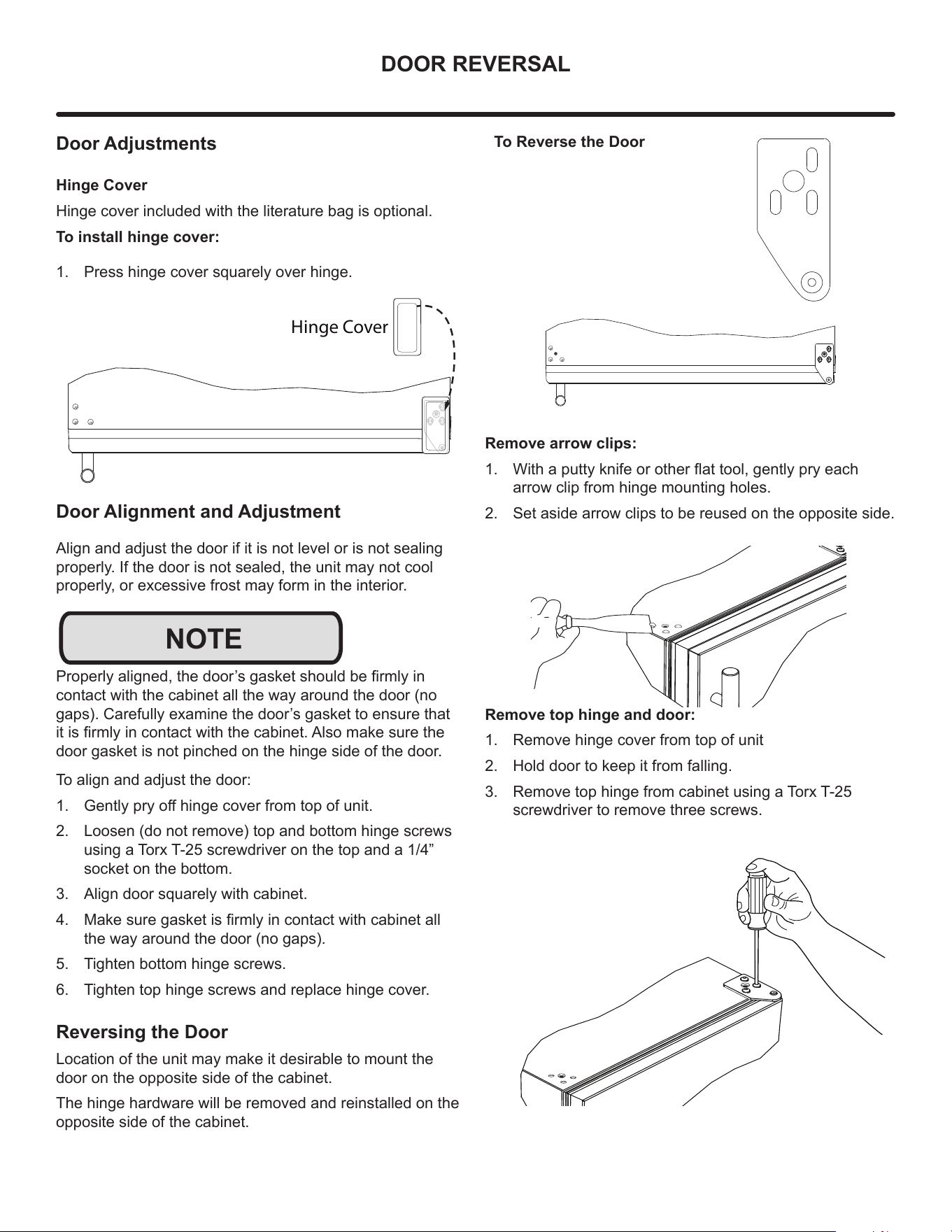
Hinge Cover
Hinge cover included with the literature bag is optional.
To install hinge cover:
1. Press hinge cover squarely over hinge.
Door Alignment and Adjustment
Align and adjust the door if it is not level or is not sealing
properly. If the door is not sealed, the unit may not cool
properly, or excessive frost may form in the interior.
3URSHUO\DOLJQHGWKHGRRU¶VJDVNHWVKRXOGEH¿UPO\LQ
contact with the cabinet all the way around the door (no
gaps). Carefully examine the door’s gasket to ensure that
LWLV¿UPO\LQFRQWDFWZLWKWKHFDELQHW$OVRPDNHVXUHWKH
door gasket is not pinched on the hinge side of the door.
To align and adjust the door:
1. *HQWO\SU\RႇKLQJHFRYHUIURPWRSRIXQLW
2. Loosen (do not remove) top and bottom hinge screws
using a Torx T-25 screwdriver on the top and a 1/4”
socket on the bottom.
3. Align door squarely with cabinet.
4. 0DNHVXUHJDVNHWLV¿UPO\LQFRQWDFWZLWKFDELQHWDOO
the way around the door (no gaps).
5. Tighten bottom hinge screws.
6. Tighten top hinge screws and replace hinge cover.
Reversing the Door
Location of the unit may make it desirable to mount the
door on the opposite side of the cabinet.
The hinge hardware will be removed and reinstalled on the
opposite side of the cabinet.
Hinge Cover
NOTE
To Reverse the Door
Remove arrow clips:
1. :LWKDSXWW\NQLIHRURWKHUÀDWWRROJHQWO\SU\HDFK
arrow clip from hinge mounting holes.
2. Set aside arrow clips to be reused on the opposite side.
Remove top hinge and door:
1. Remove hinge cover from top of unit
2. Hold door to keep it from falling.
3. Remove top hinge from cabinet using a Torx T-25
screwdriver to remove three screws.
11
DOOR REVERSAL
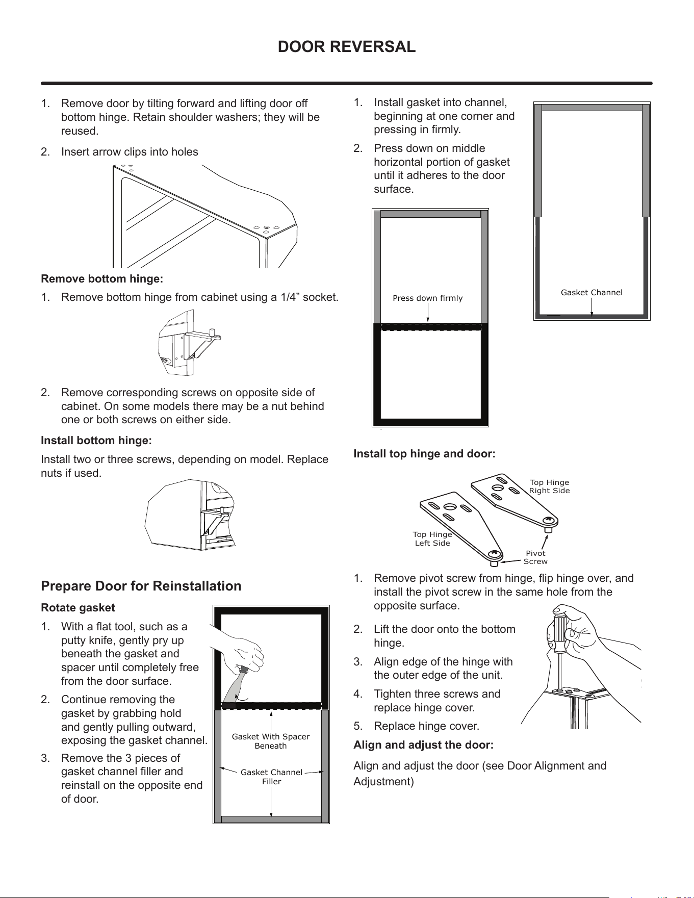
1. 5HPRYHGRRUE\WLOWLQJIRUZDUGDQGOLIWLQJGRRURႇ
bottom hinge. Retain shoulder washers; they will be
reused.
2. Insert arrow clips into holes
Remove bottom hinge:
1. Remove bottom hinge from cabinet using a 1/4” socket.
2. Remove corresponding screws on opposite side of
cabinet. On some models there may be a nut behind
one or both screws on either side.
Install bottom hinge:
Install two or three screws, depending on model. Replace
nuts if used.
Prepare Door for Reinstallation
Rotate gasket
1. :LWKDÀDWWRROVXFKDVD
putty knife, gently pry up
beneath the gasket and
spacer until completely free
from the door surface.
2. Continue removing the
gasket by grabbing hold
and gently pulling outward,
exposing the gasket channel.
3. Remove the 3 pieces of
gasket channel filler and
reinstall on the opposite end
of door.
Gasket Channel
Filler
Gasket With Spacer
Beneath
1. Install gasket into channel,
beginning at one corner and
pressing in firmly.
2. Press down on middle
horizontal portion of gasket
until it adheres to the door
surface.
Install top hinge and door:
1. 5HPRYHSLYRWVFUHZIURPKLQJHÀLSKLQJHRYHUDQG
install the pivot screw in the same hole from the
opposite surface.
2. Lift the door onto the bottom
hinge.
3. Align edge of the hinge with
the outer edge of the unit.
4. Tighten three screws and
replace hinge cover.
5. Replace hinge cover.
Align and adjust the door:
Align and adjust the door (see Door Alignment and
Adjustment)
Gasket Channel
3UHVVGRZQɟUPO\
Top Hinge
Right Side
Top Hinge
Left Side
Pivot
Screw
12
INSTALLING THE WATER SUPPLY
Prepare Plumbing
Plumbing installation must observe all state and local
codes. All water and drain connections MUST BE made by
DOLFHQVHGTXDOL¿HGSOXPELQJFRQWUDFWRU)DLOXUHWRIROORZ
recommendations and instructions may result in damage
and/or harm.
Water Supply Connection
:KHQFRQQHFWLQJWKHZDWHUVXSSO\SOHDVHQRWHWKH
IROORZLQJ
• %HIRUHLQVWDOOLQJWKHXQLWDQGFRQQHFWLQJWRWKHFROG
ZDWHUVXSSO\UHYLHZWKHORFDOSOXPELQJFRGHV
• 7KHZDWHUSUHVVXUHVKRXOGEHEHWZHHQDPLQLPXPRI
DQGDPD[LPXPRISVLDQGN3D
• :DWHUKDVOHVVWKDQPJ/SSPWRWDOGLVVROYHG
VROLGVDQGKDUGQHVVOHYHOEHORZPJ/SSP²LH
EHORZJUDLQVSHUJDOORQ&KHFNE\XVLQJ7'6PHWHU
RUFRQVXOWLQJZLWKORFDOZDWHUFRPSDQ\
• 7'6DQGRUZDWHUKDUGQHVVDERYHWKHVHOLPLWVVKRXOG
be treated with a reverse osmosis system or other
¿OWUDWLRQV\VWHP
• 6RIWHQHGZDWHULVQRWUHFRPPHQGHGDVLWPD\UHVXOWLQ
VRIWHULFHWKDQGHVLUHG
• &RQQHFWLRQWRWKHZDWHUPDLQLVPDGHZLWKKRVHVHW
only.
• +RVHVHWPXVWEHQHZQRWUHXVHGDQGLQFRPSOLDQFH
ZLWK,(&
• 7KHZDWHUOLQH0867KDYHDVKXWRႇYDOYHLQWKH
VXSSO\OLQH
• 7KHZDWHUOLQHVKRXOGEHORRSHGLQWRFRLOV7KLVZLOO
DOORZWKHXQLWWREHUHPRYHGIRUFOHDQLQJDQGVHUYLFLQJ
0DNHFHUWDLQWKDWWKHWXELQJLVQRWSLQFKHGRUGDPDJHG
during installation.
!
CAUTION
'RQRWXVHDQ\SODVWLFZDWHUVXSSO\OLQH7KHOLQHLVXQGHU
SUHVVXUHDWDOOWLPHV3ODVWLFPD\FUDFNRUUXSWXUHZLWKDJH
DQGFDXVHGDPDJHWR\RXUKRPH'RQRWXVHWDSHRUMRLQW
FRPSRXQGZKHQDWWDFKLQJDEUDLGHGÀH[LEOHZDWHUVXSSO\
OLQHWKDWLQFOXGHVDUXEEHUJDVNHW7KHJDVNHWSURYLGHV
DQDGHTXDWHVHDO±RWKHUPDWHULDOVFRXOGFDXVHEORFNDJH
RIWKHYDOYH)DLOXUHWRIROORZUHFRPPHQGDWLRQVDQG
LQVWUXFWLRQVPD\UHVXOWLQGDPDJHDQGRUKDUPÀRRGLQJRU
YRLGWKHSURGXFWZDUUDQW\8VHQHZKRVHVHW'RQRWUHXVH
old hose set.
7XUQRႇZDWHUVXSSO\DQGGLVFRQQHFWHOHFWULFDOVXSSO\WR
XQLWSULRUWRLQVWDOODWLRQ8VHFDXWLRQZKHQKDQGOLQJEDFN
SDQHO7KHHGJHVFRXOGEHVKDUS
!
CAUTION
!
CAUTION
13
INSTALLING THE WATER SUPPLY
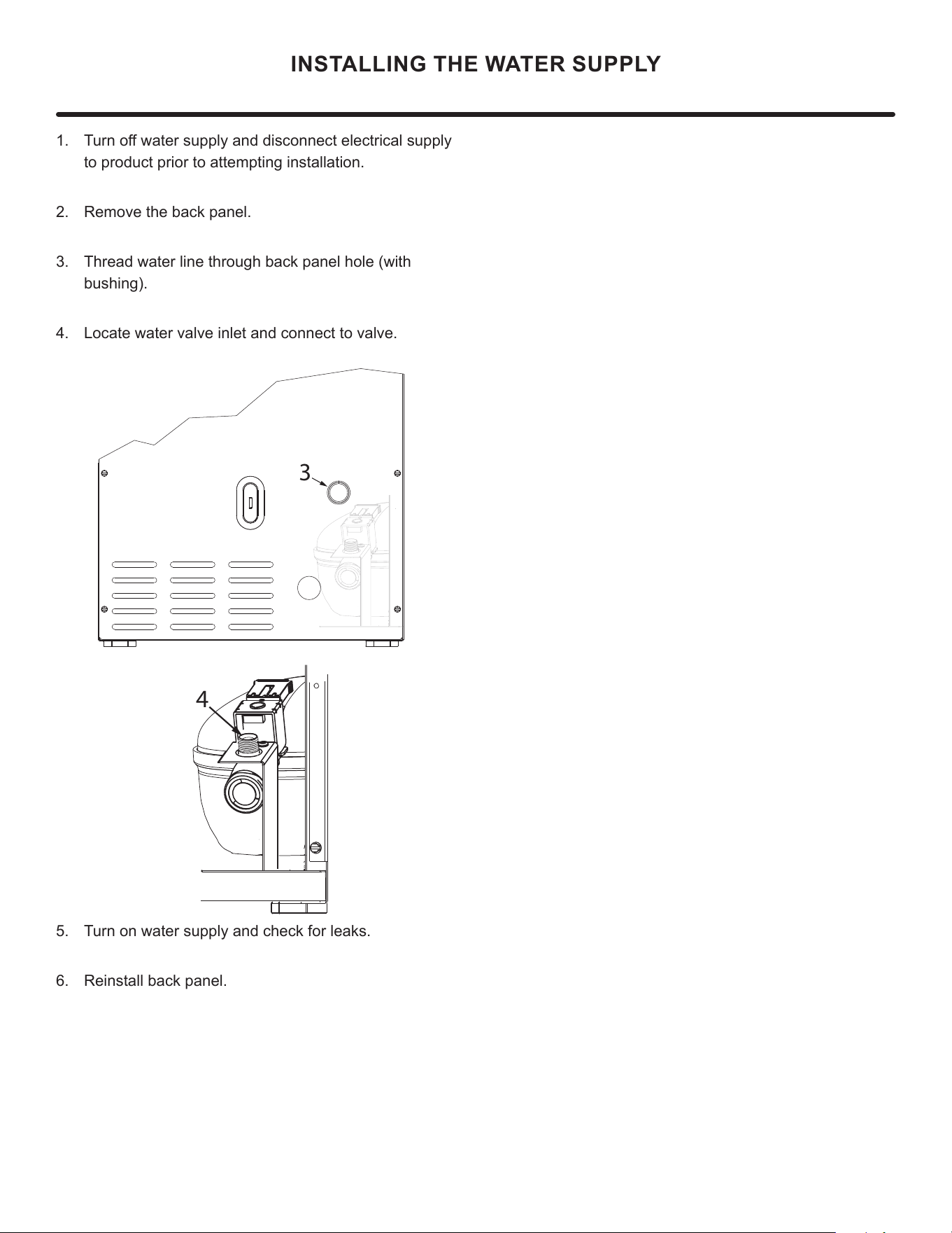
7XUQRႇZDWHUVXSSO\DQGGLVFRQQHFWHOHFWULFDOVXSSO\
WRSURGXFWSULRUWRDWWHPSWLQJLQVWDOODWLRQ
2. 5HPRYHWKHEDFNSDQHO
7KUHDGZDWHUOLQHWKURXJKEDFNSDQHOKROHZLWK
EXVKLQJ
4. Locate water valve inlet and connect to valve.
5. 7XUQRQZDWHUVXSSO\DQGFKHFNIRUOHDNV
5HLQVWDOOEDFNSDQHO
3
4
14
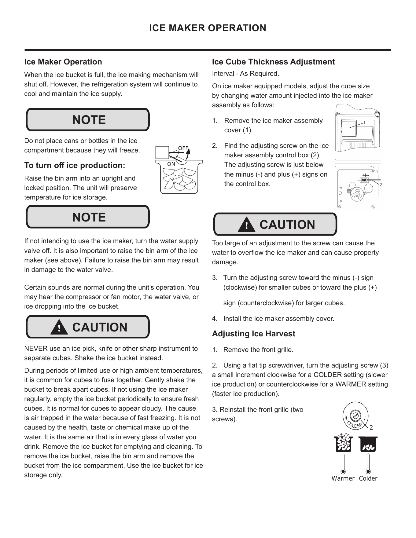
Ice Cube Thickness Adjustment
Interval - As Required.
On ice maker equipped models, adjust the cube size
by changing water amount injected into the ice maker
assembly as follows:
1. Remove the ice maker assembly
cover (1).
2. Find the adjusting screw on the ice
maker assembly control box (2).
The adjusting screw is just below
the minus (-) and plus (+) signs on
the control box.
Too large of an adjustment to the screw can cause the
ZDWHUWRRYHUÀRZWKHLFHPDNHUDQGFDQFDXVHSURSHUW\
damage.
3. Turn the adjusting screw toward the minus (-) sign
(clockwise) for smaller cubes or toward the plus (+)
sign (counterclockwise) for larger cubes.
4. Install the ice maker assembly cover.
Adjusting Ice Harvest
1. Remove the front grille.
8VLQJDÀDWWLSVFUHZGULYHUWXUQWKHDGMXVWLQJVFUHZ
a small increment clockwise for a COLDER setting (slower
ice production) or counterclockwise for a WARMER setting
(faster ice production).
3. Reinstall the front grille (two
screws).
Ice Maker Operation
When the ice bucket is full, the ice making mechanism will
VKXWRႇ+RZHYHUWKHUHIULJHUDWLRQV\VWHPZLOOFRQWLQXHWR
cool and maintain the ice supply.
Do not place cans or bottles in the ice
compartment because they will freeze.
7RWXUQRႇLFHSURGXFWLRQ
Raise the bin arm into an upright and
locked position. The unit will preserve
temperature for ice storage.
If not intending to use the ice maker, turn the water supply
YDOYHRႇ,WLVDOVRLPSRUWDQWWRUDLVHWKHELQDUPRIWKHLFH
maker (see above). Failure to raise the bin arm may result
in damage to the water valve.
Certain sounds are normal during the unit’s operation. You
may hear the compressor or fan motor, the water valve, or
ice dropping into the ice bucket.
NEVER use an ice pick, knife or other sharp instrument to
separate cubes. Shake the ice bucket instead.
During periods of limited use or high ambient temperatures,
it is common for cubes to fuse together. Gently shake the
bucket to break apart cubes. If not using the ice maker
regularly, empty the ice bucket periodically to ensure fresh
cubes. It is normal for cubes to appear cloudy. The cause
is air trapped in the water because of fast freezing. It is not
caused by the health, taste or chemical make up of the
water. It is the same air that is in every glass of water you
drink. Remove the ice bucket for emptying and cleaning. To
remove the ice bucket, raise the bin arm and remove the
bucket from the ice compartment. Use the ice bucket for ice
storage only.
ICE MAKER OPERATION
NOTE
NOTE
!
CAUTION
!
CAUTION
C
O
L
D
E
R
Warmer Colder
15
CARE AND CLEANING
Exterior Cleaning
Stainless door panels, handles and frames can discolor
when exposed to chlorine gas, pool chemicals, saltwater or
cleaners with bleach.
Keep your stainless unit looking new by cleaning with a
good quality all-in-one stainless steel cleaner and polish
monthly. For best results use Claire
®
Stainless Steel
Polish and Cleaner. Comparable products are acceptable.
Frequent cleaning will remove surface contamination that
could lead to rust. Some installations may require cleaning
weekly.
Do not clean with steel wool pads.
Do not use stainless steel cleaners or polishes on any
glass surfaces.
Clean any glass surfaces with a non-chlorine glass cleaner.
'RQRWXVHFOHDQHUVQRWVSHFL¿FDOO\LQWHQGHGIRUVWDLQOHVV
steel on stainless steel surfaces (this includes glass, tile,
and counter cleaners).
If any surface discoloring or rusting appears, clean it
quickly with Bon-Ami
®
or Barkeepers Friend Cleanser
®
and
a nonabrasive cloth. Always clean with the grain. Always
¿QLVKZLWK&ODLUH
®
Stainless Steel Polish and Cleaner or
comparable product to prevent further problems.
Using abrasive pads such as ScotchBrite™ will
cause the graining in the stainless steel to
become blurred.
Rust not cleaned up promptly can penetrate the
surface of the stainless steel and complete
removal of the rust may not be possible.
Integrated Models
To clean integrated panels, use household cleaner per the
cabinet manufacturer’s recommendations.
Interior Cleaning
Disconnect power to the unit.
Clean the interior and all removed components using a mild
nonabrasive detergent and warm solution applied with a soft
sponge or non-abrasive cloth.
Rinse the interior using a soft sponge and clean water.
Do not use any solvent-based or abrasive cleaners. These
types of cleaners may transfer taste and/or odor to the
interior products and damage or discolor the interior
.
Defrosting
This unit is a manual defrost model and will require
occasional defrosting. When there is build-up of 1/4”
(6 mm) or more of frost, manually defrost the unit.
DO NOT use an ice pick or other sharp instrument to help speed
up defrosting. These instruments can puncture the inner lining
or damage the cooling unit. DO NOT use any type of heater to
defrost. Using a heater to speed up defrosting can cause personal
injury and damage to the inner lining.
!
CAUTION
16
CARE AND CLEANING
To Defrost:
1. Disconnect power to the unit.
2. Remove ice bucket and discard ice.
3. Place towel or other absorbent material on bottom of
ice bin.
4. Fill the ice bucket half full with warm, not hot water.
This will help the unit defrost faster.
5. Place the ice bucket back into the unit on top of the
towel or other absorbent material.
6. Prop the door in an open position (2 in. [50 mm]
minimum).
7. After about 1 hour remove the ice bin and discard
water.
8. Allow the frost to melt naturally.
9. After the frost melts completely clean the interior and
all removed components. (See Interior Cleaning).
DO NOT clean ice bucket using a dishwasher. The bucket
is not dishwasher safe and will be damaged.
10. When the interior is dry, reconnect power and turn unit
on.
To safeguard against contaminates in ice, discard
¿UVWWKUHHEDWFKHVRILFHDIWHUGHIURVWLQJ
NOTE
NOTE
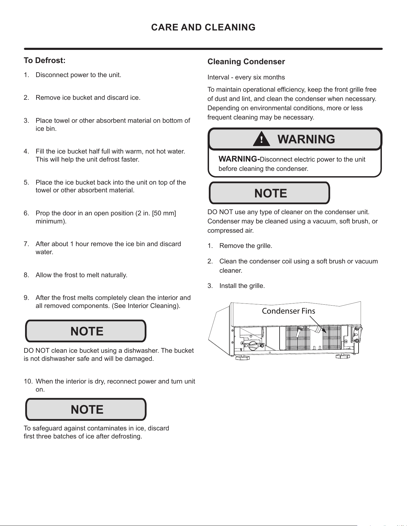
Cleaning Condenser
Interval - every six months
7RPDLQWDLQRSHUDWLRQDOHႈFLHQF\NHHSWKHIURQWJULOOHIUHH
of dust and lint, and clean the condenser when necessary.
Depending on environmental conditions, more or less
frequent cleaning may be necessary.
DO NOT use any type of cleaner on the condenser unit.
Condenser may be cleaned using a vacuum, soft brush, or
compressed air.
1. Remove the grille.
2. Clean the condenser coil using a soft brush or vacuum
cleaner.
3. Install the grille.
Condenser Fins
!
WARNING
WARNING-Disconnect electric power to the unit
before cleaning the condenser.
NOTE
17
STAINLESS STEEL MAINTENANCE
Background
Stainless steel does not stain, corrode, or rust as easily as
ordinary steel, but it is not stain or corrosion proof. Stain-
less steels can discolor or corrode if not maintained prop-
erly.
amount of chromium present. It is this chromium that
surface can be damaged or contaminated, which may
result in discoloration, staining, or corrosion of the base
metal.
Care & Cleaning
Routine cleaning of the stainless steel surfaces will serve to
greatly extend the life of your product by removing contami-
nants. This is especially important in coastal areas which
can expose the stainless to severe contaminants such as
It is strongly recommended to periodically inspect and thor-
oughly clean crevices, weld points, under gaskets, rivets,
bolt heads, and any locations where small amounts of liquid
could collect, become stagnant, and concentrate contami-
nates. Additionally, any mounting hardware that is showing
signs of corrosion should be replaced.
Frequency of cleaning will depend upon the installation
location, environmental, and usage conditions.
Choosing a Cleaning Product
The choice of a proper cleaning product is ultimately that
of the consumer, and there are many products from which
to choose. Depending upon the type of cleaning and the
degree of contamination, some products are better than
others.
cleaning of most stainless steel products is to give the sur-
faces a brisk rubbing with a soft cloth soaked in warm water
and a gentle detergent, or mild mixture of ammonia. Rub-
bing should, to the extent possible, follow the polish lines of
the steel, and always insure thorough rinsing after cleaning.
Although some products are called "stainless steel clean-
ers," some may contain abrasives which could scratch the
and some many contain chlorine bleach which will dull,
tarnish or discolor the surface if not completely removed.
After the stainless surfaces have been thoroughly cleaned,
a good quality car wax may be applied to help maintain the
Stainless steel products should never be installed, or stored
in close proximity to chlorine chemicals.
Whichever cleaning product you chose, it should be used
in strict accordance with the instructions of the cleaner
manufacturer.
NOTE
18
EXTENDED NON-USE
Extended Non-Use
Vacation/Holiday - Prolonged Shutdown
The following steps are recommended for periods of
extended non-use:
1. Remove all consumable content from the unit.
2. Disconnect the power cord from its outlet/socket and
leave it disconnected until the unit is returned to service.
3. 7XUQRႇWKHZDWHUVXSSO\
4. If ice is on the evaporator, allow ice to thaw naturally.
5. Clean and dry the interior of the cabinet. Ensure all
water has been removed from the unit.
6. Disconnect the water and drain line (if applicable)
making sure all water is removed from the lines.
7. The door must remain open to prevent formation of
mold and mildew. Open door a minimum of 2” (50 mm)
to provide the necessary ventilation.
Winterization
If the unit will be exposed to temperatures of 40°F (5°C)
or less, the steps above must be followed. In addition,
P60 drain pumps in clear ice machines must be drained
according to the following procedure:
1. Remove the drain pump from the ice machine.
2. Drain the water in the pump’s reservoir by turning the
pump upside down and allowing the water to drain
WKURXJKWKHSXPS¶VLQOHWDQGYHQWWXEH¿WWLQJV
3. After water is drained, reinstall the drain pump and
reattach all connections.
For questions regarding winterization, please call Marvel at
616.754.5601.
Damage caused by freezing temperatures is not covered by
the warranty. Do not put anti-freeze in your unit.
!
CAUTION
19
If Service is Required:
• If the product is within the rst year warranty period
please contact your dealer or call Marvel Customer
Service at 616.754.5601 for directions on how to obtain
warranty coverage in your area.
• If the product is outside the rst year warranty period,
Marvel Customer Service can provide recommenda-
tions of service centers in your area. A listing of autho-
rized service centers is also available at www.marvelre-
frigeration.com under the service and support section.
• In all correspondence regarding service, be sure to
give the service number, serial number, and proof of
purchase.
• Try to have information or description of nature of the
problem, how long the appliance has been running, the
room temperature, and any additional information that
may be helpful in quickly solving the problem.
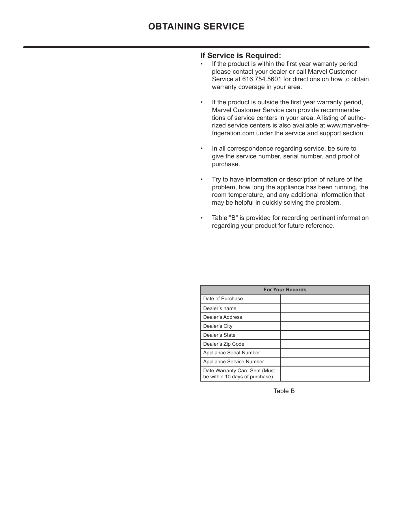
• Table "B" is provided for recording pertinent information
regarding your product for future reference.
For Your Records
Date of Purchase
Dealer’s name
Dealer’s Address
Dealer’s City
Dealer’s State
Dealer’s Zip Code
Appliance Serial Number
Appliance Service Number
Date Warranty Card Sent (Must
be within 10 days of purchase).
Table B
OBTAINING SERVICE
20

MANUAL CONTROL ICEMAKER & COMBO
ROCKER
SWITCH
COND
FAN
WATER
VALVE
SEE COMPRESSOR
DIAGRAMS
BROWN
BLUE
BLUE
WHITE
BLACK
BLACK
WHITE
BIN
SW
NO
NC
C
WATER
SW
NC
NO
C
HOLD
SW
NO
NC
C
CAM
3 RPM
MOTOR
LIMIT
SW
MOLD HEATER
YELLOW
RED
WHITE
BROWN
BLACK
RED
YELLOW
BROWN
BLACK
BROWN
ORANGE
OR BLUE
BLACK
OR BLUE
OR
ALL OTHER MODELS
ICEMAKER
BI1215 ONLY
CONTROL
GROUND:
GREEN or GREEN W/ YELLOW
115
VOLT
PLUG
220-240 VOLT
PLUG
BLACK-HOT
(SMOOTH)
BLACK-NEUTRAL
(RIBBED)
BLACK
WHITE
RED
YELLOW
BROWN
WHITE
BLACK
1
3
6
4
4
1
5
3
2
6
4
1
5
3
2
6
NEUTRAL
H
OT
RELAY
EMBRACO
COMPRESSOR
GREEN or
GREEN W/ YELLOW
GROUND:
OVERLOAD
21
Product Liability
Field se
rvice technicians are authorized to make an initial
assessment in the event of reported damages. If there are
any questions about the process involved, the technician
should call Marvel for further explanation.
While inspecting for defects or installation issues, photos
should be taken to document any damages or issues und.
During the assessment, if the service technician is able to
find the source of the damage and it can be resolved by
replacement of a part, the servicer is authorized to replace
the part in question. The part that caused the damage
must be returned to Marvel in its entirety. The part must
be clearly labeled with the serial number of the unit it was
removed from, the date, and the servicer who removed the
part.
If the service technician determines the damage is the
result of installation issues (water connection/drain, etc.),
the consumer would be notified and the issues shall be
resolved at the direction of the consumer.
If damage is evident and the service technician is
unable to nd the source, Marvel must be contacted at
616.754.5601 for further direction.
1260
E
.
V
an Deinse St•
G
reenville, MI 48838
T: +1.616.754.5601
Website: www.marvelrefrigeration.com
The original refrigeration experts since 1892.
Product Liability
22
Warranty Claims
The following inrmation defines the parameters for ling a
warranty claim:
• Valid serial number needed
• Valid model number needed
• Claims must be submitted online at
www. marvelservice
.
m
• 60 day submittal deadline from date of completed
service
• Only one repair or unit per warranty claim
• Part order numbers will be required when submitting
for warranty labor
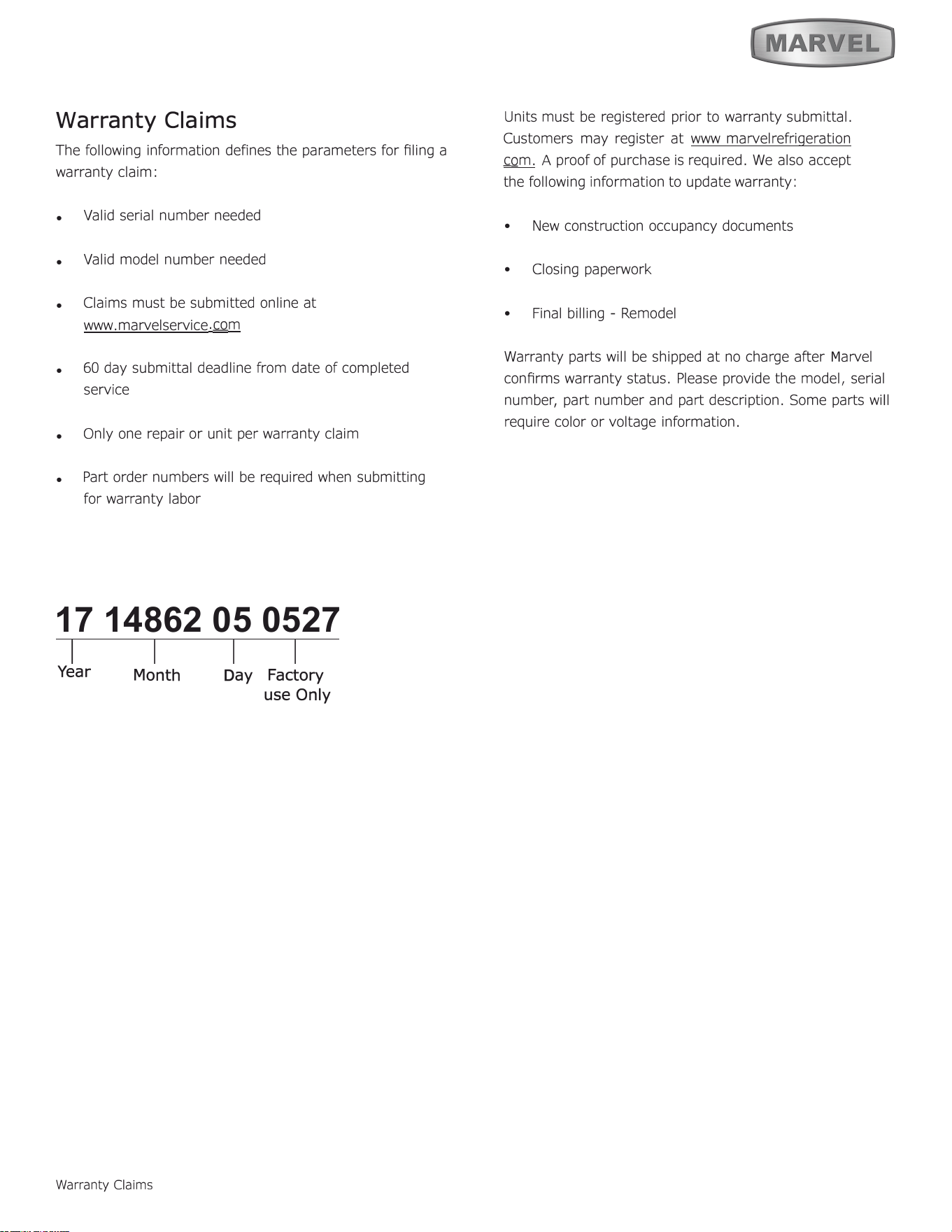
17 14862 05 0527
1
I I I
Year
Warranty Claims
D
ay
Factory
use O
nly
Units must be registered prior to warranty submittal.
Customers may register at www marvelrefrigeration
com. A proof of purchase is required. We also accept
the following information to update warranty:
•
New construction occupancy documents
•
Closing paperwork
•
Final billing - Remodel
Warranty parts will be shipped at no charge aer
M
arvel
conrms warranty status. Please provide the model, serial
number, part number and part description. Some parts will
require color or voltage information.
Month
23
Ordering Replacement Parts
Parts may be ordered online at
partsformarvel.com
O
r contact:
www.marvelrefrigeration.com
(Servicers choose
"
Login
"
for
service account).
Phone Number: (
6
1
6
) 754-5
6
01
NOTICE
Use only genuine
M
arvel replacement parts. The
use of non-
M
arvel parts can reduce performance,
damage the unit, and void the warranty.
Warranty parts will be shipped at no charge after
M
arvel
confirms warranty status. Please provide the model, serial
number, part number and part description. Some parts will
require color or voltage information.
M
arvel requires the return of original parts, we will inform
you when the parts order is taken. This requirement will
be noted on your packing list. A prepaid shipping label will
be emailed to you. Please enclose a copy of the parts
packing list and be sure the model and serial numbers are
legible on the paperwork. Tag the part with the reported
defect.
Customers and non-authorized servicers may order non
warranty parts at www.partsformarvel.com. Authorized
servicers with a servicer login may order non-warranty
parts at www.marvelrefrigeration.m.
Ordering Replacement Parts
24
R-600A Specifications
&
H
an
dl
in
g
RISK Of FIRE OR EXPLOSION. FMMABLE REFRIGENT
USED. TO BE REPAIRED ONLY BY TINED SERVICE
PEONNEL DO HOT PUNURE REFRIGENT TUBING
SK Of FIRE OR EXPLOSION. FMHA_BLE REFRIGENT USED. CONSULT
REPAIR ANUAVOWHER'S GUIDE BEFORE AEMPTING TO SERVICE THIS
PRODU. ALL FE PREUONS HU BE FOUOWEO.
SK Of FIRE OR EXPLOSION. DISPOSE Of PROPER IN ACCORDANCE WITH
FEDE OR LOL REGUTIONS. FHHABLE REFRIGENT USED.
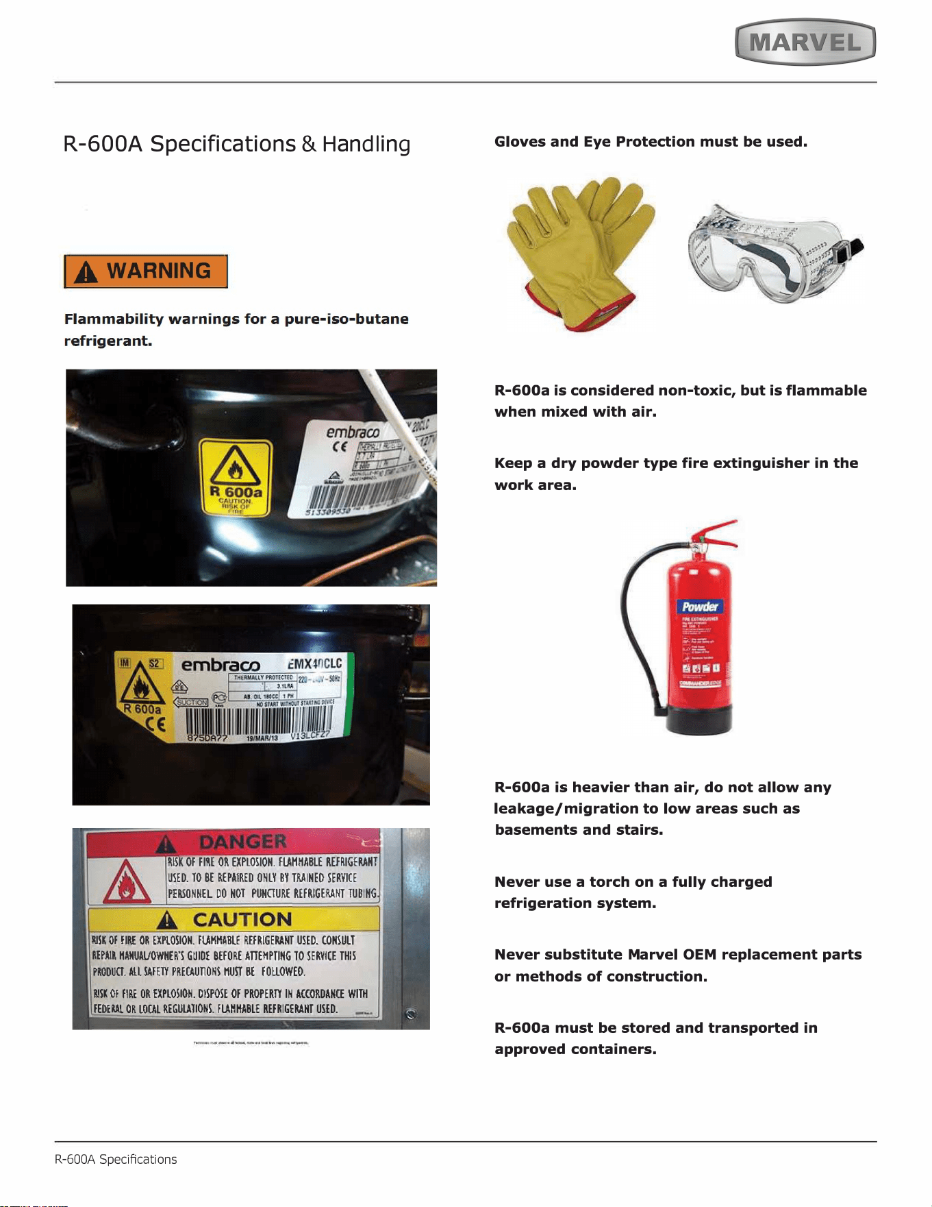
R-600A Specications
Gloves and Eye Protection must be used.
,
. ���·
'
R-600a is considered non-toxic, but is flammable
when mixed with air.
Keep a dry powder type fire extinguisher in the
work area.
R-600a is heavier than air, do not allow any
leakage/migration to low areas such as
basements and stairs.
Never use a torch on a fully charged
refrigeration system.
Never substitute Marvel OEM replacement parts
or methods of construction.
R-600a must be stored and transported in
approved containers.
25
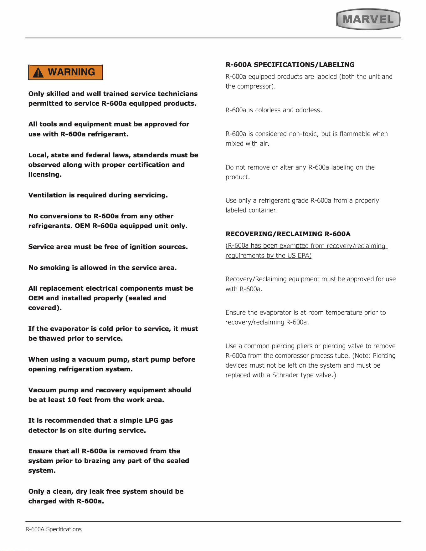
IA WARNING I
Only skilled and well trained service technicians
permitted to service R-600a equipped products.
All tools and equipment must be approved for
use with R-600a refrigerant.
Local, state and federal laws, standards must be
observed along with proper certification and
licensing.
Ventilation is required during servicing.
No conversions to R-600a from any other
refrigerants. OEM R-600a equipped unit only.
Service area must be free of ignition sources.
No smoking is allowed in the service area.
All replacement electrical components must be
OEM and installed properly (sealed and
covered).
If the evaporator is cold prior to service, it must
be thawed prior to service.
When using a vacuum pump, start pump before
opening refrigeration system.
Vacuum pump and recovery equipment should
be at least 10 feet from the work area.
It is recommended that a simple LPG gas
detector is on site during service.
Ensure that all R-600a is removed from the
system prior to brazing any part of the sealed
system.
Only a clean, dry leak free system should be
charged with R-600a.
R-600A Specications
R-600A SPECIFICATIONS/LABELING
R-600a equipped products are labeled (both the unit and
the compressor).
R-600a is colorless and odorless.
R-600a is considered non-toxic, but is flammable when
mixed with air.
Do not remove or alter any R-600a labeling on the
product.
Use only a refrigerant grade R-600a from a properly
labeled container.
RECOVERING/RECLAIMING R-600A
(
R-6
00a
h
as b
e
e
n
exempted from revery/reaiming
requirements by the US EPA)
Recovery/Reclaiming equipment must be approved for use
with R-600a.
Ensure the evaporator is at room temperature prior to
recovery /reclaiming R-600a.
Use a common piercing pliers or piercing valve to remove
R-600a from the compressor process tube. (Note: Piercing
devices must not be le on the system and must be
replaced with a Schrader type valve.)
26
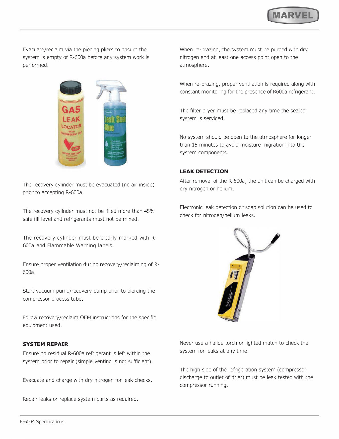
Evacuate/reclaim via the piecing pliers to ensure the
system is empty of R-600a before any system work is
performed.
GAS
LEA
LOCATO
The recovery cylinder must be evacuated (no air inside)
prior to accepting R-600a.
The recovery cylinder must not be filled more than 45%
safe fill level and refrigerants must not be mixed.
The recovery cylinder must be clearly marked with R-
600a and Flammable Warning labels.
Ensure proper ventilation during recovery/reclaiming of R-
600a.
Start vacuum pump/recovery pump prior to piercing the
compressor process tube.
Follow recovery/reclaim OEM instructions for the specific
equipment used.
SYSTEM REPAIR
Ensure no residual R-600a refrigerant is left within the
system prior to repair (simple venting is not sufficient).
Evacuate and charge with dry nitrogen for leak checks.
Repair leaks or replace system parts as required.
R-600A Specications
When re-brazing, the system must be purged with dry
nitrogen and at least one access point open to the
atmosphere.
When re-brazing, proper ventilation is required along with
constant monitoring for the presence of R600a refrigerant.
The filter dryer must be replaced any time the sealed
system is serviced.
No system should be open to the atmosphere for longer
than 15 minutes to avoid moisture migration into the
system components.
LEAK DETECTION
After removal of the R-600a, the unit can be charged with
dry nitrogen or helium.
Electronic leak detection or soap solution can be used to
check for nitrogen/helium leaks.
Never use a halide torch or lighted match to check the
system for leaks at any time.
The high side of the refrigeration system (compressor
discharge to outlet of drier) must be leak tested with the
compressor running.
27
The low side of the refrigeration system (evaporator,
compressor and suction line) must be leak tested with the
compressor off (equalized pressure).
RECHARGING
No air is ever to be allowed inside the refrigeration system
(R-600a refrigerant or dry nitrogen only).
Never use a torch on a fully charged refrigeration system.
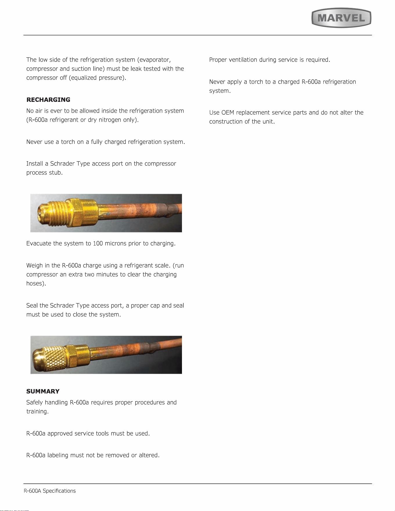
Install a Schrader Type access port on the compressor
process stub.
Evacuate the system to 100 microns prior to charging.
Weigh in the R-600a charge using a refrigerant scale. (run
compressor an extra two minutes to clear the charging
hoses).
Seal the Schrader Type access port, a proper cap and seal
must be used to close the system.
SUMMARY
Safely handling R-600a requires proper procedures and
training.
R-600a approved service tools must be used.
R-600a labeling must not be removed or altered.
R-600A Specications
Proper ventilation during service is required.
Never apply a torch to a charged R-600a refrigeration
system.
Use OEM replacement service parts and do not alter the
construction of the unit.
28
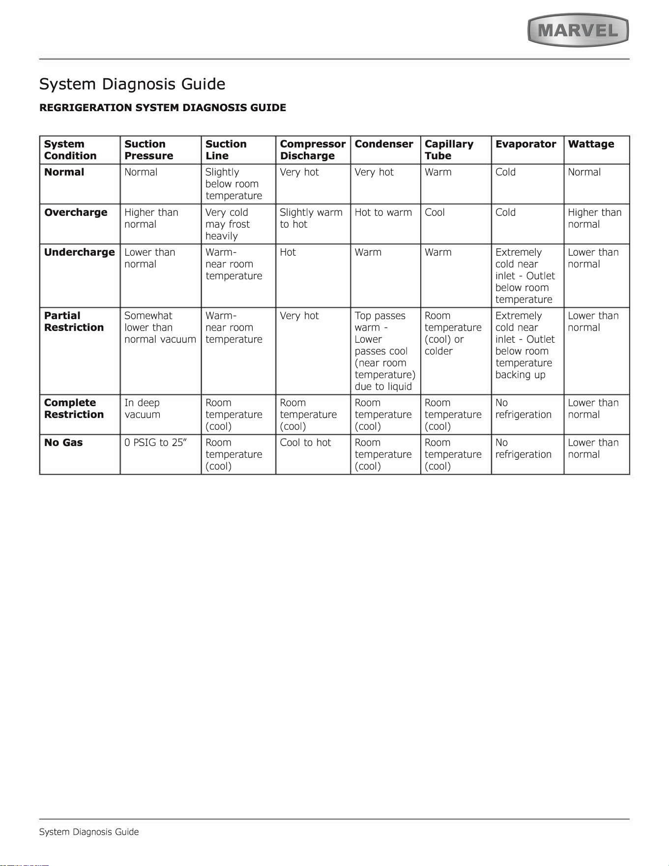
System Diagnosis Guide
REGRIGERATION SYSTEM DIAGNOSIS GUIDE
System
Suction Suction
Compressor
Condition
Pressure
Line
Discharge
Normal Normal Slightly
Very hot
below room
temperature
Overcharge
Higher than
Very cold
Slightly warm
normal
may frost
to hot
heavily
Undercharge
Lower than
Warm- Hot
normal near room
temperature
Partial
Somewhat Warm-
Very hot
Restriction
lower than
near room
normal vacuum
temperature
Complete
In deep
Room Room
Restriction
vacuum
temperature temperature
(cool) (cool)
No Gas
0 PSIG to 25" Room
Cool to hot
temperature
(cool)
System Diagnosis Guide
Condenser
Capillary
Evaporator
Wattage
Tube
Very hot
Warm Cold Normal
Hot to warm
Cool
Cold
Higher than
normal
Warm Warm
Extremely Lower than
cold near
normal
inlet - Outlet
below room
temperature
Top passes
Room
Extremely Lower than
warm -
temperature
cold near
normal
Lower
(cool) or
inlet - Outlet
passes cool
colder
below room
(near room
temperature
temperature)
backing up
due to liquid
Room Room No
Lower than
temperature temperature refrigeration
normal
( cool) (cool)
Room Room No
Lower than
temperature temperature refrigeration
normal
( cool) (cool)
29
Defrost
Defrost
This unit defrosts every 4 hours of compressor runtime for 45 minutes. If you have verified that the unit does
not have an ambient air leak, utilize the Control Operation - Service section and adjust unit to defrost every
3 hours for 60 minutes. Also, adjust the #2 thermistor to -4 instead of 0.
30
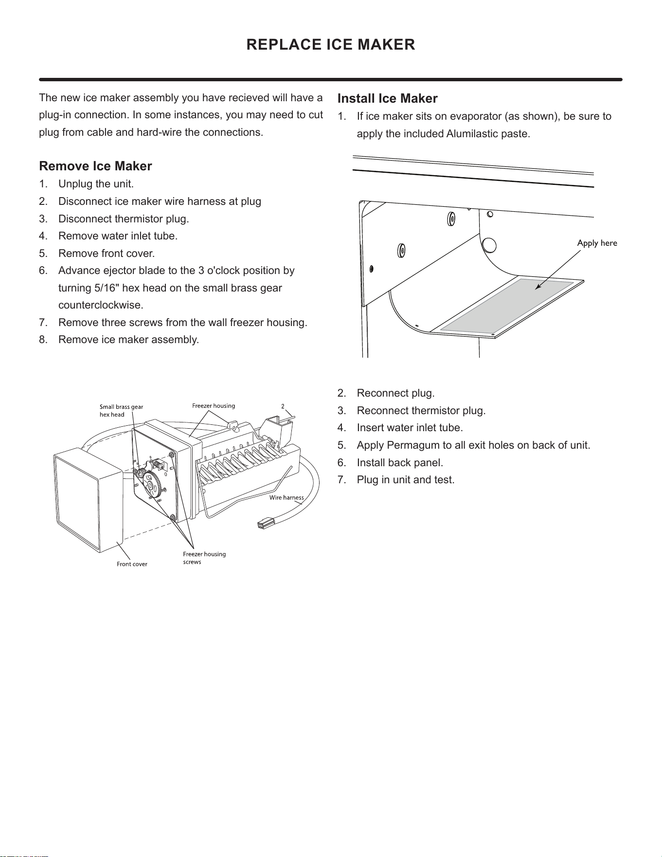
REPLACE ICE MAKER
The new ice maker assembly you have recieved will have a
plug-in connection. In some instances, you may need to cut
plug from cable and hard-wire the connections.
Remove Ice Maker
1. Unplug the unit.
2. Disconnect ice maker wire harness at plug
3. Disconnect thermistor plug.
4. Remove water inlet tube.
5. Remove front cover.
6. Advance ejector blade to the 3 o'clock position by
turning 5/16" hex head on the small brass gear
counterclockwise.
7. Remove three screws from the wall freezer housing.
8. Remove ice maker assembly.
Install Ice Maker
1. If ice maker sits on evaporator (as shown), be sure to
apply the included Alumilastic paste.
2. Reconnect plug.
3. Reconnect thermistor plug.
4. Insert water inlet tube.
5. Apply Permagum to all exit holes on back of unit.
6. Install back panel.
7. Plug in unit and test.
Apply here
31
HOUSEHOLD PRODUCT WARRANTY
Marvel Refrigeration (Marvel) Limited Warranty
ONE YEAR LIMITED PARTS & LABOR WARRANTY
For one year from the date of original purchase, this warranty covers all parts and labor to repair or replace any part of the product that proves to
be defecve in materials or workmanship. For products installed and used for normal residenal use, material cosmec defects are included in this
warranty, with coverage limited to 60 days from the date of original purchase. All service provided by Marvel under the above warranty must be
performed by a Marvel factory authorized servicer, unless otherwise specied by Marvel. Service provided during normal business hours.
TWO YEAR LIMITED PARTS & LABOR WARRANTY (MARVEL PROFESSIONAL PRODUCTS)
For two years from the date of original purchase, this warranty covers all parts and labor to repair or replace any part of the product that proves to
be defecve in materials or workmanship. For products installed and used for normal residenal use, material cosmec defects are included in this
warranty, with coverage limited to 60 days from the date of original purchase. All service provided by Marvel under the above warranty must be
performed by a Marvel factory authorized servicer, unless otherwise specied by Marvel. Service provided during normal business hours.
AVAILABLE THIRD YEAR LIMITED WARRANTY (MARVEL PROFESSIONAL PRODUCTS)
For designated Marvel Professional product, Marvel oers a one year extension of the two year warranty coverage from the date of purchase, free
of charge. To take advantage of this third year warranty, you must register your product with Marvel within 60 days from the date of purchase at
marvelrefrigeration.com and provide proof of purchase. Nugget Ice Machine proof of purchase must include the purchase of an in-line water filter
and filter head to qualify for this additional limited warranty.
LIMITED FIVE YEAR SEALED SYSTEM WARRANTY
For five years from the date of original purchase, Marvel will repair or replace the following parts, labor not included, that prove to be defective in
materials or workmanship: compressor, condenser, evaporator, drier, and all connecting tubing. All service provided by Marvel under the above
warranty must be performed by a Marvel factory authorized servicer, unless otherwise specified by Marvel. Service provided during normal
business hours.
WARRANTY TERMS
These warranties apply only to products installed in any one of the fifty states of the United States, the District of Columbia, or the ten provinces of
Canada. The warranties do not cover any parts or labor to correct any defect caused by negligence, accident or improper use, maintenance, instal-
lation, service, repair, acts of God, fire, flood or other natural disasters. The product must be installed, operated, and maintained in accordance
with the Marvel User Guide.
The remedies described above for each warranty are the only ones that Marvel will provide, either under these warranties or under any warranty
arising by operation of law. Marvel will not be responsible for any consequential or incidental damages arising from the breach of these warranties
or any other warranty, whether express, implied, or statutory. Some states do not allow the exclusion or limitation of incidental or consequential
damages, so the above limitation or exclusion may not apply to you. These warranties give you specific legal rights, and you may also have other
rights which vary from state to state.
Any warranty that may be implied in connection with your purchase or use of the product, including any warranty of merchantability or any war-
ranty fit for a particular purpose is limited to the duration of these warranties, and only extends to five years in duration for the parts described
in the section related to the five year limited warranty above. Some states do not allow limitations on how long an implied warranty lasts, so the
above limitations may not apply to you.
• The warranties only apply to the original purchaser and are non-transferable.
• The second, third, and five year warranties cover products installed and used for normal residential use only.
• The warranties apply to units operated outside only if designed for outdoor use by model and serial number.
• Replacement water filters, light bulbs, and other consumable parts are not covered by these warranties.
• The start of Marvel’s obligation is limited to four years after the shipment date from Marvel.
• In-home instruction on how to use your product is not covered by these warranties.
• Food, beverage, and medicine loss are not covered by these warranties.
• If the product is located in an area where Marvel factory authorized service is not available, you may be responsible for a trip charge or
you may be required to bring the product to a Marvel factory authorized service location at your own cost and expense.
• Units purchased after use as floor displays, and/or certified reconditioned units, are covered by the limited one year warranty only and
no
coverage is provided for cosmetic defects.
• Signal issues related to Wi-Fi connectivity are not covered by these warranties.
For parts and service assistance, or to nd Marvel factory authorized service near you, contact Marvel Refrigeraon:
MarvelRefrigeraon.com • techsupport@MarvelRefrigeraon.com • +616.754.5601
1260 E. Van Deinse St., Greenville, MI 48838
32
All specications and product designs subject to change without notice. Such revisions do not entitle
the buyer to corresponding changes, improvements, additions, replacements or compensation for
previously purchased products.
www.marvelrefrigeration.com
Marvel Refrigeration
1260 E. Van Deinse St.
Greenville MI 48838
616.754.5601
33