Loading ...
Loading ...
Loading ...

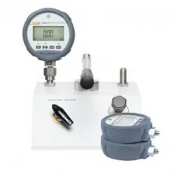
Pneumatic Comparison Test Pump
Maintenance and Servicing
7
1. Ensure exhaust valve is closed — Do not over tighten, as damage to the valve seat
can occur.
2. To generate a vacuum in the system, use the handpump until the desired reading is
reached.
3. Allow a few moments for the system to stabilize before taking any readings,
especially after large changes in system pressure.
Note
Large, sudden changes in pressure will cause the system temperature to
rise or fall, which can cause instrument readings to change as the gas in
the system expands or contracts, thus increasing or decreasing the pressure.
4. For the next, higher vacuum point; repeat from 2 above.
5. For lower points, slowly open and close exhaust valve, allowing air into the system.
6. After calibration, always equalize the system pressure by slowly opening the exhaust
valve.
Pressure
1. Ensure exhaust valve is closed — Do not over tighten, as damage to the valve seat
can occur.
2. To increase the system pressure, use the handpump until the desired pressure is
reached.
3. Allow a few moments for the system to stabilize before taking any readings,
especially after large changes in system pressure.
Note
Large, sudden changes in pressure will cause the system temperature to
rise or fall, which can cause instrument readings to change as the gas in
the system expands or contracts, thus increasing or decreasing the pressure.
4. For the next, higher pressure point, repeat from 2 above.
5. To reduce system pressure, slowly open and close exhaust valve until the desired
pressure is reached.
6. Before taking any readings, allow a few moments for the system to stabilize as before.
7. After calibration, always vent system pressure by slowly opening the exhaust valve.
During operation, air is drawn into the pump assembly through the upper port in the
pump cylinder (13) when the piston is lifted, and expelled through the lower port when
the piston is pushed down.
Maintenance and Servicing
The part number for the replacement seal kit is P5510SK.
Contamination
W Caution
If the system becomes contaminated with dirt or moisture the
instrument must be disassembled and cleaned, otherwise the
pump may become damaged beyond repair.
Pump Removal
1. Remove unit from bench such that it can be turned over.
1.888.610.7664 sales@GlobalTestSupply.com
Fluke-Direct.com
Loading ...
Loading ...
Loading ...