Loading ...
Loading ...

4
5
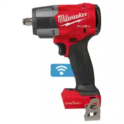
1/2" Impact Wrench with Pin Detent
(Cat. No. 3062P-20)
1. WARNING! Remove battery to avoid starting the tool.
2. Use only the appropriate size square drive sockets.
3. To attach a socket, align the hole in the accessory
with the detent pin on the anvil. Hold the detent
pin in while pushing the socket onto the anvil.
The detent pin will snap into place in the hole to
secure the socket.
4. To remove the socket, insert a nail or other thin
object into the hole in the accessory and press
in the detent pin. Pull the accessory o the anvil.
ONE-KEY™
To learn more about the ONE-KEY™ functionality
for this tool, go to milwaukeetool.com/One-Key. To
download the ONE-KEY™ app, visit the App Store
®
or Google Play™ from your smart device.
ONE-KEY™ Indicator
Solid Blue Wireless mode is active and ready
to be congured via the ONE-KEY™
app.
Blinking Blue Tool is actively communicating with
the ONE-KEY™ app.
Blinking Red Tool is in security lockout and can
be unlocked by the owner via the
ONE-KEY™ app.
OPERATION
WARNING
To reduce the risk of injury, always
wear proper eye protection marked
to comply with ANSI Z87.1.
When working in dusty situations, wear appro-
priate respiratory protection or use an OSHA
compliant dust extraction solution.
Using the Drive Control
The drive control button is used to adjust the torque,
rotation speed (RPM), and impact speed (IPM) for
the application.
To select the drive control mode:
Drive Control Button
Mode Indicator
ONE-KEY™
1. Pull and release the trigger
to turn on the tool. The cur-
rent mode indicator is lit.
2. Press the drive control but-
ton to cycle through the
modes. Select wireless
to change the default set-
tings via the ONE-KEY™
App on your smart device.
When the desired mode indicator is lit, begin work.
NOTE: Select the torque range in accordance with
the equipment manufacturers fastening instruc-
tions. For precision applications, conrm the nal
tightening torque with a calibrated device.
Using the Control Switch
The control switch may be set to three positions:
forward, reverse and lock. Due to a lockout mecha-
nism, the control switch can only be adjusted when
the ON/OFF switch is not pressed. Always allow the
motor to come to a complete stop before using the
control switch.
For forward (clockwise) rotation, push in the control
switch from the right side of the tool. Check the
direction of rotation before use.
For reverse (counterclockwise) rotation, push in the
control switch from the left side of the tool. Check
direction of rotation before use.
To lock the trigger, push the control switch to the
center position. The trigger will not work while the
control switch is in the center locked position. Always
lock the trigger or remove the battery pack before
performing maintenance, changing accessories,
storing the tool and any time the tool is not in use.
Direction Lock
Use the direction lock feature via the ONE-KEY™ app
to restrict the tool direction to either FORWARD or
REVERSE.
Control switch
in forward
Control switch
in reverse
ONE-KEY™
Direction
Lock set to
FORWARD
Tool will run in
forward only
Tool will not
run, LED
performance
indicator will light
ONE-KEY™
Direction
Lock set to
REVERSE
Tool will not
run, LED
performance
indicator will light
Tool will run in
reverse only
ONE-KEY™
Direction
Lock set to
OFF
Tool will run in
forward
Tool will run in
reverse
Selecting Speed
Mode RPM IPM
1 0 - 1400 0 - 1800
2 0 - 1725 0 - 2300
3 0 - 2000 0 - 2800
4 0 - 2400 0 - 3400
Allow the tool to come to a complete stop before
changing speeds. Press the selector button to
cycle between the settings.
FUNCTIONAL DESCRIPTION
1. 1/2" friction ring (3062-20)
2. LED performance indicator
3. Handle
4. Lanyard loop (3062P-20)
5. Drive control button
6. Trigger
7. Control switch
8. LED
9. 1/2" pin detent (3062P-20)
1
7
5
8
6
9
3
2
4
ASSEMBLY
WARNING
Recharge only with the charger
specied for the battery. For spe-
cic charging instructions, read the operator’s
manual supplied with your charger and battery.
Removing/Inserting the Battery
To remove the battery, push in the release buttons
and pull the battery pack away from the tool.
WARNING
Always remove the battery pack
any time the tool is not in use.
To insert the battery, slide the pack into the body
of the tool. Make sure it latches securely into place.
WARNING
Only use accessories specically
recommended for this tool. Others
may be hazardous.
Use only sockets and other accessories speci-
cally designed for use on impact wrenches and
drivers. Other sockets and accessories might
shatter or break causing injury.
Attaching and Removing Accessories
1/2" Impact Wrench with Friction Ring
(Cat. No. 3062-20)
1. WARNING! Remove battery to avoid starting the tool.
2. Use only the appropriate size square drive sockets.
3. To attach a socket, align the accessory with the
anvil and push it rmly over the retaining ring.
4. To remove the accessory, pull the accessory o
the anvil.
ONE-KEY™ Enabled Modes
WARNING
Scan the QR code below and read
all instructions, illustrations, and
specications for each of the enabled modes for
this tool. Use the proper tool mode and mode
settings in the ONE-KEY™ app for the intended
application. Property damage, ooding, break-
age, or other damage or failure can occur if the
mode's instructions are not properly followed.
Read all safety warnings, instructions, illustra-
tions and specications supplied with the parts,
accessories, fixture, attachment, etc. Only
use with approved items as designated in the
ONE-KEY™ app.
Always conrm the nal tightening torque with a
calibrated torque tool when precision fastening
is required.
Scan this QR code to access Operation
instructions and the most up to date
product use information.
To signify that the tool may be out of
an acceptable performance tolerance,
the LED performance indicators will ash. Refer to
the trouble shooting section in the ONE-KEY™ app.
The tool will still operate, but may not be delivering
the desired output.
Starting, Stopping and Controlling Speed
1. To start the tool, grasp the handle(s) rmly and
pull the trigger.
NOTE: An LED is turned on when the trigger is
pulled and will go o shortly after the trigger is
released.
2. To vary the speed, increase or decrease the pres-
sure on the trigger. The further the trigger is pulled,
the greater the speed.
3. To stop the tool, release the trigger. Ensure the
tool has come to a complete stop before laying
the tool down.
Impacting Techniques
The longer a bolt, screw, or nut is impacted, the
tighter it will become. To help prevent damaging the
fasteners or workpieces, avoid excessive impact-
ing. Be particularly careful when impacting smaller
fasteners because they require less impacting to
reach optimum torque.
Practice with various fasteners, noting the length of
time required to reach the desired torque. Check the
tightness with a hand-torque wrench. If the fasteners
are too tight, reduce the impacting time. If they are
not tight enough, increase the impacting time.
Oil, dirt, rust or other matter on the threads or under the
head of the fastener aects the degree of tightness.
The torque required to loosen a fastener averages
75% to 80% of the tightening torque, depending on
the condition of the contacting surfaces.
On light gasket jobs, run each fastener down to a
relatively light torque and use a hand torque wrench
for nal tightening.
Loading ...
Loading ...
Loading ...