Loading ...
Loading ...
Loading ...
www.PyleUSA.com www.PyleUSA.com
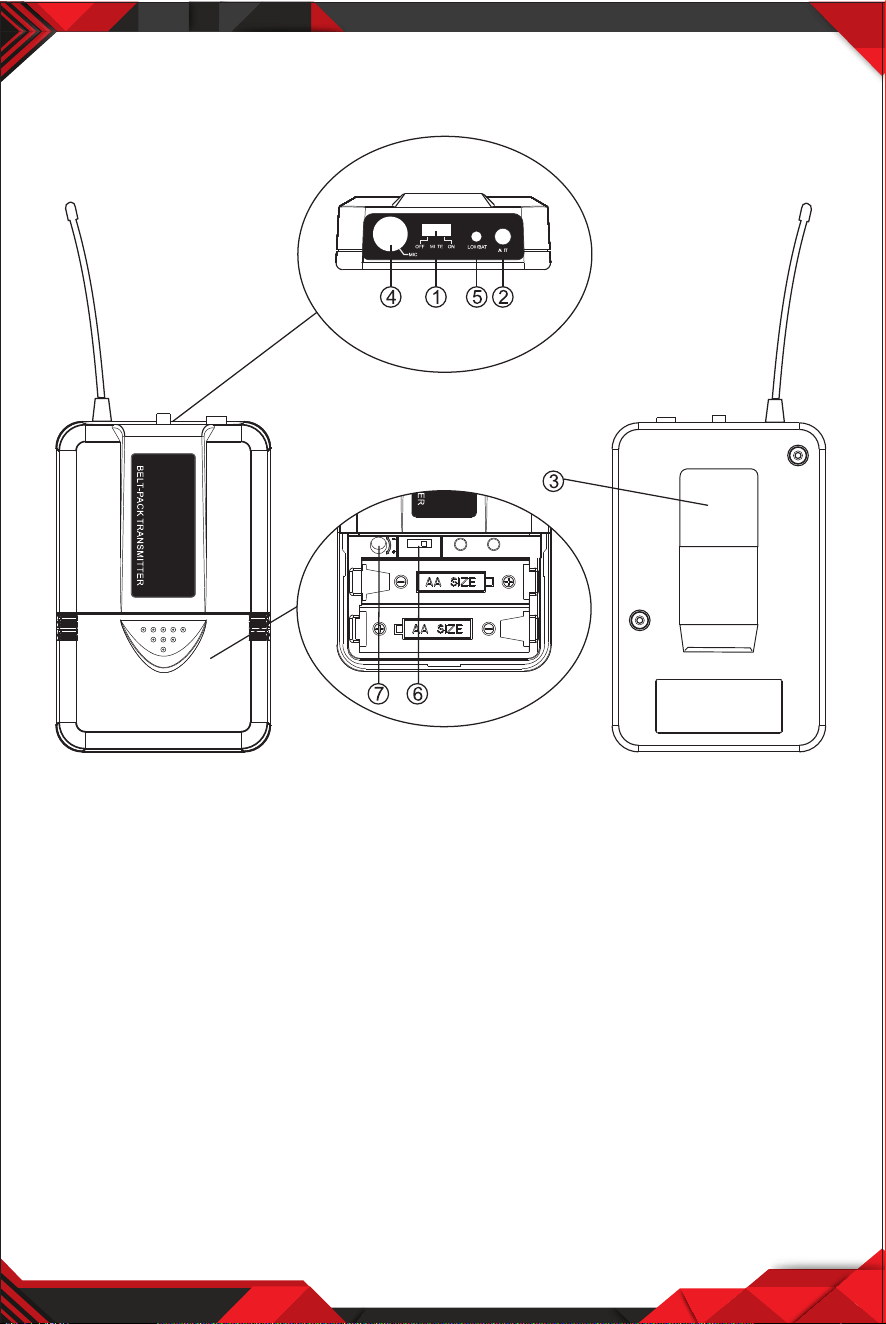
The audio gain control on transmitter has been factory-at the mid-range
position for best performance in most applications. This may be necessary
for soft singers or talkers, or guitar or basses with low outputs.
• To Increase Gain: Rotate the transmitter gain control clockwise using a
screwdriver to increase audio gain.
• To Reduce Gain: Rotate the transmitter gain control counterclockwise with
the screwdriver to reduce audio gain.
• To return audio gain to the factory setting, rotate the transmitter audio
gain control to the mid position.
TIPS FOR ACHIEVING MAXIMUM PERFORMANCE
• Make sure you can always see a receiver antenna from the transmitter
position.
• Keep the distance from transmitter to receiver antenna as short as possible.
• Point receiver antennas away from each other at a 45 angle from vertical.
• Avoid placing the receiver antennas near metal surfaces and obstruction.
• If stacking or rack mounting receivers in a multiple-system use situation, do
not allow antennas to touch or cross.
• Perform a walk-through before Performance or Presentation. If dead spots are
found, adjust location of receiver. If dead spots remain, mark spots and avoid.
9 10
TROUBLESHOOTING
PROBLEM INDICATOR STATUS SOLUTION
No Sound
No Sound
No Sound
No Sound
No Sound
Sound level diers from
the level of a cabled
Instrument.
Sound level diers from
the level of dierent
guitars
Distortion level increases
gradually
Bursts of noise or other
audible radio signals
present
Momentary loss of
sound as transmitter is
moved around
performing area.
Receiver signal indicators
A/B lights glowing
Receiver signal indicators
A/E lights glowing
Signal indicators A/B
lights ON
Receiver signal
indicator A/B lights OFF
when sound is lost
Red transmitter
indicator is not
ashing
Red receiver POWER
light o
Receiver signal
indicators A/B lights
o. Transmitter and
receiver POWER lights
glowing
Receiver signal
indicators A/B lights
glowing
Red transmitter
indicator is ashing
Slide transmitter POWER ON/OFF switch
to ON position. Make sure battery is
inserted properly, observing battery (+/-).
If the battery is inserted properly, replace
with fresh battery.
Slide transmitter MUTE/ON switch to ON
position
Make sure AC adapter is securely
plugged into electrical outlet and into DC
input connector. Make sure AC electrical
outlet works and supplies proper voltage
Trun up receiver volume control. Conrm
that the output connections from the
receiver to the external equipment are
secure
Conrm transmitter and receiver~
frequency match. Move transmitter
closer to receiver.
Adjust transmitter gain level to
compensate.
Adjust receiver volume as necessary
Readjust transmittergain level to
compensate dierences in guitar outputs
Replace transmitter battery
Identify potential sources of interference
(other RF sources) and turn OFF, remove
or use a wireless system operating on a
dierent frequency
Reposition receiver and perform
walk-through again. If audio dropouts
persist, mark “dead” spot-and avoid them
during performance.
Receiver signal indicators
A/B lights and
transmitter LOW
BATTERY light glowing
Loading ...
Loading ...
Loading ...