Please read this manual carefully before operating
your set and retain it for future reference.
General
Multi-Inverter Type
P/NO : MFL68280204
SERVICE MANUAL
AIR
CONDITIONER

- 2 -
Copyright ©2017 LG Electronics. Inc. All right reserved.
Only for training and service purposes
LGE Internal Use Only
Air Conditioner Service Manual
TABLE OF CONTENTS
Part 1 General Information ..........................................................................................................3
1. Safety Precautions........................................................................................................4
2. Model Line Up................................................................................................................7
3. Nomenclature ..............................................................................................................10
Part 2 Functions & Controls......................................................................................................14
1. List of Functions & Accessory ..................................................................................15
2. Air Flow .......................................................................................................................17
3. Air Purifying.................................................................................................................19
4. Installation Functions.................................................................................................20
5. Reliability .....................................................................................................................21
6. Convenience Functions & Controls .........................................................................22
7. Special Function & KIT...............................................................................................29
Part 3 Basic Control ..................................................................................................................32
1. Normal operation ........................................................................................................33
2 Compressor control ....................................................................................................33
3. EEV( Electronic Expansion Valve) control ..............................................................33
4. Oil return control ........................................................................................................34
5. Defrost control ...........................................................................................................34
6. Protection control ......................................................................................................35
Part 4 Test Run..........................................................................................................................36
1. Check before Test Run .............................................................................................37
2. Test Run Flow chart ..................................................................................................38
3. Test Runing.................................................................................................................39
Part 5 Trouble Shooting Guide ...............................................................................................41
1. Self-diagnosis Function .....................................................................................42
2. Pump Down .........................................................................................................44
3. Evacuation...........................................................................................................45
4. Gas Charging ......................................................................................................46
5. Cycle Part ............................................................................................................47
6. Electronic Parts...................................................................................................48

Part 1 General Information
- 3 -
Copyright ©2017 LG Electronics. Inc. All right reserved.
Only for training and service purposes
LGE Internal Use Only
1. Safety Precautions ............................................................................................................4
2. Model Line Up .....................................................................................................................7
3. Nomenclature....................................................................................................................10
Part 1 General Information
Part 1 General Information
- 4 -
Copyright ©2017 LG Electronics. Inc. All right reserved.
Only for training and service purposes
LGE Internal Use Only
1. Safety Precautions
1.1 Cautions in Repair
To prevent injury to the user or other people and property damage, the following instructions must be followed.
n Incorrect operation due to ignoring instruction will cause harm or damage. The seriousness is classified by the follow-
ing indications.
This symbol indicates the possibility of death or serious injury.
This symbol indicates the possibility of injury or damage to properties only.
n Meanings of symbols used in this manual are as shown below.
Be sure to disconnect all remote electric power supplies before servicing. Internal
components and circuit boards are at main potential when the equipment is con-
nected to the power cables. This voltage is extremely dangerous and may cause
death or severe injury if come in contact with it.
Do not touch the discharging refrigerant gas during the repair work.
The refrigerant gas can cause frostbite.
Release the refrigerant gas completely at a well-ventilated place first.
Otherwise, when the pipe is disconnected, refrigerant gas or refrigerating machine
oil discharges and it can cause injury.
When the refrigerant gas leaks during work, execute ventilation. If the refrigerant
gas touches to a fire, poisonous gas generates. A case of leakage of the refriger-
ant and the closed room full with gas is dangerous because a shortage of oxygen
occurs. Be sure to execute ventilation.
When removing the front panel or cabinet, execute short-circuit and discharge
between high voltage capacitor terminals. If discharge is not executed, an electric
shock is caused by high voltage resulted in a death or injury.
Be sure to provide the grounding when repairing the equipment in a humid or wet
place, to avoid electrical shocks.
Be sure not to do.
Be sure to follow the instruction.
Dangerous Voltage
Be sure to provide grounding.
Part 1 General Information
- 5 -
Copyright ©2017 LG Electronics. Inc. All right reserved.
Only for training and service purposes
LGE Internal Use Only
Do not use a defective or underrated circuit breaker. Use the correctly rated
breaker and fuse. Otherwise there is a risk of fire or electric shock.
Install the panel and the cover of control box securely. Otherwise there is risk of
fire or electric shock due to dust, water etc.
Indoor/outdoor wiring connections must be secured tightly and the cable should be
routed properly so that there is no force pulling the cable from the connection ter-
minals. Improper or loose connections can cause heat generation or fire.
Do not touch, operate, or repaire the product with wet hands. Hoding the plug by
hand when taking out. Otherwise there is risk of electric shock or fire.
Use a vacuum pump or Inert (nitrogen) gas when doing leakage test or air purge.
Do not compress air or Oxygen and Do not use Flammable gases. Otherwise, it
may cause fire or explosion.
- There is the risk of death, injury, fire or explosion.
Do not turn on the breaker or power under condition that front panel, cabinet, top
cover, control box cover are removed or opened.
- Otherwise, it may cause fire, electric shock, explosion or death.
Be sure to earth the air conditioner with an earthing conductor connected to the
earthing terminal.
Conduct repair works after checking that the refrigerating cycle section has cooled
down sufficiently. Otherwise, working on the unit, the hot refrigerating cycle section
can cause burns.
Do not tilt the unit when removing panels. Otherwise, the water inside the unit can
spill and wet floor.
Do not use the welder in a well-ventilated place. Using the welder in an enclosed
room can cause oxygen deficiency.
Be sure to turn off power switch before connect or disconnect connector, or parts
damage may be occurred.
Part 1 General Information
- 6 -
Copyright ©2017 LG Electronics. Inc. All right reserved.
Only for training and service purposes
LGE Internal Use Only
1.2 Inspections after Repair
Check to see if the parts are mounted correctly and wires are connected. Im-
proper installation and connections can cause an electric shock or an injury.
Check the installation platform or frame has corroded. Corroded installation plat-
form or frame can cause the unit to fall, resulting in injury.
Be sure to check the earth wire is correctly connected.
After the work has finished, be sure to do an insulation tset to check the resist-
ance is 2[Mohm] or more between the charge section and the non-charge metal
section (Earth position). If the resistance value is low, a disaster such as a leak or
electric shock is caused at user’s side.
Check the drainage of the indoor unit after the repair. If drainage is faulty the
water to enter the room and wet floor.
Check to see if the power cable plug is not dirty or loose. If the plug is dust or
loose it can cause an electrical shock or fire.
Do not use a joined power cable or extension cable, or share the same power
outlet with other electrical appliances. otherwise, it can cause an electrical shock,
excessive heat generation or fire.
Do not insert hands or other objects through the air inlet or outlet while the prod-
uct is operating. There are sharp and moving parts that could cause personal in-
jury.
Do not block the inlet or outlet of air flow. It may cause product failure
Part 1 General Information
- 7 -
Copyright ©2017 LG Electronics. Inc. All right reserved.
Only for training and service purposes
LGE Internal Use Only
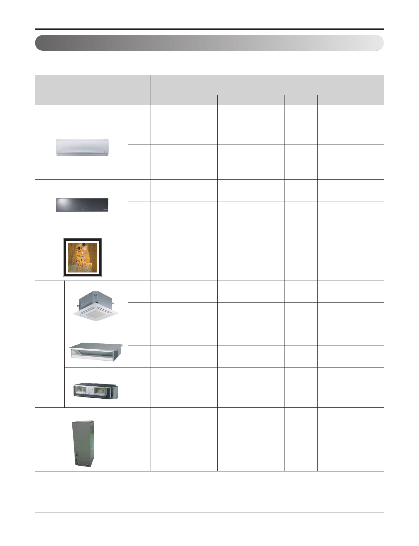
2. Model Line Up
2.1 Indoor units
* Indicates color of panel – ART COOL : Gold(G), White Silver(H), Blue(B), Gallery(1)
ART COOL Mirror : Mirror(R), Silver(V), White(W)
Category
Chassis
Model names
Capacity, kW(kBtu/h Class)
2.1(7) 2.6 (9) 3.5 (12) 4.2(15) 5.3 (18) 7.03 (24) 10.6 (36)
Wall mounted
SB
AMNW07GDBB0
[LMN078HVT]
ASNW09GB1B0
[LSN090HSV4]
ASNW12GB1B0
[LSN120HSV4]
AMNW15GDBB0
[LMN158HVT]
SC
ASNW18GC2B0
[LSN180HSV4]
AMNW24GDCB0
[LMN248HVT]
ART COOL Mirror
SB
ASNW09GBRB0
[LAN090HSV4]
ASNW12GBRB0
[LAN120HSV4]
SC
ASNW18GCRB0
[LAN180HSV4]
ART COOL Gallery
SF
AMNW09GAF11
[LMAN097HVP]
AMNW12GAF11
[LMAN127HVP]
Ceiling
cassette
4-way
TR
AMNW07GTRA0
[LMCN077HV]
AMNW09GTRA0
[LMCN097HV]
AMNW12GTRA0
[LMCN125HV]
TQ
AMNW18GTQA0
[LMCN185HV]
Ceiling
concealed
duct
Low static pressure
(Slim)
L1
AMNW09GL1A0
[LMDN096HV]
L2
AMNW12GL2A0
[LMDN126HV]
AMNW18GL2A0
[LMDN186HV]
High Static pressure
BG
AMNW24GBGA0
[LMHN240HV]
AMNW36GBGA0
[LMHN360HV]
Vertical AHU
NJ
AMNW24GNJA0
[LMVN240HV]
AMNW36GNJA0
[LMVN360HV]
Part 1 General Information
- 8 -
Copyright ©2017 LG Electronics. Inc. All right reserved.
Only for training and service purposes
LGE Internal Use Only
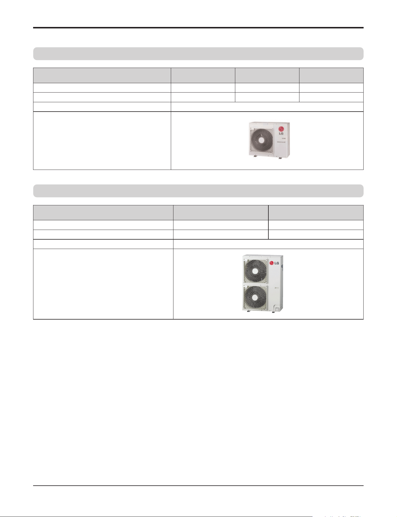
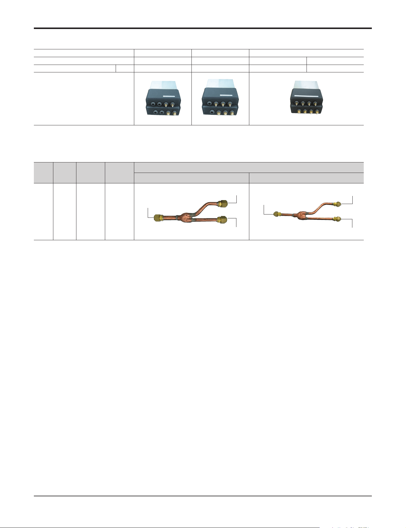
2.2 Outdoor units
Multiple Piping Type
Branch Distribution type
Model Name
A2UW18GFH0
[LMU180HHV]
A3UW24GFH0
[LMU240HHV]
A4UW30GFH0
[LMU300HHV]
No. of connectable indoor units (Min. ~ Max.)
2 ~ 2 2 ~ 3 2 ~ 4
Total capacity index of connectable indoor units
24 33 40
Power supply 208/230V, 1Ø, 60Hz
Chassis
Model Name
A5UW36GFH0[LMU360HHV] A6UW42GFH0[LMU420HHV]
No. of connectable indoor units (Min. ~ Max.)
2 ~ 5 2 ~ 6
Total capacity index of connectable indoor units
48 56
Power supply
208/230V, 1Ø, 60Hz
Chassis
Part 1 General Information
- 9 -
Copyright ©2017 LG Electronics. Inc. All right reserved.
Only for training and service purposes
LGE Internal Use Only
2.3 BD(Branch distributor) units
2.4 Branches
Branch
Type
No. of
BD
Units
Accessory
Model Name
Applicable
Model
Specifications
Gas Liquid
Y-
Branch
2
PMBL5620
MULTI F MAX
To BD unit Ø19.05 (3/4)
Ø19.05 (3/4)
To ODU
Ø19.05 (3/4)
To BD unit Ø9.52 (3/8)
Ø9.52 (3/8)
To ODU
Ø9.52 (3/8)
No. of connectable indoor units(Min. ~ Max.)
1 ~ 2 1 ~ 3 1 ~ 4
Model name PMBD3620 PMBD3630 PMBD3640 PMBD3641
Connectable indoor unit capacity kBtu/h 9 ~ 24 9 ~ 24 9 ~ 24 9 ~ 36
BD unit
Part 1 General Information
- 10 -
Copyright ©2017 LG Electronics. Inc. All right reserved.
Only for training and service purposes
LGE Internal Use Only
3. Nomenclature
3.1 Indoor Unit(Global)
AMN W G07 BDL0
Serial number
Indicates that this is multi system indoor unit using R410A
Model type
W : DC Inverter heat pump
Ex) 7,000 Btu/h Class
→ '07', 18,000 Btu/h Class → '18'
Cooling/heating capacity
Electrical rating
G : 1Φ, 208~230V, 60Hz
Chassis naem(Only Multi)
Indoor unit type(Only Multi)
A : ART COOL Gallery
D : Wall Mounted, ART COOL Mirror
T : Ceiling cassette, B : Ceiling concealed duct
N : Vertical AHU
Function
A : Basic, L : Plasma (Wall mounted)
C : Plasma(ceiling cassette)
Front panel design/color of ART COOL type
R : Mirror, 1 : Gallery
Part 1 General Information
- 11 -
Copyright ©2017 LG Electronics. Inc. All right reserved.
Only for training and service purposes
LGE Internal Use Only
Code Type Code of Model Meaning
1 Production Center, A~Z L: Chang-won R22
Refrigerant A: Chang-won R410A
2 Product Type A~Z S: Split Type Air Conditioner
3 Cooling/Heating/Inverter A~Z C: Cooling Only
H: Heat Pump
X: C/O + E/Heater
Z: H/P + E/Heater
V: AC Inverter C/O
N: AC Inverter H/P
Q: DC Inverter C/O
W: DC Inverter H/P
4, 5 Capacity 0~9 Cooling/Heating Capacity
Ex. "09" ’ 9,000 Btu/h Class
6 Electric Range 1~9 1: 115V/60Hz
A~Z 2: 220V/60Hz
3: 208-230V/60Hz
5: 200-220V/50Hz
6: 220-240V/50Hz
7: 110V, 50/60Hz
7 Chassis A~Z Name of Chassis
8 Look A~Z Look,
Color (Artcool Model)
9 Function A~Z
10 Serial No. 1~9 LG Model Development Serial No.
12 - 345678910
Basic A
Basic+4Way B
Basic+Deodorizing Filter (Carbon filter) C
Plasma+(A/changeove)+A/clean+2Way+Ion E
Plasma+(A/changeove)+A/clean+4way+Ion+Lamp F
Plasma+(A/changeove)+A/clean+Low A G
Plasma+(A/changeove)+A/clean+4way+Low A H
Plasma+(A/changeove)+A/clean L
Plasma+(A/changeove)+A/clean+4way M
Plasma+(A/changeove)+A/clean+PTC N
Plasma+(A/changeove)+Autoclean+4way+PTC P
Plasma+(A/changeove)+A/clean+4way+Low A+PTC Q
Smart(Robot) Cleaning R
Eco eye+Plasma+Allergy Filter+4way S
Plasma+Allergy Filter+4way U
Allergy Filter+4way V
Allergy Filter+2way W
Basic+Low Ambient Y
Basic+(A/clean)+4way+Low A Z
A S - W 1 2 6 B M S 0
Part 1 General Information
- 12 -
Copyright ©2017 LG Electronics. Inc. All right reserved.
Only for training and service purposes
LGE Internal Use Only
A4U W G30 F H 0
Electrical rating
Indicates that this is multi system outdoor unit using R410A
Ex) A4U : Connectable max. 4 indoor units
A6U : Connectable max. 6 indoor units
Model type
W : DC inverter heat pump
Ex) 24,000 Btu/h Class
→ ‘24’, 42,000 Btu/h Class → ‘42’
Cooling/heating capacity
G : 1Φ, 208~230V, 60Hz
Multi type
Function
A : Basic
H : High Heat
F : Free joint multi type
Serial number
3.2 Outdoor Unit(Global)
Part 1 General Information
- 13 -
Copyright ©2017 LG Electronics. Inc. All right reserved.
Only for training and service purposes
LGE Internal Use Only
P M BD 36 2 0
Serial number
Number of connectable indoor units
Max. capacity of connectable indoor units
“36” mean that 7~36kBtu/h Class Indoor unit connected to BD unit
BD : Branch distributor
M : Multi system outdoor unit
P : Parts
3.3 BD units(Global)

Part 2 Functions & Controls
- 14 -
Copyright ©2017 LG Electronics. Inc. All right reserved.
Only for training and service purposes
LGE Internal Use Only
Part 2 Functions & Controls
1. List of Functions & Accessory......................................................................................15
2. Air flow ............................................................................................................................17
2.1 Auto swing (left & right) ...............................................................................................17
2.2 Auto swing (up & down) ..............................................................................................17
2.3 Chaos swing (up/down)...............................................................................................17
2.4 Air flow step.................................................................................................................18
2.5 Chaos wind (auto wind)...............................................................................................18
2.6 Jet Cool Mode Operation ............................................................................................18
2.7 Swirl wind Swing .........................................................................................................18
3. Air purifying ....................................................................................................................19
3.1 PLASMA Air Purifying System.....................................................................................19
4. Installation Functions ....................................................................................................20
4.1 E.S.P. (External Static Pressure) Setting ....................................................................20
5. Reliability ........................................................................................................................21
5.1 Hot start.......................................................................................................................21
5.2 Self-diagnosis Function...............................................................................................21
5.3 Soft dry operation........................................................................................................21
6. Convenience Functions & Controls ............................................................................22
6.1 Cooling & heating Operations ....................................................................................22
6.2 Auto cleaning operation...............................................................................................23
6.3 Auto Operation (Artificial Intelligence) .........................................................................23
6.4 Auto restart Opeartion .................................................................................................24
6.5 Child Lock Function.....................................................................................................25
6.6 Forced operation.........................................................................................................25
6.7 Group Control..............................................................................................................26
6.8 Sleep Timer Operation ................................................................................................27
6.9 Timer(On/Off) ..............................................................................................................27
6.10 Weekly Program........................................................................................................27
6.11 Two Thermistor Control .............................................................................................28
7. Special Function & KIT ..................................................................................................29
7.1 Low Ambient control....................................................................................................29
7.2 Space Control .............................................................................................................29
7.3 Auto Elevation Grille....................................................................................................29
7.4 Defrost Control(Heating) .............................................................................................31
Part 2 Functions & Controls
- 15 -
Copyright ©2017 LG Electronics. Inc. All right reserved.
Only for training and service purposes
LGE Internal Use Only
[Note]
O : Applied, X : Not applied
Accessory model name : Installed at field, ordered and purchased separately by the corresponding model name, sup-
plied with separate package.
1. List of Functions & Accessory
1.1 List of Functions
• Indoor
Category Functions
Wall Mounted ART COOL Mirror
ART COOL
Gallery
Ceiling cassette
4-way
Ceiling concealed
duct (Low static
pressure)
Ceiling concealed
duct (High static
pressure)
Vertical Air Han-
dling Unit
Air flow
Air supply outlet
1 1 3 4 1 1 1
Airflow direction control (left & right)
Auto Auto Auto X X X X
Airflow direction control (up & down)
Auto Auto Auto Auto X X X
Auto swing (left & right)
O O O X X X X
Auto swing (up & down)
O O O O X X X
Airflow steps (fan/cool/heat)
6 / 6 / 6 6 / 6 / 6 5 / 5 / 5 4 / 5 / 4 3 / 3 / 3 3 / 3 / 3 3 / 3 / 3
Chaos wind(auto wind)
O O O O X X X
Jet cool/heat
O / O O / O O / O O / X X / X X / X X / X
Swirl wind
X X X O X X X
Air purify-
ing
Triple filter (Deodorizing)
X X X X X X X
Ventilation Kit
- - - PTVK430 X X X
Plasma air purifier
O O X PTPKQ0 X X X
Allergy Safe filter
X X X X X X X
Long-life prefilter (washable / anti-fung
O O O O O O X
Installation
Drain pump
X X X O O O X
E.S.P. control
X X X X O O O
Electric heater
X X X X X X
ANEH053B1(5kW)
ANEH103B2(10kW)
High ceiling operation
X X X O X X X
Auto Elevation Grille
X X X X X X X
Reliability
Hot start
O O O O O O O
Self diagnosis
O O O O O O O
Soft dry operation
O O O O O O O
Conven-
ience
Auto changeover
X X X X X X X
Auto cleaning
O O O X X X X
Auto operation(artificial intelligence)
O O O O O O O
Auto Restart
O O O O O O O
Child lock*
O O O O O O O
Forced operation
O O O O X X X
Group control*
O O O O O O O
Sleep mode
O O O O O X O
Timer(on/off)
O O O O O X O
Timer(weekly)*
O O O O O X O
Two thermistor control*
O O O O O O O
Individual
control
Standard Wired remote controller
PREMTB10U
Deluxe wired remote controller
X X X X X X X
Simple wired remote controller
PQRCVCL0Q / PQRCVCL0QW O O O
Simple wired remote controller(for hotel use)
X X X X X X X
Wireless remote controller*
O O O O PQWRHQ0FDB
Network
function
General central controller (Non LGAP
X X X X X X X
Network Solution(LGAP)
O O O O O O O
Dry contact
PQDSA(1)/PQDSB(1) / PQDSBC / PQDSBNGCM1
PI 485(for Indoor Unit)
X X X X X X X
Special
function kit
Zone controller
X X X X X X X
CTI(Communication transfer interface
X X X X X X X
Electronic thermostat
X X X X X X X
Others
Remote temperature sensor
X X X PQRSTA0
Group control wire
PZCWRCG3
Telecom shelter controller
X X X X X X X
Connector for water level sensor
O X O X X X X
Part 2 Functions & Controls
- 16 -
Copyright ©2017 LG Electronics. Inc. All right reserved.
Only for training and service purposes
LGE Internal Use Only
[Note]
○ : Applied, × : Not applied
• Outdoor
1.2 List of Accessory
[Note]
O : Applied, × : Not applied
Accessory model name : Installed at field, ordered and purchased separately by the corresponding model name, supplied with separate
package.
Category Functions
A2UW18GFH0[LMU180HHV]
A3UW24GFH0[LMU240HHV]
A4UW30GFH0[LMU300HHV]
A5UW36GFH0[LMU360HHV]
A6UW42GFH0[LMU420HHV]
Reliability
Defrost/Deicing O
High pressure switch X
Low pressure switch X
Phase protection X
Restart delay (3-minutes) O
Self diagnosis O
Soft start O
Test function X
Convenience
Night Silent Operation O
Wiring Error Check O
Peak Control O
Mode Lock O
Forced Cooling Operation (Outdoor Unit) O
Network function Network soluation(LGAP) O
Device
A2UW18GFH0[LMU180HHV]
A3UW24GFH0[LMU240HHV]
A4UW30GFH0[LMU300HHV]
A5UW36GFH0[LMU360HHV]
A6UW42GFH0[LMU420HHV]
Central Controller
AC Ez (Simple Controller) PQCSZ250S0 PQCSZ250S0
AC Ez Touch PACEZA000 PACEZA000
AC Smart IV PACS4B000 PACS4B000
ACP IV PACP4B000 PACP4B000
AC Manager IV PACM4B000 PACM4B000
PI485 PMNFP14A0/PMNFP14A1 PMNFP14A0/PMNFP14A1
BNU (Building Network Unit)
LONWORKS Gateway PLNWKB000 PLNWKB000
BACnet Gateway PQNFB17C0 PQNFB17C0
Installation
Y branch X PMBL5620
Header branch X X
Air Guide X X
PDI (power distribution indicator) PQNUD1S00 PQNUD1S00
ODU Dry Contact X X
Low Ambient Kit O (Logical operation) O (Logical operation)
Part 2 Functions & Controls
- 17 -
Copyright ©2017 LG Electronics. Inc. All right reserved.
Only for training and service purposes
LGE Internal Use Only
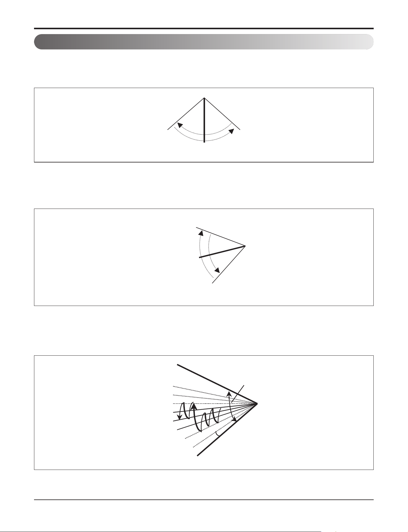
2. Air flow
2.1 Auto swing (left & right)
RightLeft
110° ~ 120°
Open
Close
110° ~ 120°
Mode2
Mode3
Mode4
Mode5
Mode6
Mode7
Mode8
Mode9
OPEN
CLOSED
7~8°
110~120°
• By the horizontal airflow direction control key input, the left/right louver automatically operates with the auto swing or it
is fixed to the desired direction.
2.2 Auto swing (up & down)
• By the auto swing key input, the upper/lower vane automatically operates with the auto swing or it is fixed to the de-
sired direction.
2.3 Chaos swing (up/down)
• By the Chaos swing key input, the upper/lower vane automatically operates with the chaos swing or it is fixed to the
desired direction.
NOTE: Some Models are different by swing width and swing pattern.
Part 2 Functions & Controls
- 18 -
Copyright ©2017 LG Electronics. Inc. All right reserved.
Only for training and service purposes
LGE Internal Use Only
2.4 Air flow step
• Indoor fan motor control have 6 steps.
• Air volume is controlled "SH", "H", "Med", Low" by remote controller.
• "LL" step is selected automatically in Hot start operation.
2.5 Chaos wind (auto wind)
• When "Auto" step selected and then operated, the high, medium, or low speed of the airflow mode is operated for
2~15 sec. randomly by the Chaos Simulation
2.6 Jet Cool Mode Operation
• While in heating mode or Fuzzy operation, the Jet Cool key cannot be input.
When it is input while in the other mode operation (cooling, dehumidification, ventilation), the Jet Cool mode is oper-
ated.
• In the Jet Cool mode, the indoor fan is operated at super-high speed for 30 min. at cooling mode operation.
• In the Jet Cool mode operation, the room temperature is controlled to the setting temperature, 18°C.
• When the sleep timer mode is input while in the Jet Cool mode operation, the Jet Cool mode has the priority.
• When the Jet Cool key is input, the upper/lower vanes are reset to those of the initial cooling mode and then operated
in order that the air outflow could reach further.
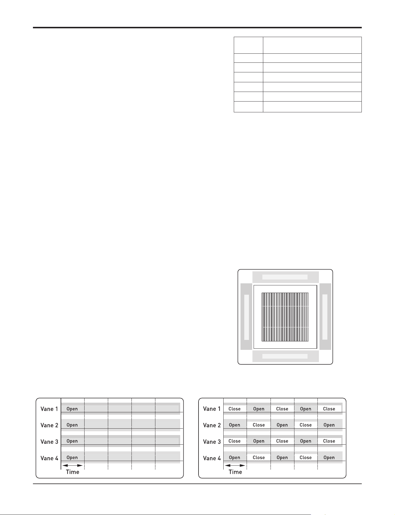
2.7 Swirl wind Swing
• It is the function for comfort cooling/heating operation.
• The diagonal two louvers are opened the more larger
than the other louvers. After one minute, it is opposite.
• Comparison of Air Flow Types
4-Open (conventional) Swirl Swing (New)
LL Very low, In heating mode
L Low
M Med
H High
SH Super high
Auto Chaos wind
Step Discription
Vane 4
Vane 2
Vane 1 Vane 3
Part 2 Functions & Controls
- 19 -
Copyright ©2017 LG Electronics. Inc. All right reserved.
Only for training and service purposes
LGE Internal Use Only
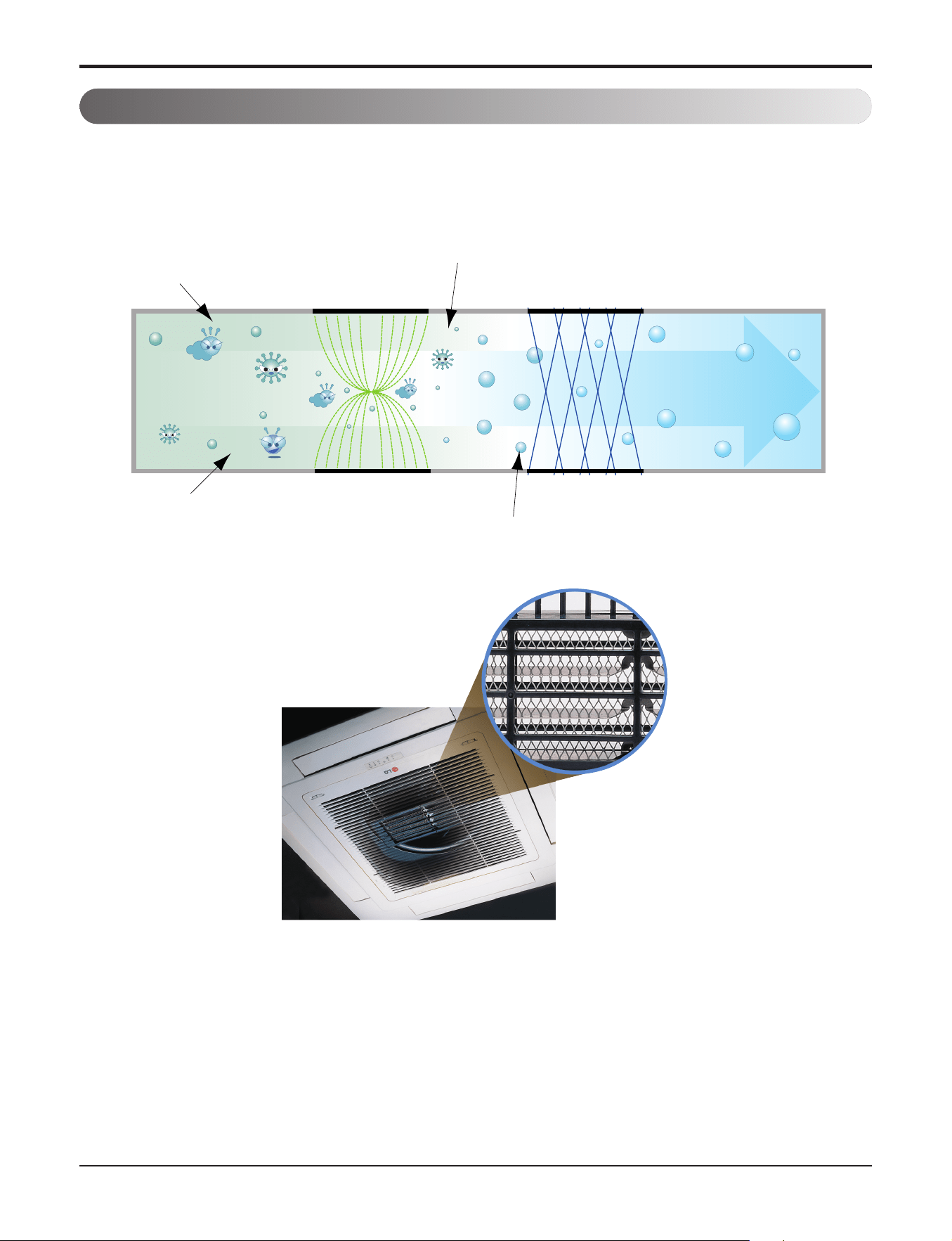
3.1 PLASMA Air Purifying System
The PLASMA Air Purifying System not only removes microscopic contaminants and dust, but also removes house mites,
pollen, and pet fur to help prevent allergic diseases like asthma. This filter that can be used over and over again by sim-
ply washing with water.
3. Air purifying
Ionizer
Photo-Catalyst Coated Mesh
Dust particles
Odour
Dust electrode discharge
Odour molecule
Generating plasma
+
+
+
+
Polluted Air
Purified fresh Air
+4.8KV discharge
+
Part 2 Functions & Controls
- 20 -
Copyright ©2017 LG Electronics. Inc. All right reserved.
Only for training and service purposes
LGE Internal Use Only
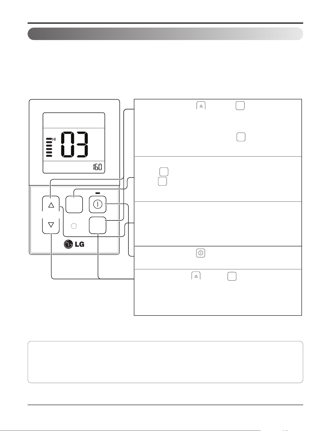
4.1 E.S.P. (External Static Pressure) Setting
4. Installation Functions
This is the function that decides the strength of the wind for each wind level and because this function is to make
the installation easier.
• If you set ESP incorrectly, the air conditioner may malfunction.
• This setting must be carried out by a certificated-technician.
TEMP
FAN
SPEED
OPER
MODE
When pressing the button and button
simultaneously for more than 3 seconds, the system will be
entered into the installer setting mode.
- After entering into the installer setting mode, select the
E.S.P code value by pressing the button.
* E.S.P code value : 03
1
Select the desired air flow rate with
the button. Whenever pressing
the button, [SLo
→
Lo
→
Med
→
Hi
→
Po] will be indicated.
2
Select the desired air flow rate value with the temperature
up(▲), down(▼) button.
* E.S.P value range : 0~255
-
E.S.P value will be indicated at the upper right section of the
display window.
3
When pressing the button, currently established E.S.P
value will be set up.
4
When pressing the button and button simultaneously for
more than 3 seconds after the setting has been completed, the
setting mode will be released.
- If there isn’t any button input for more than 25 seconds, the
installer setting mode will also be released.
5
OPER
MODE
OPER
MODE
FAN
SPEED
FAN
SPEED
OPER
MODE
• Precaution shall be taken not to alter the E.S.P value corresponded to each air flow section.
• E.S.P value can be varied according to the products.
• In the case of going to the next air flow rate stage by pressing the fan-speed button during the setup of the E.S.P value,
the E.S.P value of previous air flow rate will be maintained by remembering the E.S.P value prior to the shift.
Part 2 Functions & Controls
- 21 -
Copyright ©2017 LG Electronics. Inc. All right reserved.
Only for training and service purposes
LGE Internal Use Only
5.1 Hot start
• When heating is started, the indoor fan is stopped or very slow to prevent the cold air carry out
• When the temp. of heat exchanger reach 30°C(model by model), indoor fan is started.
5.2 Self-diagnosis Function
• The air conditioner installed can self-diagnosed its error status and then transmits the result to the central control.
Therefore, a rapid countermeasure against failure of the air conditioner allows easy management and increases the
usage life of air conditioner.
• Refer to trouble shooting guide.
5.3 Soft dry operation
• When the dehumidification operation input by the remote control is received, the intake air temperature is detected and
the setting temp is automatically set according to the intake air temperature.
• While compressor off, the indoor fan repeats low airflow speed and stop.
• While the intake air temp is between compressor on temp. and compressor off temp., 10-min dehumidification opera-
tion and 4-min compressor off repeat.
Compressor ON Temp. ‘ Setting Temp+0.5°C
Compressor OFF Temp. ‘ Setting Temp-0.5°C
• In 10-min dehumidification operation, the indoor fan operates with the low airflow speed.
5. Reliability
Intake air Temp. Setting Temp.
26°C ≤ intake air temp. 25°C
24°C ≤ intake air temp.< 26°C intake air temp. -1°C
22°C ≤ intake air temp. < 24°C intake air temp. -0.5°C
18°C ≤ intake air temp. < 22°C intake air temp.
intake air temp. < 18°C 18°C

Part 2 Functions & Controls
- 22 -
Copyright ©2017 LG Electronics. Inc. All right reserved.
Only for training and service purposes
LGE Internal Use Only
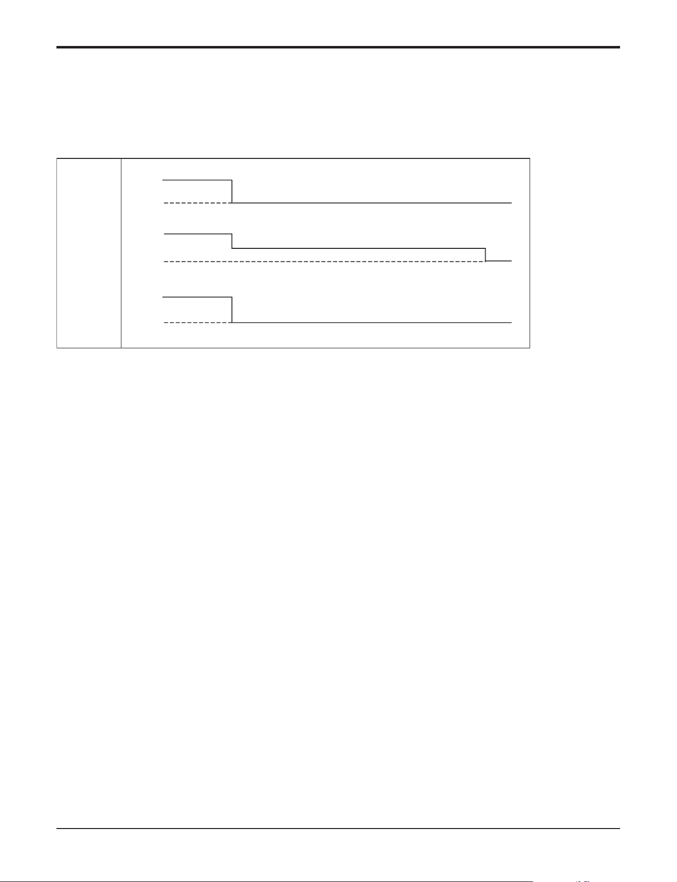
6.1 Cooling & heating Operations
6.1.1 Cooling Mode
• Operating frequency of compressor depends on the load condition, like the difference between the room temp. and
the set temp., frequency restrictions.
• If the compressor operates at some frequency, the operating frequency of compressor cannot be changed within 30
seconds. ( not emergency conditions)
• Compressor turned off when
- intake air temperature is in between ±0.5°C of the setting temp. limit for three minutes continuously.
- intake air temperature reaches below 1.0°C of the temperature of setting temp..
• Compressors three minutes time delay.
- After compressor off, the compressor can restart minimum 3 minutes later.
6. Convenience Functions & Controls
6.1.2 Heating Mode
• Operating frequency of compressor depend on the load condition, The difference between the room temp. and set
temp., frequency restrictions.
• If compressor operates at some frequency, the operating frequency of compressor cannot be changed within 30 sec-
onds.
• Condition of compressor turned off
- When intake air temperature reaches +4°C above the setting temperature.
• Condition of compressor turned on
- When intake air temperature reaches +2°C above the setting temperature.
* Condition of indoor fan turned off
- While in compressor on : indoor pipe temp. < 20°C
- While in compressor off : indoor pipe temp. < 30°C
• While in defrost control, between the indoor and outdoor fans are turned off.
• Compressor 2minutes delay
- After compressor off, the compressor can restart minimum 2 minutes later.
CST/Duct type indoor unit matched with
Universal Outdoor unit
CST/ Duct/CVT type indoor unit
matched with Single Outdoor unit/Multi
Outdoor unit/Multi V Outdoor unit
Thermo ON : +2 °C above setting temp.
Thermo OFF : +4 °C above setting temp.
Thermo ON : Setting temp.
Thermo OFF : +3 °C above setting temp.
NOTE: Some Models are different by temperature of thermo ON/OFF.
Part 2 Functions & Controls
- 23 -
Copyright ©2017 LG Electronics. Inc. All right reserved.
Only for training and service purposes
LGE Internal Use Only
6.3 Auto Operation (Artificial Intelligence)
• When any of operation mode is not selected like the moment of the power on or when 3 hrs has passed since the op-
eration off, the operation mode is selected.
• When determining the operation mode, the compressor, the outdoor fan, and the 4 way valve are off and only the in-
door fan is operated for 15 seconds. Then an operation mode is selected according to the intake air temp at that mo-
ment as follows.
24°C ≤ Inatake Air Temp ‘ Fuzzy Operation for Cooling
21°C ≤ Inatake Air Temp < 24°C ‘ Fuzzy Operation for Dehumidification
Inatake Air Temp < 21°C ‘ Fuzzy Operation for Heating
• If any of the operation modes among cooling / dehumidification / heating mode operations is carried out for 10 sec or
longer before Fuzzy operation, the mode before Fuzzy operation is operated.
6.3.1 Fuzzy Operation for Cooling
• According to the setting temperature selected by Fuzzy rule, when the intake air temp is 0.5°C or more below the set-
ting temp, the compressor is turned off. When 0.5°C or more above the setting temp, the compressor is turned on.
Compressor ON Temp ‘ Setting Temp + 0.5°C
Compressor OFF Temp ‘ Setting Temp + 0.5°C
• At the beginning of Fuzzy mode operation, the setting temperature is automatically selected according to the intake air
temp at that time.
26°C≤ Intake Air Temp ‘ 25°C
24°C≤ Intake Air Temp<26°C ‘ Intake Air Temp + 1°C
22°C≤ Intake Air Temp<24°C ‘ Intake Air Temp + 0.5°C
18°C≤ Intake Air Temp<22°C ‘ Intake Air Temp
Intake Air Temp<18°C ‘ 18°C
• When the Fuzzy key (Temperature Control key) is input after the initial setting temperature is selected, the Fuzzy key
value and the intake air temperature at that time are compared to select the setting temperature automatically accord-
ing to the Fuzzy rule.
• While in Fuzzy operation, the airflow speed of the indoor fan is automatically selected according to the temperature.
6.2 Auto cleaning operation
• Function used to perform Self Cleaning to prevent the Unit from Fungus and bad odor.
• Used after the Cooling Operation before turning the unit off, clean the Evaporator and keep it dry for the next opera-
tion.
• The function is easy to operate as it is accessed through the Remote controller.
Unit
Operation
ON
OFF
Comp.
Indoor
Fan
ON
OFF
ON
OFF
Setting step
OFFL Low
Setting step
(Cooling Only)

Part 2 Functions & Controls
- 24 -
Copyright ©2017 LG Electronics. Inc. All right reserved.
Only for training and service purposes
LGE Internal Use Only
6.3.2 Fuzzy Operation for Dehumidification
• According to the setting temperature selected by Fuzzy rule, when the intake air temp is 0.5°C or more below the set-
ting temp, the compressor is turned off. When 0.5°C or more above the setting temp, the compressor is turned on.
Compressor ON Temp ‘ Setting Temp + 0.5°C
Compressor OFF Temp ‘ Setting Temp+0.5°C
• At the beginning of Fuzzy mode operation, the setting temperature is automatically selected according to the intake air
temp at that time.
26°C ≤ Intake Air Temp ‘ 25°C
24°C ≤ Intake Air Temp<26°C ‘ Intake Air Temp+1°C
22°C ≤ Intake Air Temp<24°C ‘ Intake Air Temp+0.5°C
18°C ≤ Intake Air Temp<22°C ‘ Intake Air Temp
Intake Air Temp<18°C ‘ 18°C
• When the Fuzzy key (Temperature Control key) is input after the initial setting temperature is selected, the Fuzzy key
value and the intake air temperature at that time are compared to select the setting temperature automatically accord-
ing to the Fuzzy rule.
• While in Fuzzy operation, the airflow speed of the indoor fan repeats the low airflow speed or pause as in dehumidifi-
cation operation.
6.3.3 Fuzzy Operation for Heating
• According to the setting temperature selected by Fuzzy rule, when the intake air temp is 3°C or more above the setting
temp, the compressor is turned off. When below the setting temp, the compressor is turned on.
Compressor ON Temp ‘ Setting Temp
Compressor OFF Temp ‘ Setting Temp + 3°C
• At the beginning of Fuzzy mode operation, the setting temperature is automatically selected according to the intake air
temp at that time.
20°C≤Intake Air Temp ‘ Intake Air Temp + 0.5°C
Intake Air Temp<20°C ‘ 20°C
• When the Fuzzy key (Temperature Control key) is input after the initial setting temperature is selected, the Fuzzy key
value and the intake air temperature at that time are compared to select the setting temperature automatically accord-
ing to the Fuzzy rule.
• While in Fuzzy operation, the airflow speed of the indoor fan is set to the high or the medium according to the intake air
temperature and the setting temperature.
Notes: The Temp. of Comp. Turn ON and OFF is different in heating mode and fuzzy operation for heating. Please,
refer 6.1
6.4 Auto restart Operation
• Whenever there is electricity failure to the unit, and after resumption of the power, unit will start in the same mode prior
to the power failure. Memorized condition are on / off condition, operating mode (cooling/ heating), set temperature and
fan speed. The unit will memorize the above conditions and start with same memorized condition.
Part 2 Functions & Controls
- 25 -
Copyright ©2017 LG Electronics. Inc. All right reserved.
Only for training and service purposes
LGE Internal Use Only
6.5 Child Lock Function
6.6 Forced operation
• To operate the appliance by force in case when the remote control is lost, the forced operation selection switch is on
the main unit of the appliance, and operate the appliance in the standard conditions.
• The operating condition is set according to the outdoor temp. and intake air temperature as follows.
• The unit select the last operation mode in 3 hours.
• Operating procedures when the remote control can't be used is as follows :
- The operation will be started if the ON/OFF button is pressed.
- If you want to stop operation, re-press the button.
Indoor temp.
over 24°C
21~24°C
below 21°C
Setting temp.
22°C
23°C
24°C
Setting speed of
indoor fan
High speed
Operating Mode
Cooling
Healthy Dehumidification
Heating
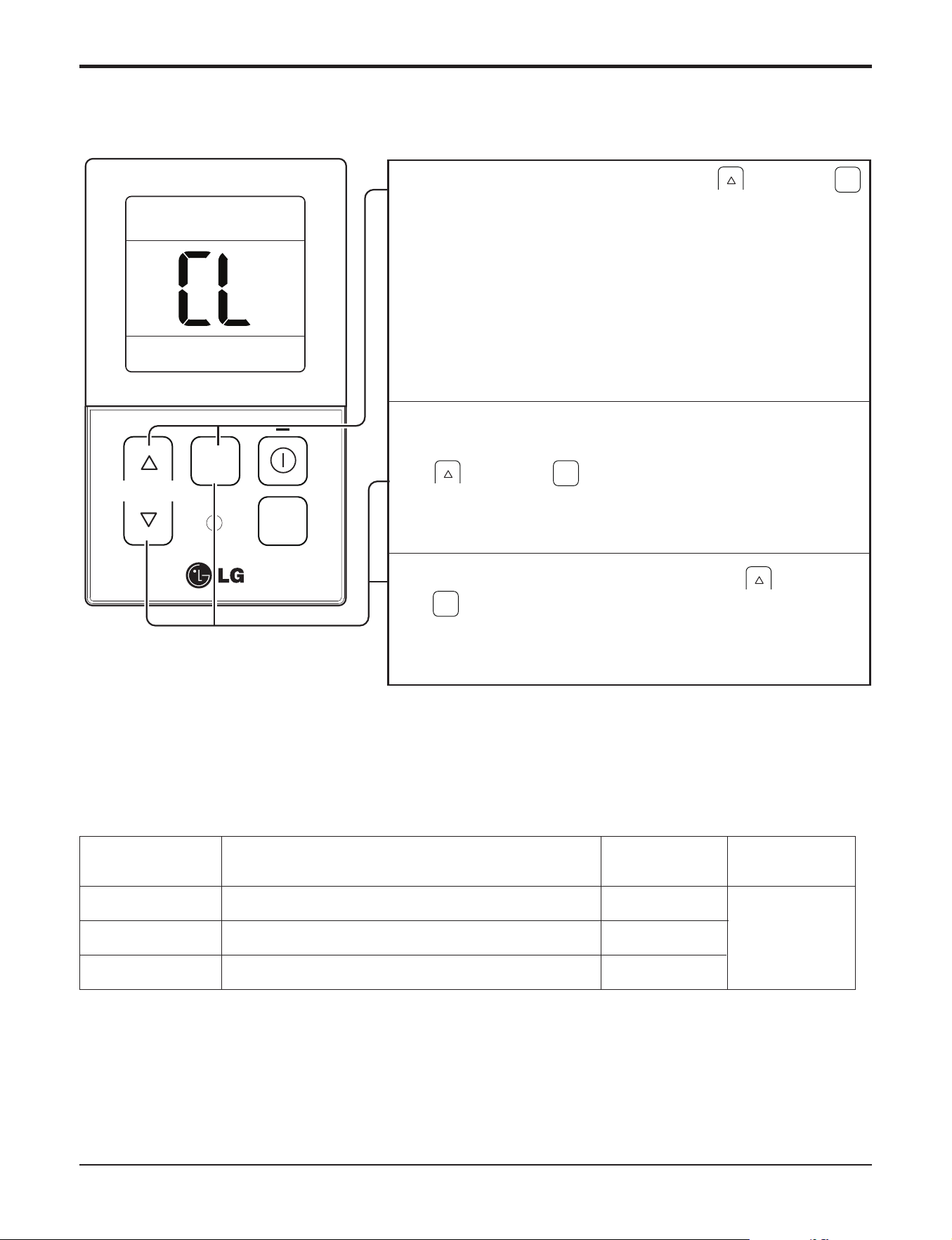
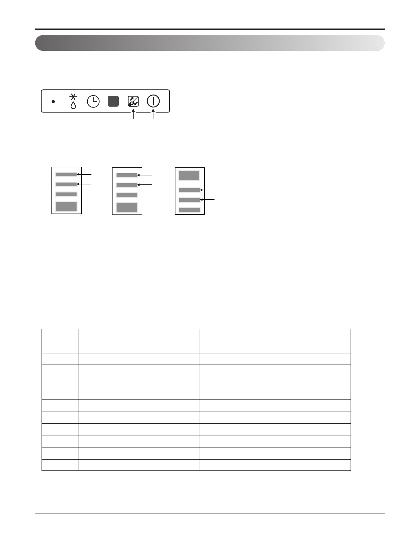
It is the function to use preventing children or others from careless using.
FAN
SPEED
FAN
SPEED
FAN
SPEED
During the operation, when pressing the button and
button for approx. 3 seconds, the ‘Child Lock’ Function can
be used.
- At the time of initial setting of the ‘Child Lock’, the ‘CL’ Will
be indicated approx. 3 seconds at the temperature Display
section before resuming to the previous mode.
After the setting of the ‘CL’, if another button is setup, the
button can not be recognized as the ‘CL’ is indicated at the
temperature display section for approx. 3 seconds.
1
If the ‘CL’ function is wanted to be used under the operation
standby state, press the
button and Button for approx.
3 seconds under the standby mode state and the system will
be the ‘CL’ state.
2
As for the releasing method, when pressing the Button and
button for approx. 3 seconds, the ‘CL’ function can be
released.
3
TEMP
FAN
SPEED
OPER
MODE
Part 2 Functions & Controls
- 26 -
Copyright ©2017 LG Electronics. Inc. All right reserved.
Only for training and service purposes
LGE Internal Use Only
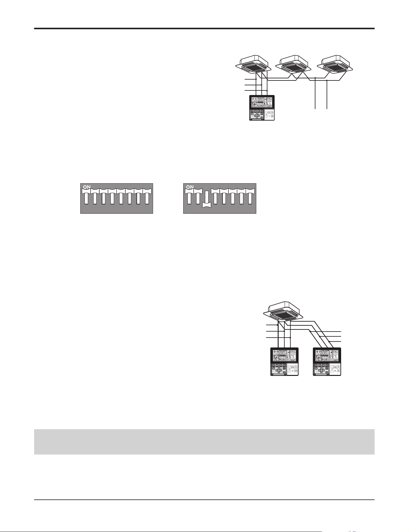
6.7 Group Control
GND
GND
12V
Signal wire
Signal wire
GND
12V
B Y R B Y R
MASTER SLAVE
Signal wire
GND
12V
Signal wire
1. When installing more than 2 units of air conditioner to
one wired remote controller, please connect as the
right figure.
• If it is not event communication indoor unit, set the unit
as slave.
• Check for event communication through the product
manual.
2. When installing more than 2 wired remote controllers to one
air conditioner, please connect as the right picture.
• When installing more than 2 units of wired remote controller to one
air conditioner, set one wired remote controller as master and the
others all as slaves, as shown in the right picture.
• You cannot control the group as shown in the right for some prod-
ucts.
•
Refer to the product manual for more detail.
When controlling multiple indoor units with event communication function with one remote controller, you must change the
master/slave setting from the indoor unit.
- Indoor units, the master/slave configuration of the product after completion of indoor unit power ‘OFF’ and then ‘ON’ the
power after 1 minutes elapsed sign up.
- For ceiling type cassette and duct product group, change the switch setting of the indoor PCB.
- For wall-mount type and stand type product, change the master/slave setting with the wireless remote controller. (Refer to
wireless remote controller manual for detail)
h When installing 2 remote controllers to one indoor unit with event communication function, set the master/slave of the re-
mote controller. (Refer to remote controller master/slave selection)
When controlling the group, some functions excluding basic operation setting, fan level Min/Mid/Max, remote controller
lock setting and time setting may be limited.
<When simultaneously connecting
2 sets of wired remote controller>
• When controlling in groups, set the master/slaver of the remote controller. Refer to Installer setting section on how to set mas-
ter/slave for more detail.
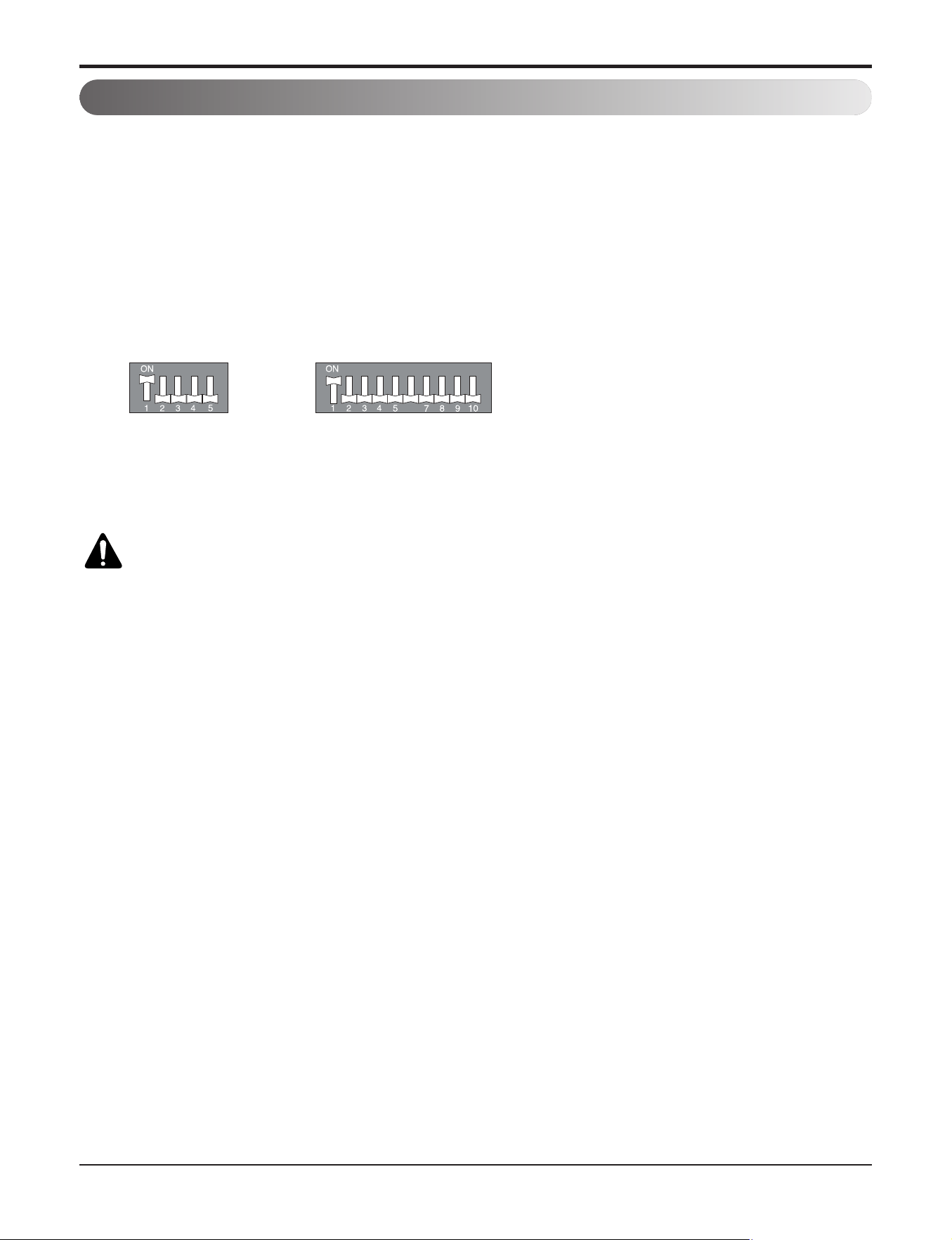
12345678 12345678
#3 switch OFF: Master
(Factory default setting)
#3 switch ON: Slave
Part 2 Functions & Controls
- 27 -
Copyright ©2017 LG Electronics. Inc. All right reserved.
Only for training and service purposes
LGE Internal Use Only
6.8 Sleep Timer Operation
• When the sleep time is reached after <1,2,3,4,5,6,7,0(cancel) hr> is input by the remote control while in appliance op-
eration, the operation of the appliance stops.
• While the appliance is on pause, the sleep timer mode cannot be input.
• While in cooling mode operation, 30 min later since the start of the sleep timer, the setting temperature increases by
1°C. After another 30 min elapse, it increases by 1°C again.
• When the sleep timer mode is input while in cooling cycle mode, the airflow speed of the indoor fan is set to the low.
• When the sleep timer mode is input while in heating cycle mode, the airflow speed of the indoor fan is set to the
medium.
6.9 Timer(On/Off)
6.9.1 On-Timer Operation
• When the set time is reached after the time is input by the remote control, the appliance starts to operate.
• The timer LED is on when the on-timer is input. It is off when the time set by the timer is reached.
• If the appliance is operating at the time set by the timer, the operation continues.
While in Fuzzy operation, the airflow speed of the indoor fan is automatically selected according to the temperature.
6.9.2 Off-Timer Operation
• When the set time is reached after the time is input by the remote control, the appliance stops operating.
• The timer LED is on when the off-timer is input. It is off when the time set by the timer is reached.
• If the appliance is on pause at the time set by the timer, the pause continues.
6.10 Weekly Program
• If necessary, an operator can make an On/Off reservation of the product for a period of one week.
- On/Off schedule of operation for a period of ONE week.
• No need to turn the unit On/OFF manually during working days.
On/Off time is scheduled in micom of the wired remote control.
Operation Time Table (Example)
Mon Tue Wed Thu Fri Sat Sun
OFF
Setting
Temp.
On
Off
25°C 25°C 25°C 25°C 25°C
09:00
12:00
08:00
17:00
09:00
12:00
08:00
12:00
09:00
12:00
Part 2 Functions & Controls
- 28 -
Copyright ©2017 LG Electronics. Inc. All right reserved.
Only for training and service purposes
LGE Internal Use Only
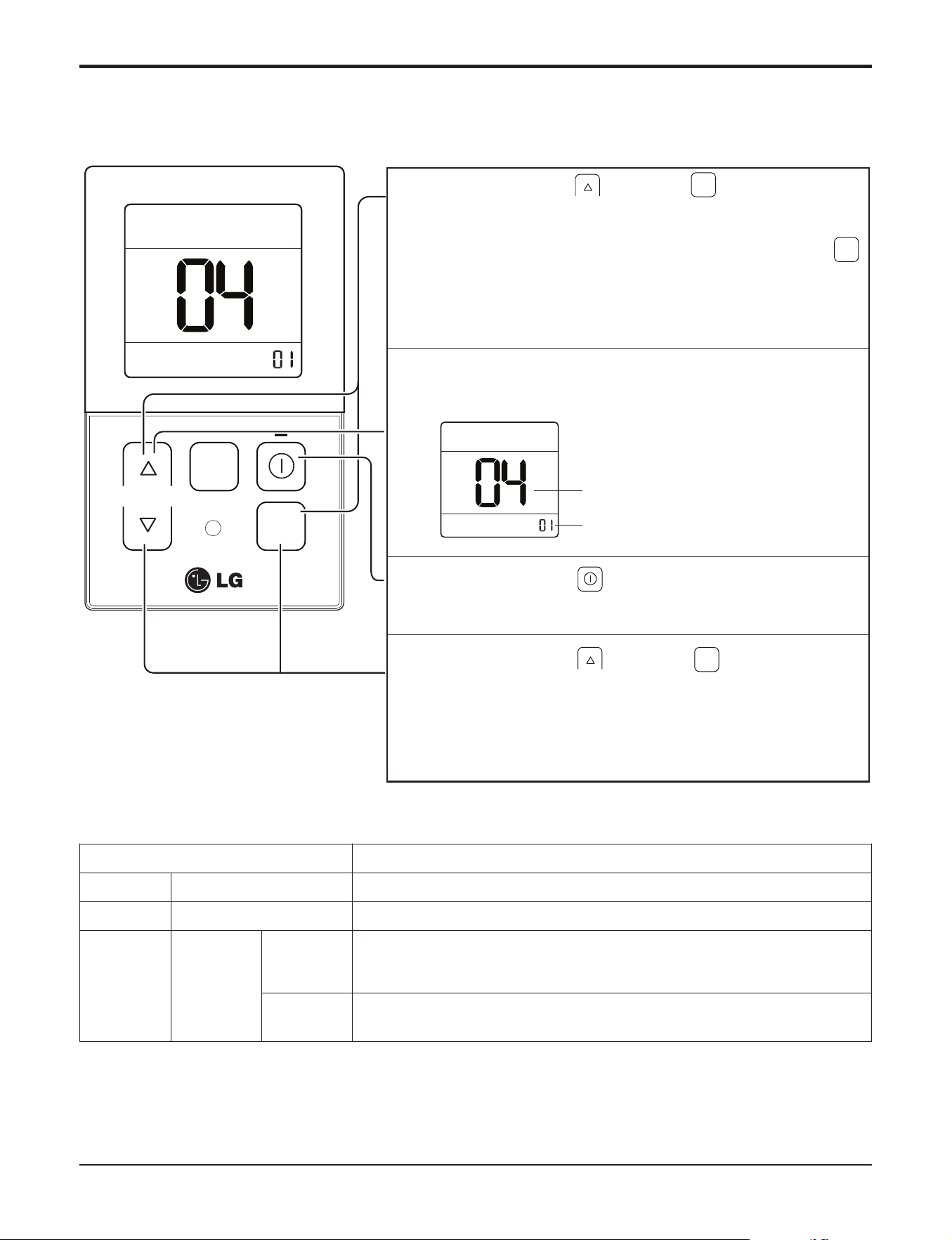
6.11 Two Thermistor Control
When pressing the button and button
simultaneously for more than 3 seconds, the system will be
entered into the installer setting mode.
- After entering into the installer setting mode, select the
thermistor sensor setting code value by pressing the
button.
* Thermistor sensor selection code value : 04
1
Select the desired setting value with the temperature up(▲),
down(▼) button.
2
When pressing the button, currently established
thermistor sensor location will be set up.
3
When pressing the button and button
simultaneously for more than 3 seconds after the setting
has been completed, the setting mode will be released.
- If there isn’t any button input for more than 25 seconds,
the installer setting mode will also be released.
4
OPER
MODE
OPER
MODE
Code value
*Setting value
01: Remote
controller
02: Indoor unit
03: 2TH
OPER
MODE
Value
TEMP
FAN
SPEED
OPER
MODE
h The function of 2TH has different operation characteristics according to the product.
<Thermistor Table>
This is the function to select the temperature sensor to judge the room temperature.
Temperature sensor selection Function
01 Remote controller Operation in remote controller temperature sensor
02 Indoor unit Operation in indoor unit temperature sensor
03 2TH
Cooling
Operation of higher temperature by comparing indoor unit's and wired remote
controller’s temperature.
(There are products that operate at a lower temperature.)
Heating
Operation of lower temperature by comparing indoor unit's and wired remote
controller's temperature.
Part 2 Functions & Controls
- 29 -
Copyright ©2017 LG Electronics. Inc. All right reserved.
Only for training and service purposes
LGE Internal Use Only
7.2 Space control
Vanes angle can be controlled by pair, considering its
installation environment.
• For example direct drafts can be annoying, leading to
discomfort and reduced productivity vane control
helps to eliminate this problem.
• Easily controlled by wired remote control.
• Air Flow can be controlled easily regarding any space
environment.
7.3 Auto Elevation Grille
• Auto Elevation Grille is automatically down to height
of max. 3.1 m. So it enables to install the Indoor unit
at high ceiling space. And Auto Elevation Grille
makes you cleaning the filter easily.
7.1 Low Ambient control
• This Function is for cooling operating in outdoor low temperature .
• If outdoor temperature drops below certain temperature, liquid back is prevented by reducing outdoor fan speed.
• It can prevent frosting of evaporator and keep cooling operation
7. Special Function & KIT
T2°C
T1°C
Outdoor pipe
Outdoor
Fan Speed
Setting Speed Off Off
Setting
Speed
Setting
Speed
Part 2 Functions & Controls
- 30 -
Copyright ©2017 LG Electronics. Inc. All right reserved.
Only for training and service purposes
LGE Internal Use Only
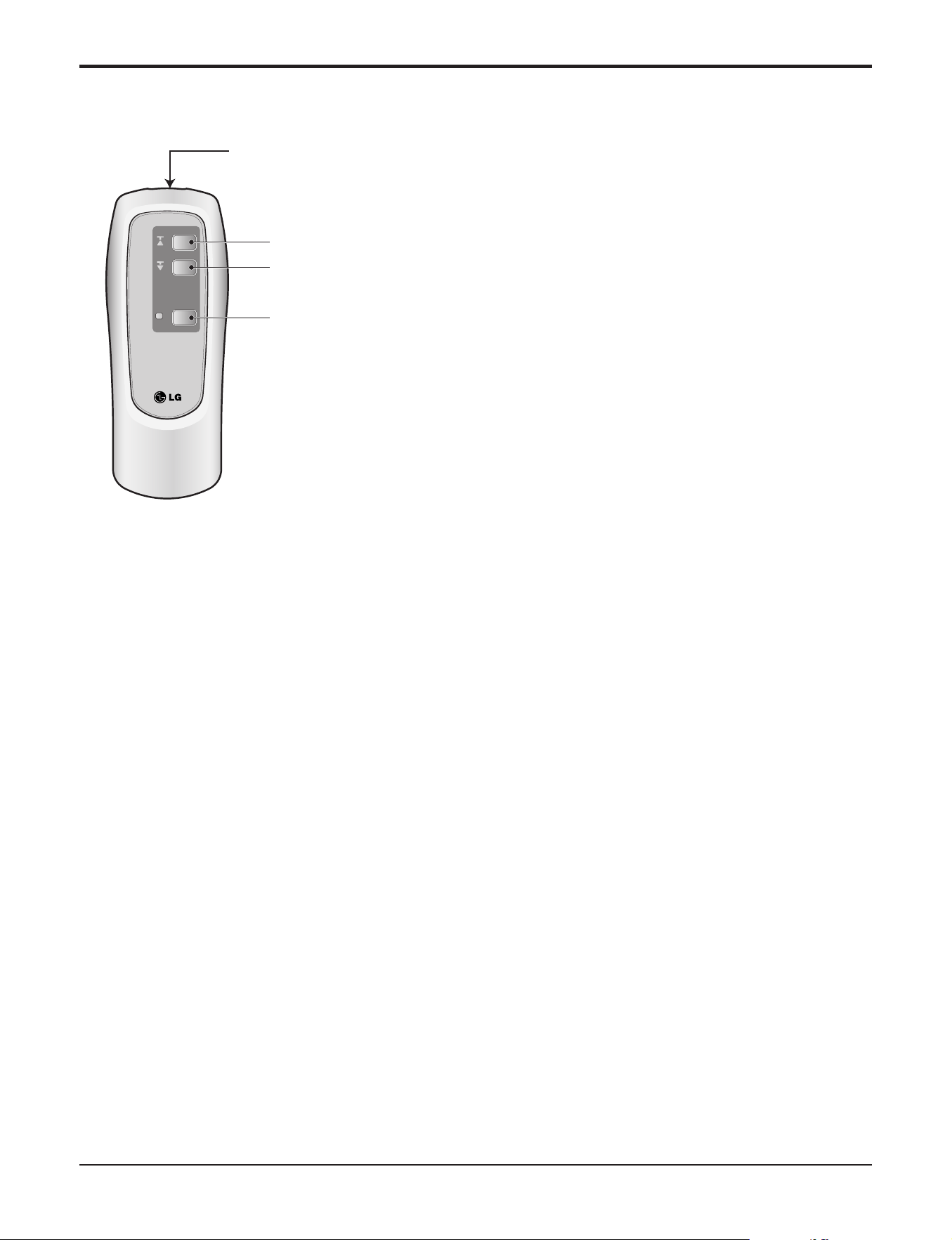
n ELEVATION GRILL (REMOTE CONTROLLER_Accessory)
• How to Use Remote Controller
• Main Components of Lift Grill
As for operation of Remote Controller, use it by directing the trans-
mitter part of Remote Controller to the receiver part of front panel
directly under front panel.
• Do not drop it down or into water. Or else there is worry about trou-
ble failure.
• Do not press hard the Remote Controller button with nail (ballpoint
pen or other sharp substance). Or else there is worry about trouble
failure.
• In case when obstacle such as curtain hides the signal reception
part of receiver in between the space interval, Remote Controller
operation is infeasible.
¿ Lift grill front panel assembly
¡ Bolts for installation (4 EA, P/No. 3A00255K)
¬ Instruction manual
√ Remote Controller for lift grill
Ascend
Signal transmitter
Descend
Stop
Part 2 Functions & Controls
- 31 -
Copyright ©2017 LG Electronics. Inc. All right reserved.
Only for training and service purposes
LGE Internal Use Only
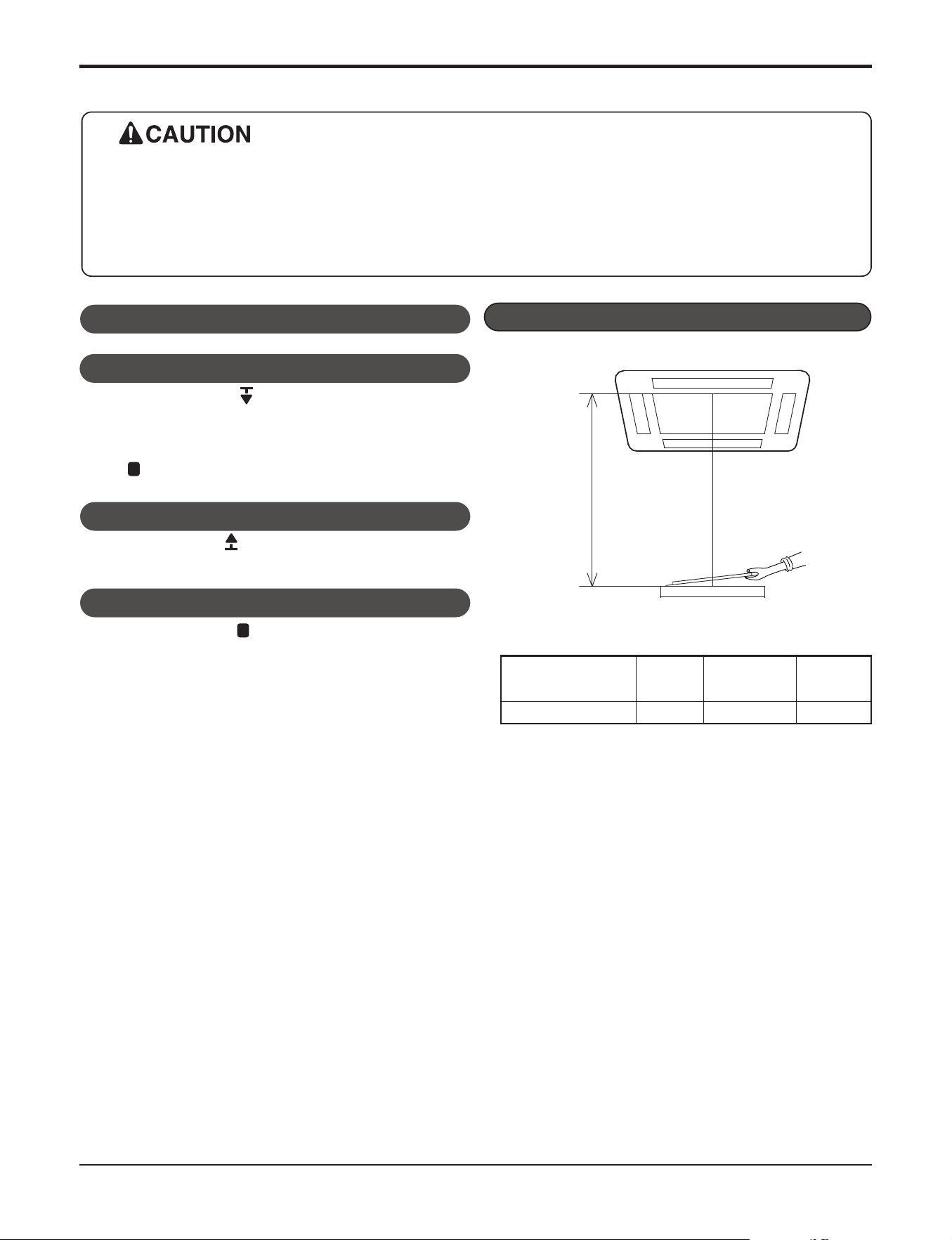
7.4 Defrost Control (Heating)
• Defrost operation is controlled by timer and sensing temperature of outdoor pipe.
• The first defrost starts only when the outdoor pipe temperature falls below -11°C after starting of heating operation and
more than 10 minutes operation of compressor.
• Defrost ends after 15 minutes passed from starting of defrost operation when the outdoor rises over 40°C even before
12 minutes.
• The second defrost starts only when the outdoor pipe temperature falls below – 6°C after from ending of the first de-
frost and more than 10 minutes operation of compressor.
Automatic stop distance
S
If you want to change automatic distance setting,
consult with your sale agency.
Automatic Stop Distance of Grill
Ceiling height
Low
Medium
High
(
Height: 3~4 m)
Automatic stop distance
1.5±0.5 m 2.5±0.5 m 3.5±0.5 m
- Depress the down button( ).
Then suction grill descends and stops automatically at a certain
distance.
- You may stop it at wanted distance point by depressing the stop but-
ton ( ) when descending.
- Depress the up button( ).
Then suction grill goes up and enters into the front panel.
1. Stop the Air Conditioner Operation
2. Descend the Suction Grill
3. Raise the Suction Grill
- Depress the stop button( ).
Make use of this when you want to stop it at your wished posi-
tion.
4. Stop the Suction Grill during Rising
• Always stop the air conditioner operation for safety before operating lift grill.
• Take heed _ there is worry about dust fall etc. when suction grill descends.
• In case when the set automatic stop distance goes wrong, check the set value of operation panel and con-
firm if there is neither obstacle nor mankind.
• When you are not to remove obstacle, stop the operation before touching the obstacle.
• How to Operate the Lift Grill

Part 3. Basic Control
- 32 -
Copyright ©2017 LG Electronics. Inc. All right reserved.
Only for training and service purposes
LGE Internal Use Only
Part 3. Basic Control
1. Normal operation..............................................................................................................33
2 Compressor control .........................................................................................................33
3. EEV( Electronic Expansion Valve) control ....................................................................33
4. Oil return control .............................................................................................................34
5. Defrost control .................................................................................................................34
6. Protection control ............................................................................................................35
6.1 High pressure protection control ..........................................................................35
6.2 Low pressure protection control ..........................................................................35
6.3 Discharge temperature control ...........................................................................35
6.4 Input Current control ...........................................................................................35
Part 3. Basic Control
- 33 -
Copyright ©2017 LG Electronics. Inc. All right reserved.
Only for training and service purposes
LGE Internal Use Only
Basic principle is to control the rpm of the motor by changing the working frequency of the compressor.
Three phase voltage is supplied to the motor and the time for which the voltage will supplied is controlled by IPM
(intelligent power module).
Switching speed of IPM defines the variable frequency input to the motor.
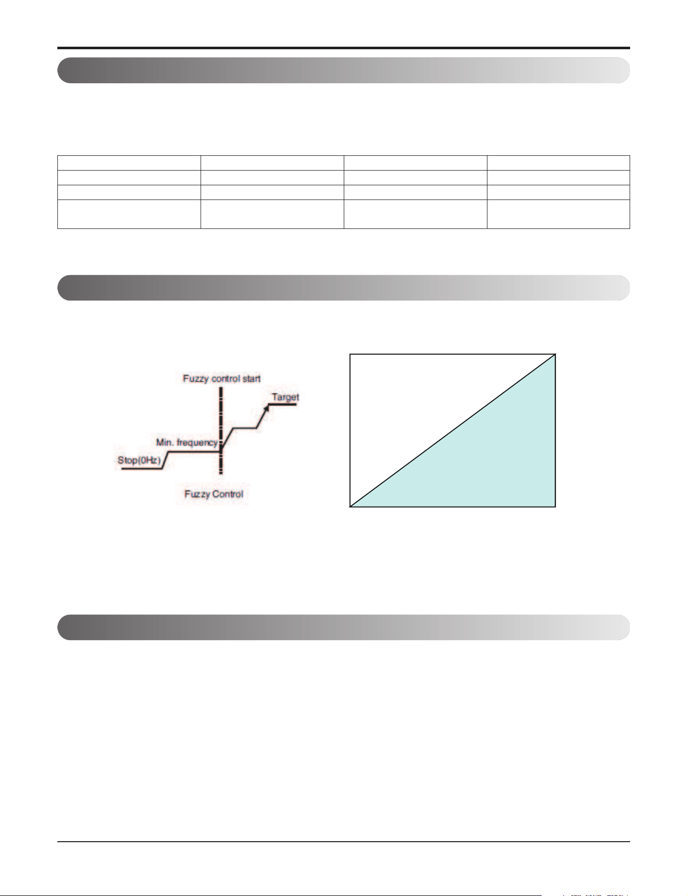
1. Normal operation
Fuzzy control : Maintain evaporating temperature (Te) to be constant on cooling mode and constant condensing temper-
ature (Tc) on heating mode by fuzzy control to ensure the stable system performance.
2. Compressor control
Cooling and heating load
System capacity
Linear control
Inverter linear control as cooling and heating load increasing
Actuator Cooling operation Heating operation Stop state
Compressor Fuzzy control Fuzzy control Stop
Fan Fuzzy control Fuzzy control Stop
EEV
Super heating
fuzzy control
Super heating & Sub cooling
fuzzy control
Min. Pulse
EEV operates with fuzzy control rules to keep the degree of superheat (about 2~3℃) at the evaporator outlet status.
The degree of superheat = Tsuction – Tevaporation
Tsuction : temperature at suction pipe sensor(℃)
Tevaporation : evaporation temperature (℃)
3. EEV( Electronic Expansion Valve) control
Part 3. Basic Control
- 34 -
Copyright ©2017 LG Electronics. Inc. All right reserved.
Only for training and service purposes
LGE Internal Use Only
Outdoor unit
Oil return operation recovers oil amount in compressor by collecting oil accumulated in pipe.
Each cycle component operates as shown on the below table during oil return operation.
4. Oil return control
Defrost operation eliminates ice accumulated on heat exchanger, recovering performance of heat exchanger.
Each cycle component operates as shown on the below table during defrost operation.
5. Defrost control
Component Starting Running Ending
Compressor Normal control Setting value Normal control
Fan Normal control Off Normal control
EEV (Thermo on) Normal control Setting value Normal control
EEV (Thermo off) Min. Pulse Setting value Min. Pulse
4 way valve On Off On
Component Starting Running Ending
Fan Normal control Off Normal control
Defrost signal Off On Off
Outdoor unit
Component Starting Running Ending
Compressor Normal control Setting value Normal control
Fan Normal control Off Normal control
EEV (Thermo on) Normal control Setting value Normal control
EEV (Thermo off) Min. Pulse Setting value Min. Pulse
4 way valve On Off On
Component Starting Running Ending
Fan Normal control Off Normal control
Oil return signal Off On Off
Indoor unit
Indoor unit

Part 3. Basic Control
- 35 -
Copyright ©2017 LG Electronics. Inc. All right reserved.
Only for training and service purposes
LGE Internal Use Only
6.1 High pressure protection control
6.2 Low pressure protection control
n Cooling Mode
n Heating mode
6.4 Input Current control
6. Protection control
h Remarks: The data of pressure and frequency are different model by model.
Pressure range Compressor
Pd ≥ 4069 kPa Off
3938 kPa ≤ Pd < 4069 kPa
3Hz down
3840 kPa ≤ Pd < 3938 kPa
3Hz down
3709 kPa ≤ Pd < 3840 kPa
Frequency holding
3611 kPa ≤ Pd < 3709 kPa
3 Hz up
Pd < 3611 kPa
Normal control
Pressure range Compressor
Pe
>
310 kPa
Normal control
278 kPa
<
Pe ≤ 310 kPa
3Hz down
245 kPa
<
Pe ≤ 278 kPa
3Hz down
212 kPa
<
Pe ≤ 245 kPa
3Hz down
Pe ≤ 212 kPa Off
Pressure range Compressor
Pe
>
294 kPa
Normal control
255 kPa
<
Pe ≤ 294 kPa
3Hz down
229 kPa
<
Pe ≤ 255 kPa
3Hz down
203 kPa
<
Pe ≤ 229 kPa
3Hz down
Pe ≤ 203 kPa Off
6.3 Discharge temperature control
Temperature range Compressor
Td ≥ 105 ℃ Off
100℃ ≤ Td
<
105℃
5Hz down
95℃ ≤ Td
<
100℃
5Hz down
93℃ ≤ Td
<
95℃
Frequency holding
90℃ ≤ Td
<
93℃
3 Hz up
Td
<
90℃
Normal control
Normal control Frequency down Comp off
Input current Less than 10A 14A or less Over than 14A

Part 4. Test Run
- 36 -
Copyright ©2017 LG Electronics. Inc. All right reserved.
Only for training and service purposes
LGE Internal Use Only
Part 4. Test Run
1. Check before Test Run.....................................................................................................37
2. Test Run Flow chart .........................................................................................................38
3. Test Running.....................................................................................................................39

Part 4. Test Run
- 37 -
Copyright ©2017 LG Electronics. Inc. All right reserved.
Only for training and service purposes
LGE Internal Use Only
Check to see whether there is any refrigerant leakage, and check whether the power or transmission
cable is connected properly.
Check liquid pipe and gas pipe valves are fully opened.
NOTE: Be sure to tighten caps.
Confirm that 500 V megger shows 2.0 MΩ or more between power supply terminal block and
ground. Do not operate in the case of 2.0 MΩ or less.
NOTE: Never carry out mega ohm check over terminal control board.
Otherwise the control board may break.
Immediately after mounting the unit or after leaving it turned off for an extended length of
time, the resistance of the insulation between the power supply terminal board and the
ground maydecrease to approx. 2.0 MΩ as a result of refrigerant accumulation in the internal
compressor.
If the insulation resistance is less than 2.0 MΩ, turn on the main power supply.
1
2
3
1. Check before Test Run
Part 4. Test Run
- 38 -
Copyright ©2017 LG Electronics. Inc. All right reserved.
Only for training and service purposes
LGE Internal Use Only
• Each indoor unit should be tested.
• If the unit has accessory, it should be tested.
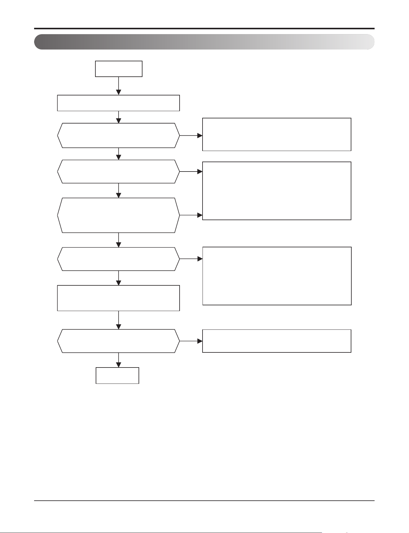
Is cold air discharged for
more than 3 minutes ?
START
Test operation for indoor unit
Operation mode change
to Heating mode
Operate the unit in cooling mode.
Does Test operation start?
*Refer to Part 5.Trouble Shooting
- 4. Gas Charging, 6.Electric Parts
Yes
No
Yes
*Refer to Part 5.Trouble Shooting
- 4. Gas Charging, 5.Cycle Parts
No
Is hot air discharged ?
After Hot Start
Yes
No
Is there any temperature
difference between intake and
discharged air?
Yes
No
Is the operating current
normal ?
Yes
Normal
*Refer to Part 5.Troulbe Shooting
No
* Check the load (In/Out Temp.)
* Check pipe length and amount of
refrigerant
* Check for abnormal sound in
outdoor unit (comp.,Fan, others )
2. Test Run Flow chart
Part 4. Test Run
- 39 -
Copyright ©2017 LG Electronics. Inc. All right reserved.
Only for training and service purposes
LGE Internal Use Only
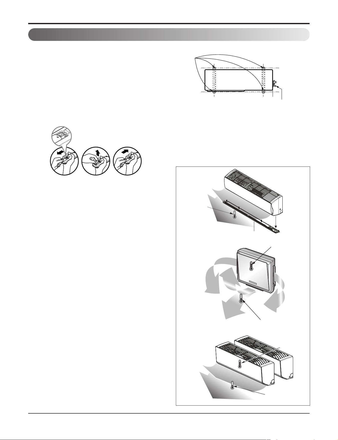
• Check that all tubing and wiring have been properly con-
nected.
• Check that the gas and liquid side service valves are fully
open.
3.1.1 Prepare remote controller
❶ Remove the battery cover by pulling it according to
the arrow direction.
❷ Insert new batteries making sure that the (+) and (–)
of battery are installed correctly.
❸ Reattach the cover by pushing it back into position.
NOTE:
• Use 2 AAA(1.5volt) batteries. Do not use rechargeable
batteries.
• Remove the batteries from the remote controller if the sys-
tem is not going to be used for a long time.
3.1.2 Precautions in test run
n The initial power supply must provide at least 90% of
the rated voltage.
Otherwise, the air conditioner should not be operated.
n For test run, carry out the cooling operation firstly
even during heating season. If heating operation is
carried out firstly, it leads to the trouble of compres-
sor. Then attention must be paid.
n Carry out the test run more than 5 minutes without
fail. (Test run will be cancelled 18 minutes later auto-
matically)
n The forced operation is started by pressing button for
2 seconds.
The test run is started by pressing button for 3~6 sec-
onds.
n To cancel the test run, press any button.
3.1.3 Settlement of outdoor unit
n Anchor the outdoor unit with a bolt and nut(ø10mm)
tightly and horizontally on a concrete or rigid mount.
n When installing on the wall, roof or rooftop, anchor the
mounting base securely with a nail or wire assuming the
influence of wind and earthquake.
n In the case when the vibration of the unit is conveyed to
the hose, secure the unit with an anti-vibration rubber.
3.1.4 Evaluation of the performance
Operate unit for 15~20 minutes, then check the system re-
frigerant charge:
1. Measure the pressure of the gas side service valve.
2.
Measure the temperature of the intake and discharge of air.
3.
Ensure the difference between the intake temperature and the
discharge is more than 8°C (Cooling) or reversely (Heating).
Bolt
Tubing connection
Discharge
temperature
Discharge air
Discharge
temperature
Discharge air
Intake temperature
Chassis cover
Discharge
temperature
Discharge air
Intake
temperature
3.1 SPLIT, ART cool, ART cool deluxe Type
3. Test Running

Part 4. Test Run
- 40 -
Copyright ©2017 LG Electronics. Inc. All right reserved.
Only for training and service purposes
LGE Internal Use Only
3.2 Ceiling Cassette Type
3.2.1 PRECAUTIONS IN TEST RUN
• The initial power supply must provide at least 90% of the rated voltage.
Otherwise, the air conditioner should not be operated.
CAUTION:
① For test run, carry out the cooling operation first even during winter season. If heating operation is carried out
first, it leads to the trouble of compressor.
② Carry out the test run more than 5 minutes without stopping.
(Test run will be cancelled 18 minutes later automatically)
• The test run is started by pressing the room temperature checking button and down timer button for 3 seconds
at the same time.
• To cancel the test run, press any button.
3.2.2 CHECK THE FOLLOWING ITEMS WHEN INSTALLATION IS COMPLETE
• After completing work, be sure to measure and record trial run properties, and store measured data, etc.
• Measuring data are room temperature, outside temperature, suction temperature, blow out temperature,
air velocity, air volume, voltage, current, presence of abnormal vibration and noise, operating pressure, piping
temperature.
• As to the structure and appearance, check following items.
o Is the circulation of air adequate?
o Is the drainage OK?
o Is the heat insulation complete
(refrigerant and drain piping)?
o Is there any leakage of refrigerant?
o Does the romote controller works properly?
o Is there any error on wiring?
o Aren't terminal screws loosened?
M4......118N.cm{12kgf.cm} M5......196N.cm{20kgf.cm}
M6......245N.cm{25kgf.cm} M8......588N.cm{60kgf.cm}

Part 5. Trouble Shooting
- 41 -
Copyright ©2017 LG Electronics. Inc. All right reserved.
Only for training and service purposes
LGE Internal Use Only
Part 5. Trouble Shooting
1. Self-diagnosis Function.................................................................................................42
1.1 Error Indicator (Indoor)................................................................................................42
1.2 Error Indicator (Outdoor) .............................................................................................43
2. Pump Down.....................................................................................................................44
3. Evacuation ......................................................................................................................45
4. Gas Charging..................................................................................................................46
5. Cycle Part........................................................................................................................47
6. Electronic Parts ..............................................................................................................48
6.1 The Product doesn t operate at all..............................................................................48
6.2 The Product doesn't operate with the remote controller .............................................49
6.3 The Compressor/Outdoor Fan are don't operate ........................................................49
6.4 When indoor Fan does not operate.............................................................................51
6.5 When the louver does not operate..............................................................................52
6.6 Troubleshooting Indoor Error ......................................................................................53
6.7 Troubleshooting Outdoor Error....................................................................................59
Part 5. Trouble Shooting
- 42 -
Copyright ©2017 LG Electronics. Inc. All right reserved.
Only for training and service purposes
LGE Internal Use Only
1. Self-diagnosis Function
1.1 Error Indicator (Indoor)
Ceiling Cassette Type Display
The number of times to blink = Error code
10 degrees 1 degrees
Error Indicator
•
The function is to self-diagnoisis airconditioner and express the troubles identifically if there is any trouble.
•
Error mark is ON/OFF for the operation LED of evaporator body in the same manner as the following table.
•
If more than two troubles occur simultaneously, primarily the highest trouble fo error code is expressed.
• After error occurrence, if error is released, error LED is also released simultaneously.
• To operate again on the occurrence of error code, be sure to turn off the power and then turn on.
• Having or not of error code is different from Model.
Indoor Error
00 No Error ON
01 Indoor Room themistor error OFF
02 Indoor in-piping sensor error OFF
03 Remote controller error OFF
04 Drain Pump error OFF
05 Communcation error between in and out OFF
06 Indoor Out-Piping sensor error OFF
07 Differnt mode operation OFF
09 EEPROM Check Sum Error OFF
10 Indoor BLDC Fan Lock OFF
Error code
Description
Indoor Status
Standard Libero Type Display
The number of times to blink = Error code
Cooling
Heating
Plasma
1 degrees
10 degrees
Libero-R
Cooling
Heating
Preheating
1 degrees
10 degrees
Libero-E
Power
Plasma
Preheating
1 degrees
10 degrees
Artcool Mirror
Part 5. Trouble Shooting
- 43 -
Copyright ©2017 LG Electronics. Inc. All right reserved.
Only for training and service purposes
LGE Internal Use Only
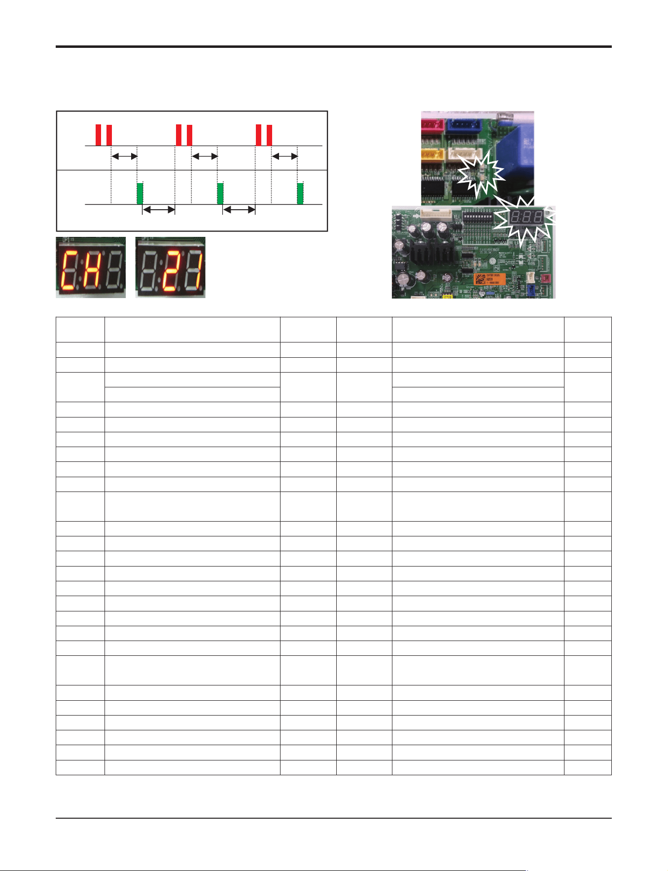
1.2 Error Indicator (Outdoor)
Outdoor Error
Ex) Error 21 (DC Peack)
1 Time 1 Time 1 Time
2 Times2 Times2 Times
1 Sec.
2 Sec. 2 Sec.
1 Sec. 1 Sec.
LED01G
(RED)
LED02G
(GREEN)
◑ :
A light on the display panel is blink.
Error
Code
Contents
LED01G/M
(Red)
LED02G/M
(Green)
case of Error
Outdoor
Status
21 DC Link Peak (IPM Fault)
2times ◑ 1times ◑
Over Rated Current
Off
22 CT 2 (Max CT)
2times ◑ 2times ◑
Input Over Current
Off
23
DC Link Low Volt.
2times ◑ 3times ◑
DC Link Volt is below 140Vdc
Off
DC Link High Volt.
DC Link Volt is above 420Vdc
25 Low Voltage/Over Voltage
2times ◑ 5times ◑
Abnormal AC Volt Input
Off
26 DC Compressor Position Error
2times ◑ 6times ◑
Compressor Starting Fall Error
Off
27 PSC/PFC Fault Error
2times ◑ 7times ◑
Over Inverter PCB input current
Off
29 COMP Over Current
2times ◑ 9times ◑
Over Inverter Compressor Current
Off
32 D-Pipe High
3times ◑ 2times ◑
D-Pipe Temp. High
Off
35 Low Pressure Error
3times ◑ 5times ◑
Excessive decrease of Low Pressure
Off
39 Communication Error
3times ◑ 9times ◑
Communication Error Between PFC
Micom and INV Micom
Off
40 CT Sensor (Open/Short)
4times ◑
○
CT Circuit Malfunction
Off
41 INV. D-Pipe Th Error
4times ◑ 1times ◑
Open/Short
Off
43 High Pressure Sensor Error
4times ◑ 3times ◑
Open/Short
Off
44 Outdoor Air Th Error
4times ◑ 4times ◑
Open/Short
Off
45 Cond. Mid-Pipe Th Error
4times ◑ 5times ◑
Open/Short
Off
46 Suction Pipe Th Error
4times ◑ 6times ◑
Open/Short
Off
48 Cond. Out-Pipe Th Error
4times ◑ 8times ◑
Open/Short
Off
51 Capacity Over
5times ◑ 1times ◑
Over combination
Off
53 Signal Error (Indoor <-> Outdoor)
5times ◑ 3times ◑
Communication Poorly
Off
54 3-Phase Wrong wiring
5times ◑ 4times ◑
3-Phase Wrong Wring of Outdoor Unit
(Reverse Phase/Omission of Phase)
Off
60 EEPROM Check Sum Error
6times ◑
○
Check Sum Mismatching
Off
61 Cond. Pipe Th High
6times ◑ 1times ◑
Cond. Temp. High
Off
62 Heaksink Th High
6times ◑ 2times ◑
Heatsink Temp. High
Off
65 Heaksink Th Error
6times ◑ 5times ◑
Open/Short
Off
67 Outdoor BLDC Fan Lock
6times ◑ 7times ◑
Outdoor Fan is not operation
Off
73 PFC Fault Error(S/W)
7times ◑ 3times ◑
Over Current of Outdoor Unit PFC
Off
Part 5. Trouble Shooting
- 44 -
Copyright ©2017 LG Electronics. Inc. All right reserved.
Only for training and service purposes
LGE Internal Use Only
2. Pump Down
This function gathers the refrigerant present in the system to ODU
Use this function to store refrigerant of system in ODU for leakage or IDU replacement.
• Procedure
n
This function start Dip switch setting status of ODU PCB.
(1) Set the Dip switch as follow after shutting the power source down.
(2) Reset the power.
(3) Check that the Red LED of PCB is on during work.(The indoor unit is operated by force.)
(4) Pump down during forced cooling operation.
CAUTION
1. Use pump down function within guaranteed temperature range
IDU : 20~32C
ODU : 0~40C
2. Make certain that IDU doesn't run with thermo off mode during operation
3. After the compressor is starting operation, please complete Pump Down within 4 minutes.
4. Pump Down can be stopped (The compressor is turned off), because of compressor protection.
In this case, reset the power.
6
18,24,30kBtu/h class 36,42kBtu/h class
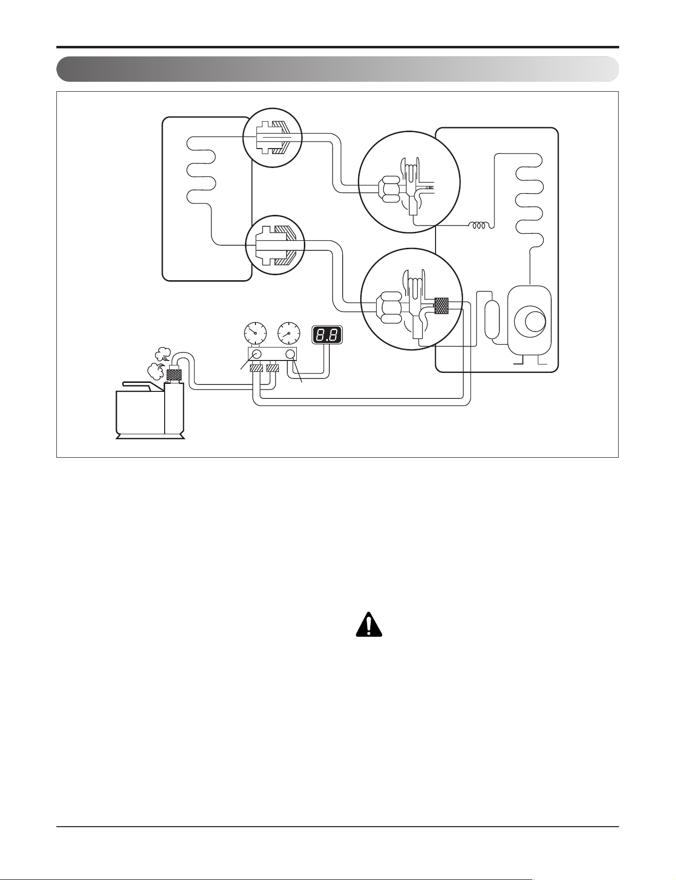
Part 5. Trouble Shooting
- 45 -
Copyright ©2017 LG Electronics. Inc. All right reserved.
Only for training and service purposes
LGE Internal Use Only
• Procedure
(1) Connect the vacuum pump to the center hose
of charge set center hose
(2) Evacuation for approximately one hour.
– Confirm that the gauge needle has moved to-
ward 0.8Torr.
(3) Close the valve (Lo side) on the charge set,
turn off the vacuum pump, and confirm that
the gauge needle does not move (approxima-
tely 5 minutes after turning off the vacuum
pump).
(4) Disconnect the charge hose from the vacuum
pump.
– Vacuum pump oil.
If the vacuum pump oil becomes dirty or de-
pleted, replenish as needed.
WARNING
Use a vacuum pump or lnert (nitrogen) gas when
doing leakage test or air purge. Do not compress
air or Oxygen and do not use Flammable gases.
Otherwise, it may cause fire or explosion.
- Otherwise, it may cause personal injury.
Lo
Open
Open
Vacuum pump
3-Way
valve
Outdoor unit
Liquid side
Indoor unit
Gas side
3-Way
valve
OPEN
Vacuum
Gage
OPEN
3. Evacuation (All amount of refrigerant leaked)
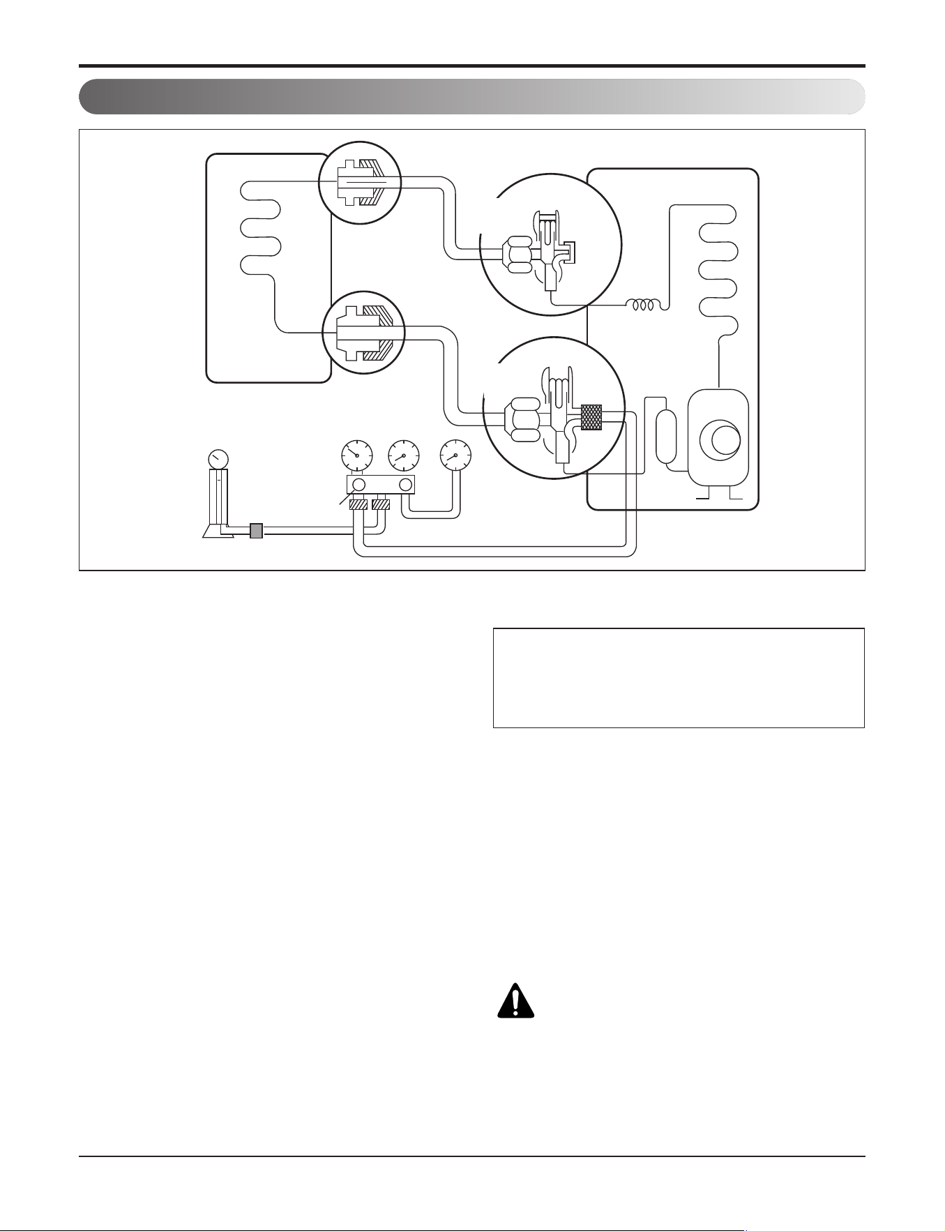
Part 5. Trouble Shooting
- 46 -
Copyright ©2017 LG Electronics. Inc. All right reserved.
Only for training and service purposes
LGE Internal Use Only
Lo
Charging
cylinder
Outdoor unit
Indoor unit
Liquid side
Gas side
Open
3-Way
valve
3-Way
valve
OPEN
Open
Check valve
(1)
Vacuum
Gage
• Procedure
(1) Connect the charge hose to the charging
cylinder.
– Connect the charge hose which you dis-con-
nected from the vacuum pump to the valve at
the bottom of the cylinder.
– If you are using a gas cylinder, also use a scale
and reverse the cylinder so that the system can
be charged with liquid.
(2) Purge the air from the charge hose.
– Open the valve at the bottom of the cylinder
and press the check valve on the charge set to
purge the air. (Be careful of the liquid refriger-
ant). The procedure is the same if using a gas
cylinder.
(3) Open the valve (Lo side on the charge set and
charge the system with liquid refrigerant.
– If the system can not be charged with the spec-
ified amount of refrigerant, it can be charged
with a little at a time (approximately 150g each
time) while operating the air conditioner in the
cooling cycle; however, one time is not suffi-
cient, wait approximately 1 minute and then re-
peat the procedure (pumping down-pin).
(4) Immediately disconnect the charge hose from
the 3-way valve’s service port.
–
Stopping partway will allow the gas to be discharged.
–
If the system has been charged with liquid refrig-
erant while operating the air conditioner turn off
the air conditioner before disconnecting the hose.
(5)
Mount the valve stem nuts and the service port nut.
– Use torque wrench to tighten the service port
nut to a torque of 1.8 kg.m.
– Be sure to check for gas leakage.
WARNING
When installing or relocation the unit, make sure
that no substance other than the specified refriger-
ant(R410A) enter the refrigerant circult.
- Any presence of foreign substance such as air can
cause an abnormal pressure rise and may result in
explosion or injury.
This is different from previous procedures.
Because you are charging with liquid refrigerant
from the gas side, absolutely do not attempt to
charge with larger amounts of liquid refrigerant
while operating the air conditioner.
4. Gas Charging (After Evacuation)
Part 5. Trouble Shooting
- 47 -
Copyright ©2017 LG Electronics. Inc. All right reserved.
Only for training and service purposes
LGE Internal Use Only
Trouble analysis
1. Check temperature difference between intake and discharge air, and check for the operating current too.
Case Symptom Supposed Caused
Temp. difference : approx. 0°C
Current : less than 80% of rated current
Temp. difference : approx. 8°C
Current : less than 80% of rated current
Temp. difference : less than 8°C
Current : over the rated current
Temp. difference : over 8°C
All amount of refrigerant leaked out.
Check refrigeration cycle.
Refrigerant leakage Clog of refrigeration cycle
Defective Compressor.
Excessive amount of refrigerant
Normal
Case 1
Case 2
Case 3
Case 4
Temperature difference between intake and discharge air depends on room air humidity. When the room air humidity is
relativery higher, temperature difference is smaller. When the room air humidity is relatively lower temperature difference
is larger.
2. Check temperature and pressure of refrigeration cycle in cooling mode.
1. The suction pressure is usually 8.5~9.5kg/cm2G(Cooling) at normal condition.(R410A)
2. The temperature can be measured by attaching the thermometer to the low pressure tubing and wrap it with putty.
NOTICE
NOTICE
Suction pressure
(Compared with Cause of Trouble Description
the normal value)
Defective compressor Current is low.
Defective 4-way reverse valve
Excessive amount of High pressure does not quickly
Normal refrigerant rise at the beginning of
operation.
Insufficient amount of Current is low.
Lower Higher refrigerant (Leakage)
Clogging
High
Higher
Temperature of Discharge
Air (Compared with the
normal valve)
5. Cycle Part
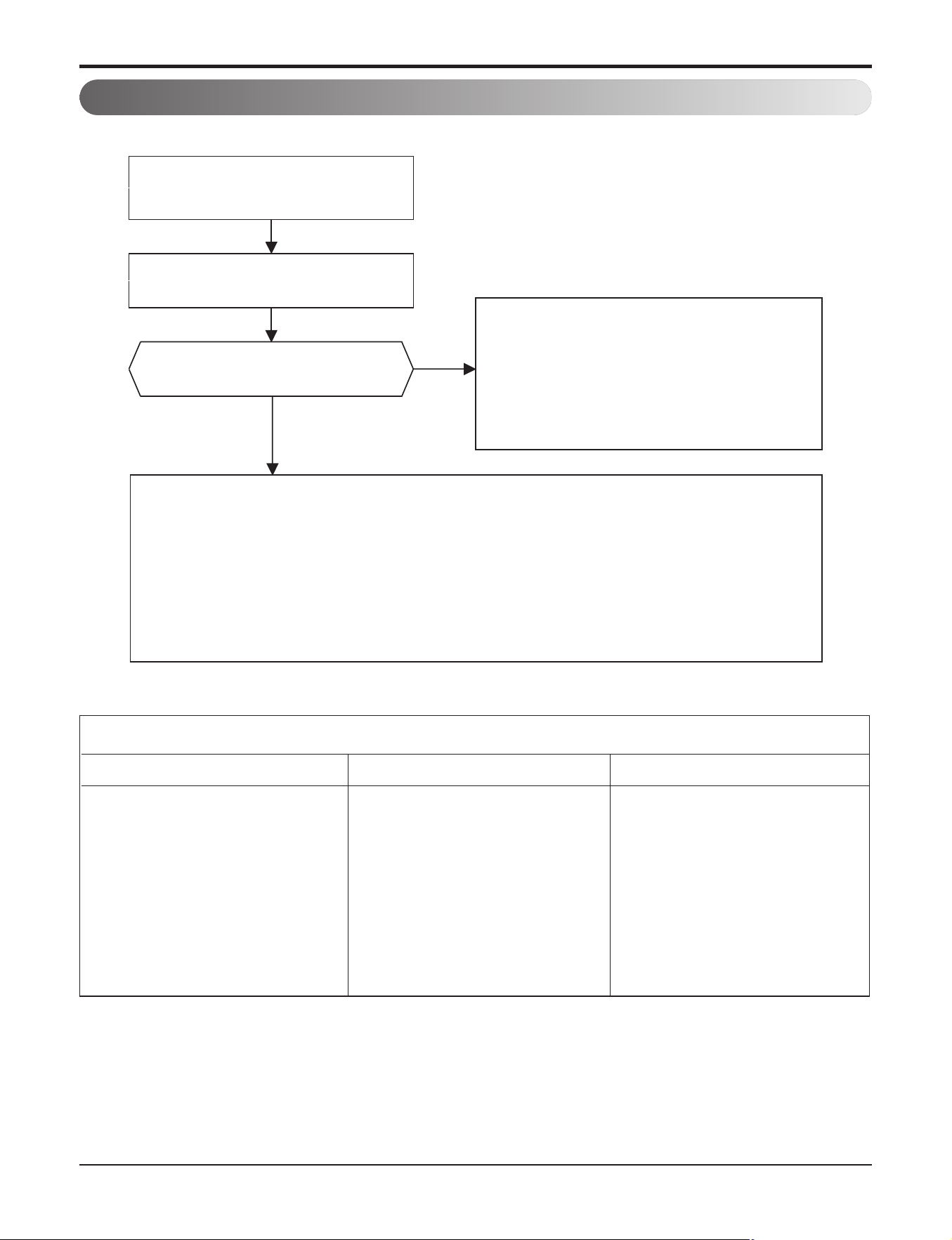
Part 5. Trouble Shooting
- 48 -
Copyright ©2017 LG Electronics. Inc. All right reserved.
Only for training and service purposes
LGE Internal Use Only
6.1 The Product doesn’t operate at all
The operation check of the Indoor PCB Assembly
Procedure
1) The input voltage of power mod-
ule.
2) The output voltage of power mod-
ule.
4) IC04D(7805)
5) IC01A(KIA7036)
Specification
1) AC230V ± 30V
: Check the rated voltage
2) 12V ± 3V
4) DC5V
5) The voltage of micom pin 19
: DC4.5V↑
Remedy
1) Check the power outlet.
2) Replace
PCB Assembly
4) Replace PCB Assembly
5) Replace PCB Assembly
Turn on the main power again.
Turn off the main power and
wait for 10 seconds.
Yes
No
A "Beeping" sound is made
from the indoor unit
Check the voltage of power supply (AC208/230V,60Hz) and check
for the following :
* The voltage of main power supply.
* The voltage applied to the unit.
* The connecting method of Indoor/Outdoor connecting cable (each color)
* The PCB Assembly (Fuse, Noise Filter, Power Module, Bridge Diode, etc.)
Primarily, the operating condition of
Micom is O.K.
* Check, Remote controller & Receiver.
* Check CN-DISP1, CN-DISP2 of
indoor PCB
6. Electronic Parts
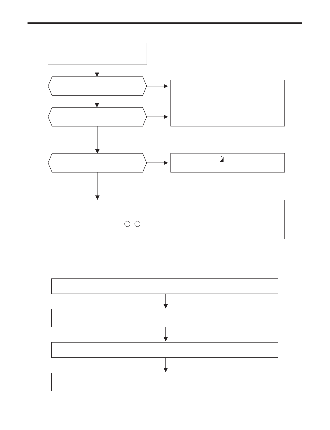
Part 5. Trouble Shooting
- 49 -
Copyright ©2017 LG Electronics. Inc. All right reserved.
Only for training and service purposes
LGE Internal Use Only
Turn on the main power.
When in air circulation mode, compressor/outdoor fan is stopped.
Check the sensor for Indoor temperature is attatched as close as to be effected by the
themperature of Heat Exchange (EVA.)
Operate Cooling Mode by setting the disired temperature of the remote controller is less
than one of the Indoor temperature by 1°C at least.
6.3 The Compressor/Outdoor Fan are don't operate
6.2 The Product doesn't operate with the remote controller
Turn on the main power
Yes
No
A "Beeping" sound is made
from the indoor unit
* Refer to 6.1
* Check the voltage of power
(AC208/230V,60Hz).
Is it possible to turn on the unit
by ON/OFF button on display?
Yes
No
Is the remote controller
working properly?
Yes
* When the mark ( ) is displayed
in LCD screen, replace battery.
No
* Check the contact point of CN-DISP 1, 2 connector & Re connector.
* Check display PCB Assembly
- Voltage between CN-DISP1 - should be DC +5V,
- If problem still persists, Replace display PCB
3 6
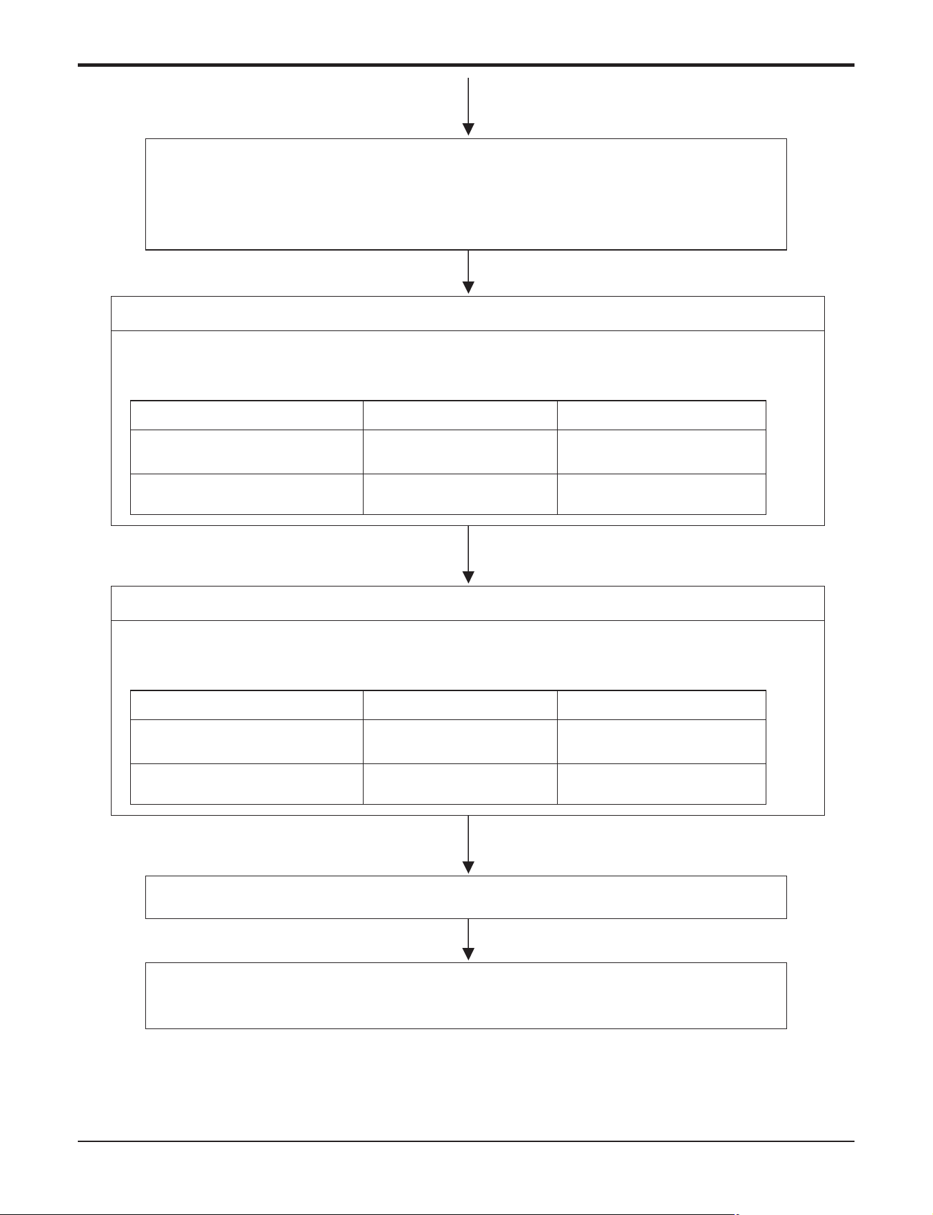
Part 5. Trouble Shooting
- 50 -
Copyright ©2017 LG Electronics. Inc. All right reserved.
Only for training and service purposes
LGE Internal Use Only
Turn off main power.
Check the electrical wiring diagram of Outdoor side.
Check the open or short of connecting wires between Indoor and Outdoor.
When the sensor circuit for Indoor temperature and connector are in bad connection or are
not engaged, Compressor/Outdoor fan is stopped.
• Check the related circuit of R02H(12.1K), R01H(1K), R04H(6.2K), R03H(1K), C01H(102),
C02H(102), Micom(pin No. ⑪, ⑫).
• Check the Indoor temperature sensor is disconnected or not (about 10K at 25°C).
Check the Relay(RY-PWR, RY-START) for driving Compressor.
• Check the voltage between brown and blue cable of terminal to connect the Outdoor
(About AC208/230).
• Check the related circuit of relay in Outdoor PCB Ass'y.
Check Point
Between Micom(No. 19) and
GND
DC 5V DC 0V
DC 12VDC 1V↓
Between IC01M(No. 10) and
GND
Comp. ON Comp. OFF
Check the Relay(RY-PWR, RY-CHARGE) for driving Compressor.
• Check the voltage between brown and blue cable of terminal to connect the Outdoor
(About AC208/230).
• Check the related circuit of relay in Outdoor PCB Ass'y.
Check Point
Between Micom(No. 11) and
GND
DC 5V DC 0V
DC 12VDC 1V↓
Between IC01M(No. 16) and
GND
Comp. ON Comp. OFF
36,42kBtu/h class
18,24,36kBtu/h class
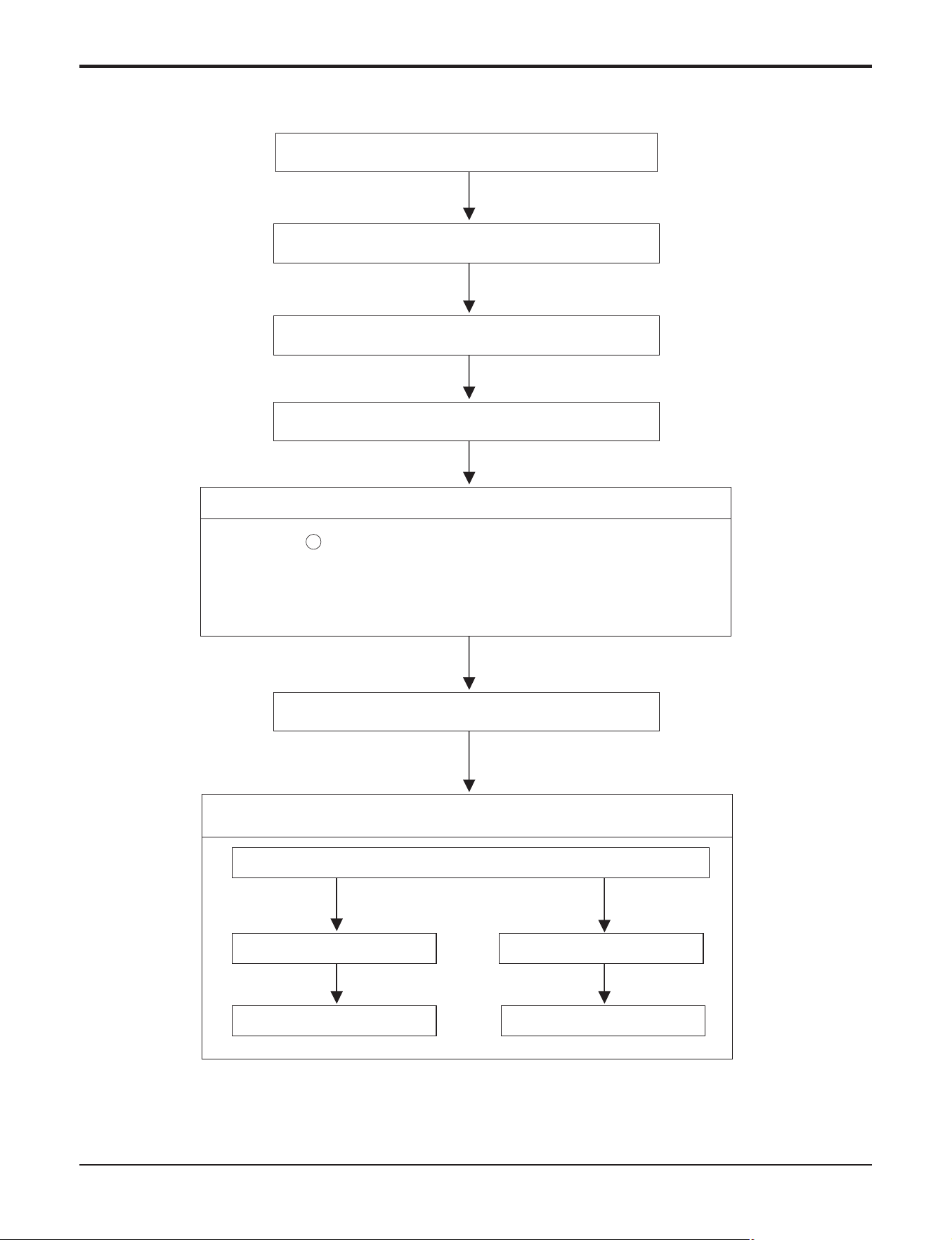
Part 5. Trouble Shooting
- 51 -
Copyright ©2017 LG Electronics. Inc. All right reserved.
Only for training and service purposes
LGE Internal Use Only
6.4 When indoor Fan does not operate.
Check the SSR high speed operation by remote control.
(the Indoor Fan Motor is connected)
Turn off main power.
Check the connection of CN-FAN.
Check the Fan Motor.
Check the Fuse(AC250V, T2A).
Turn on the main power
Check the related circuit of indoor Fan Motor.
• The pin No.
38
of micom and the part for driving SSR.(Q01M)
• Check the related pattern.
• Check the SSR.
- SSR Open: Indoor Fan Motor never operate.
- SSR short: Indoor Fan Motor always operates in case of ON or OFF.
The voltage of Pin No 1(orange) and 3(black) of CN-FAN.
About AC 160V over About AC 50V over
SSR is not damaged Check SSR
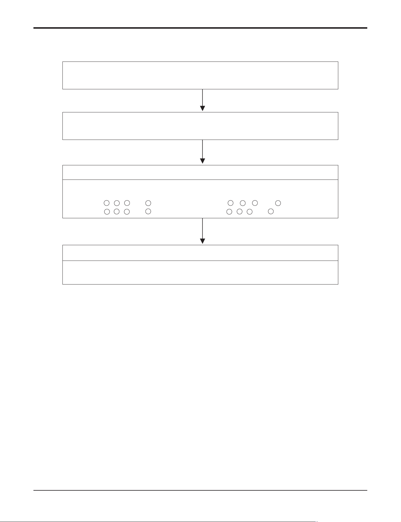
Part 5. Trouble Shooting
- 52 -
Copyright ©2017 LG Electronics. Inc. All right reserved.
Only for training and service purposes
LGE Internal Use Only
• Confirm that the vertical louver is normally geared with the shaft of Stepping Motor.
• If the regular torque is detected when rotating the vertical louver with hands ⇒ Normal
• Check the connecting condition of CN-U/D or CN0L/R Connector
• Check the soldering condition(on PCB) of CN-U/D or CN0L/R Connector
Check the operating circuit of the vertical louver
• Confirm that there is DC +12V between pin ¿ of CN-U/D, CN0L/R and GND.
• Confirm that there is a soldering short at following terminals.
- Between 1 , 2 , 3 and 4 of MICOM - Between
17
,
18
,
19
and
20
of MICOM
- Between 4 , 5 , 6 and 7 of IC01M - Between 5 , 6 , 7 and 8 of IC01M
6.5 When the louver does not operate.
If there are no problems after above checks.
• Confirm the assembly condition that are catching and interfering parts in the link of the
vertical louver
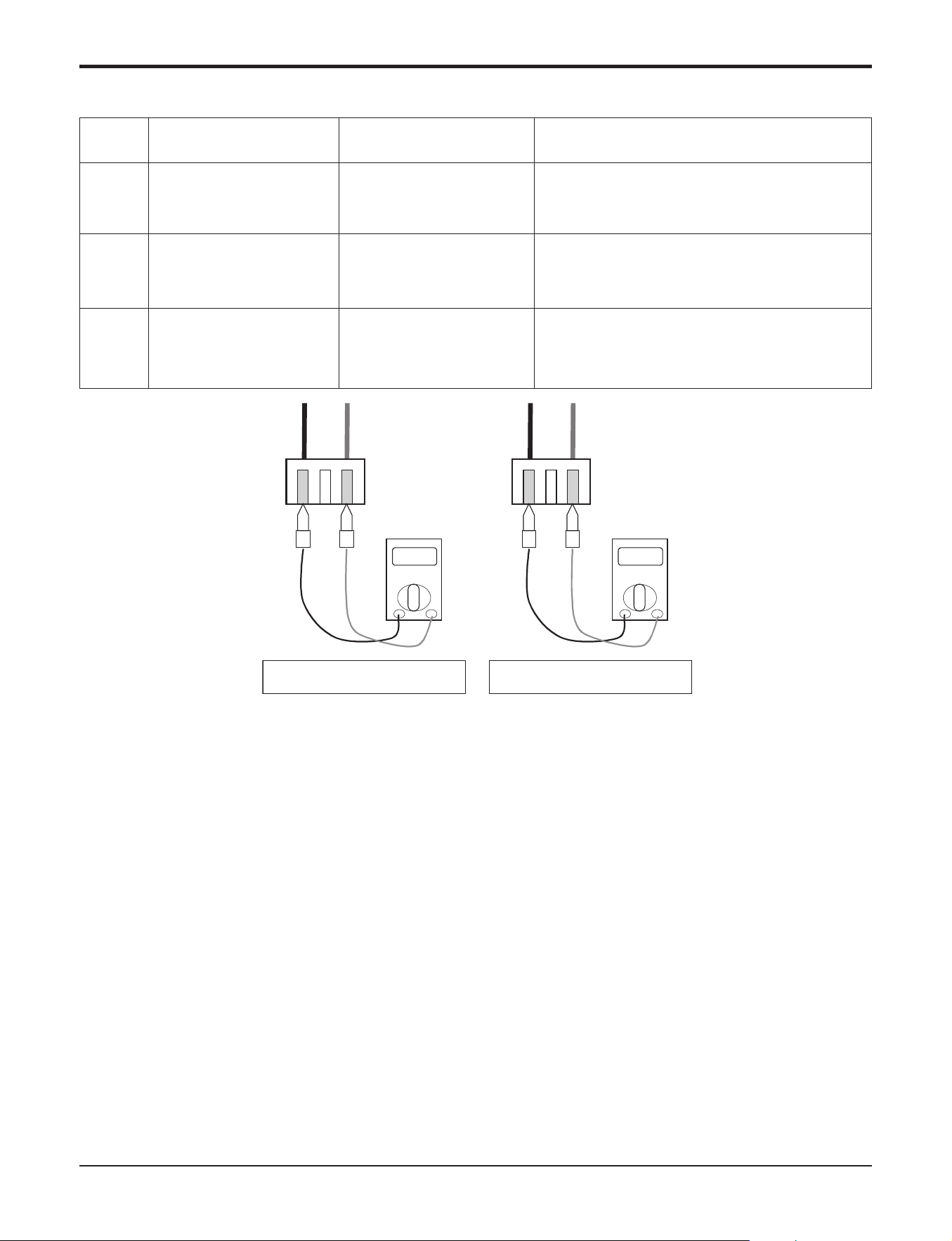
Part 5. Trouble Shooting
- 53 -
Copyright ©2017 LG Electronics. Inc. All right reserved.
Only for training and service purposes
LGE Internal Use Only
Ω
10kΩ
Check the resistance
Check the voltage
V
2.5Vdc
Check Point
1. Unplug the sensor on Indoor unit PCB.
2. Estimate the resistance of each sensor.
3. If the resistance of the sensor is 10KΩ/ 5KΩ at 25°C, then sensor is normal.
4. If the resistance of the sensor is 0 KΩ or ∞, then sensor is abnormal. ’ Change the sensor.
5. Plug the sensor on Indoor unit PCB and Power ON.
6. Estimate the voltage of each sensor.
7. If the voltage of the sensor is 2.5Vdc at 25°C, then sensor is normal.
8. If the resistance of the sensor is 0 or 5Vdc, then sensor is abnormal. ’ Repair or Change the PCB.
6.6 Troubleshooting Indoor Error
01
02
06
Indoor air sensor
Indoor inlet pipe sensor
Indoor outlet pipe sensor
• Open / Short
• Soldered poorly
• Internal circuit error
• Open / Short
• Soldered poorly
• Internal circuit error
• Open / Short
• Soldered poorly
• Internal circuit error
Normal resistor : 10KΩ/ at 25°C (Unplugged)
Normal voltage : DC 2.5V / at 25°C (plugged)
Normal resistor : 5KΩ/ at 25°C (Unplugged)
Normal voltage : DC 2.5V / at 25°C (plugged)
Normal resistor : 5KΩ/ at 25°C (Unplugged)
Normal voltage : DC 2.5V / at 25°C (plugged)
Display
code
Title Cause of error Check point & Normal condition
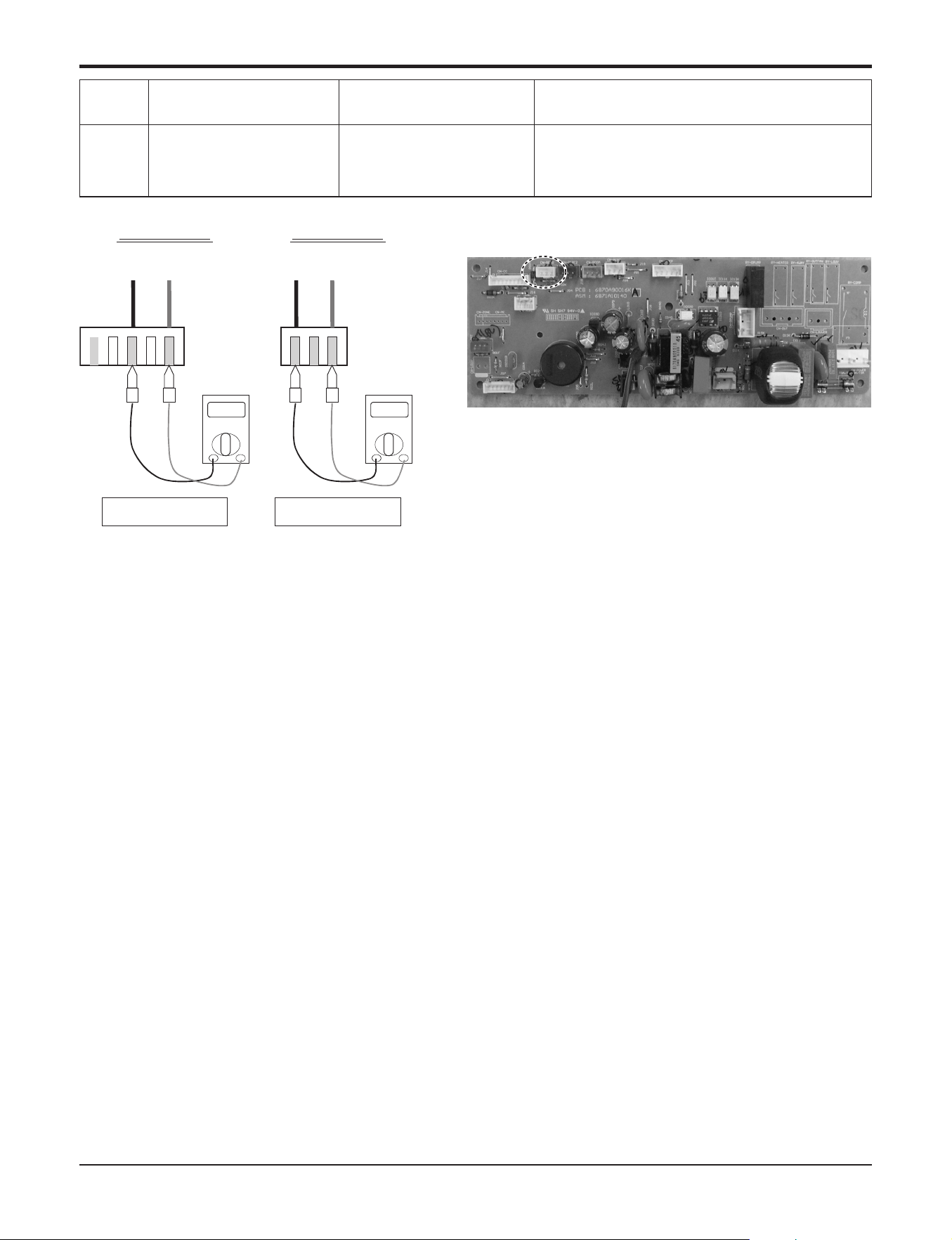
Part 5. Trouble Shooting
- 54 -
Copyright ©2017 LG Electronics. Inc. All right reserved.
Only for training and service purposes
LGE Internal Use Only
Check the Volt.
Indoor Unit
V
12Vdc
12V S GND
Check the Volt.
Wired R/C
V
12Vdc
12V S GND
CN-REMO
Check Point
1. Check the wire connection. (Open / Short) ’ Repair the connection
2. Check the soldering state of connector. (Soldered poorly) ’ Repair or Change the PCB.
3. Check the volt. Of main PCB power source. (DC 12V) ’ Repair or Change the main PCB.
4. Check the installation of wired remote controller. (Noise interference) ’ Adjust the state of installation
03
Communication
Wired R/C
• Open / Short
• Wrong connection
• Connection of wire
• Main PCB Volt. DC12V
• Noise interference
Display
code
Title Cause of error Check point & Normal condition
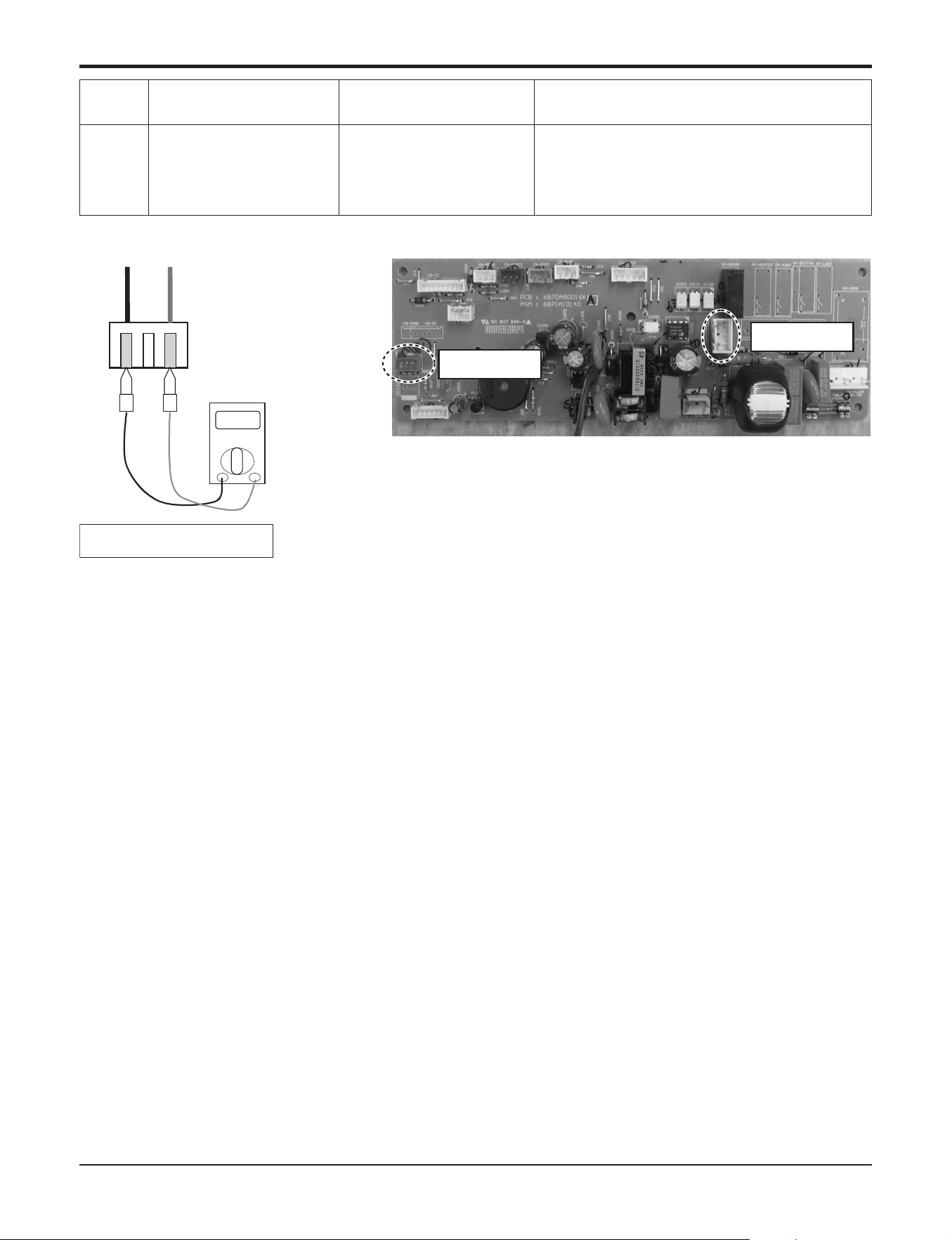
Part 5. Trouble Shooting
- 55 -
Copyright ©2017 LG Electronics. Inc. All right reserved.
Only for training and service purposes
LGE Internal Use Only
Check the resistance
Ω
0Ω
CN Float
CN-Float
CN-D/PUMP
04
Drain pump
/ Float switch
• Float switch Open.
(Normal : short)
• The connection of wire(Drain pump/ Float switch)
• Drain pump power input. (230V)
• Drain tube installation.
• Indoor unit installation. (Inclination)
Display
code
Title Cause of error Check point & Normal condition
Check Point
1. Check the wire connection. (Open, Soldered poorly) ’ Repair the connection or change the PCB.
2. Check the resistance of float switch (Abnormal : Open, Normal : short) ’ Check the float switch.
3. Check the level of water
4. Check the volt. Of Drain pump power supply. (AC 230V) ’ Repair or Change the main PCB.
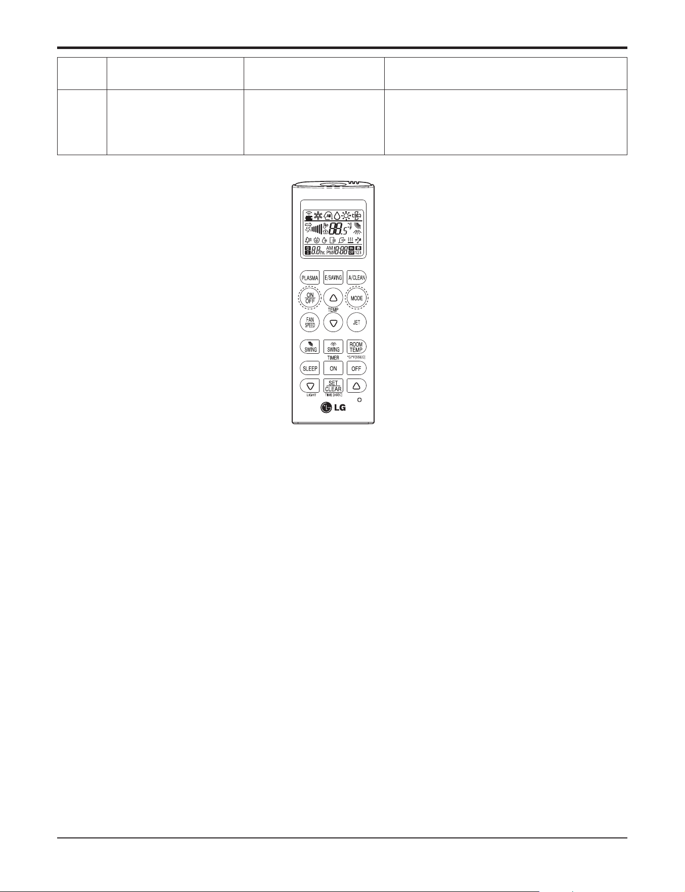
Part 5. Trouble Shooting
- 56 -
Copyright ©2017 LG Electronics. Inc. All right reserved.
Only for training and service purposes
LGE Internal Use Only
07
Different Operation Mode
• One of Indoor Unit oper-
ate cooling Another Unit
operate heating
• At the same time, this model cannot use cool and
heating mode
Display
code
Title Cause of error Check point & Normal condition
Check Point
1. Check another indoor model operation mode
2. Operating the same mode with the first operated indoor unit
3. Clearing the "CH07"
Press the on/off button or mode change button and matching the indoor unit mode same as the first operated
indoor unit
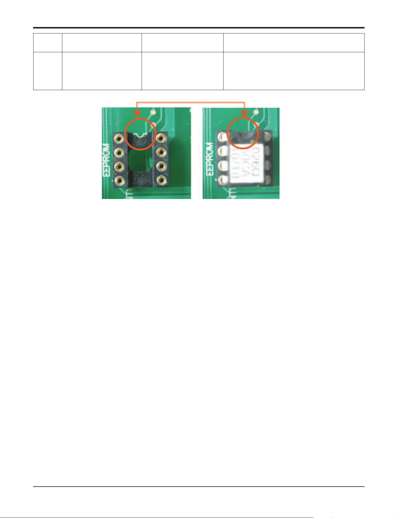
Part 5. Trouble Shooting
- 57 -
Copyright ©2017 LG Electronics. Inc. All right reserved.
Only for training and service purposes
LGE Internal Use Only
09
Indoor EEPROM Check
Sum Error
• Check sum error
1. Check the poor soldering
2. Check the insertion condition of the EEPROM
3. Check the PCB Connection
Display
code
Title Cause of error Check point & Normal condition
Check Point
1. Check the EEPROM Direction
2. If the EEPROM value & the Program value are not matched, the Code is Displayed
3. After Checking the connection and Insertion, replace the PCB or Option PCB
<EEPROM Direction Check Point>
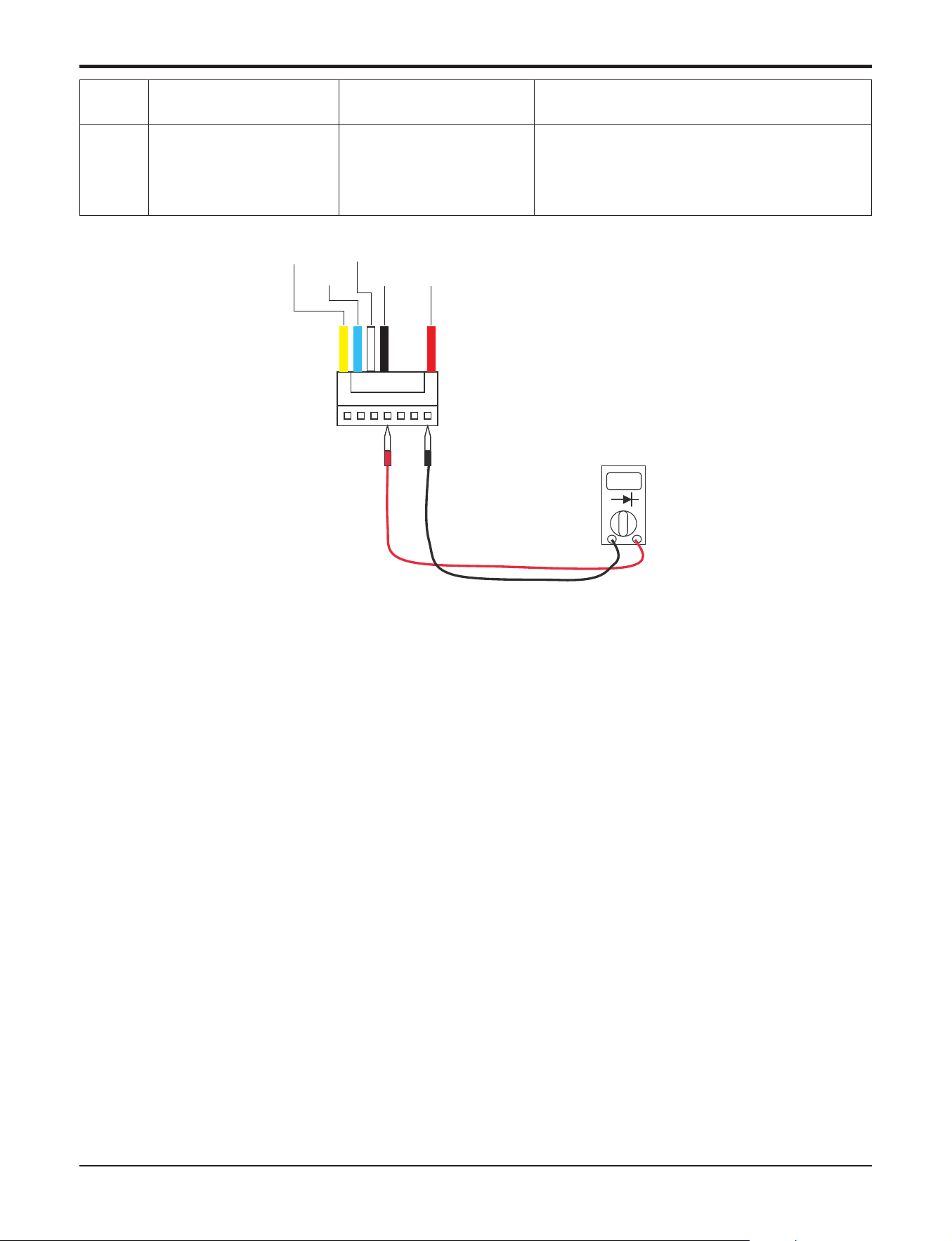
Part 5. Trouble Shooting
- 58 -
Copyright ©2017 LG Electronics. Inc. All right reserved.
Only for training and service purposes
LGE Internal Use Only
10
Indoor BLDC Fan Motor
Lock
The Fan is not operated
properly
Check the Indoor fan locking
Display
code
Title Cause of error Check point & Normal condition
Check Point
Check the PCB during the Power on
1. Check the Voltage Red line to Black line
’ The Voltage is about [input voltage x 1.414]
’ if the Voltage does not come with the above Voltage,
’ Check the power input
’ Replace the PCB & Motor
2. Check the Voltage Black line to White
’ the Voltage is DC 15V
’ Check the Power input
’ Replace the motor
Check the Motor
1. Check the shaft
’ if the shaft is not turn smoothly, the Motor Power IC is defected
’ replace the motor
2. Check the motor resistance(if the shaft is turn smoothly, check the resistance)
’ Check Red line to Black line, Blue line to Black line
’ The resistance should infinite
’ replace the motor
Tester
Fan motor
connector
Yellow
Blue
White
Black
Red
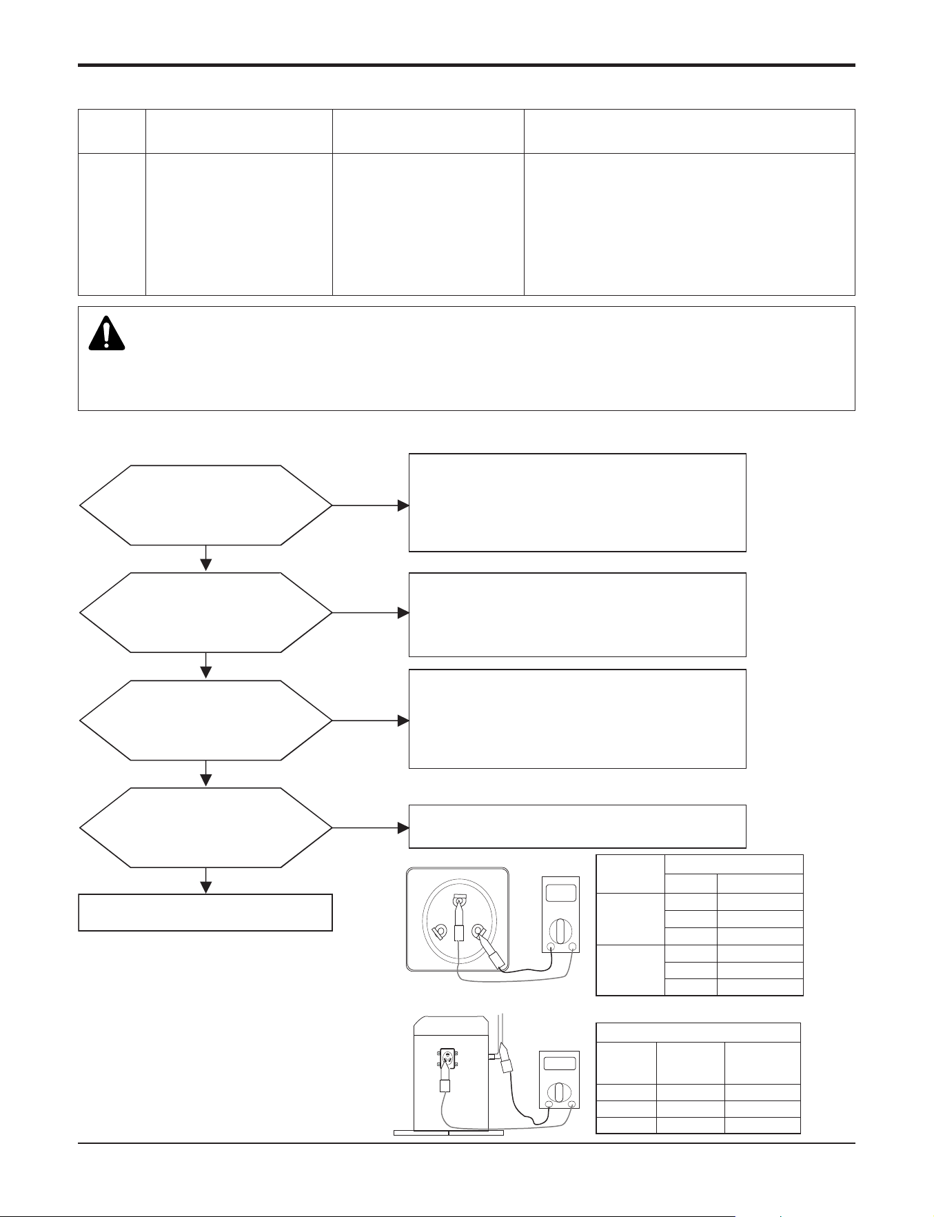
6.7 Troubleshooting Outdoor Error
Part 5. Trouble Shooting
- 59 -
Copyright ©2017 LG Electronics. Inc. All right reserved.
Only for training and service purposes
LGE Internal Use Only
21
DC PEAK
(IPM Fault)
• Instant over current
• Over Rated current
• Poor insulation of IPM
• An instant over current in the U,V,W phase
- Comp lock
- The abnormal connection of U,V,W
• Over load condition
- Overcharging of refrigerant Pipe length.
Outdoor Fan is stop
• Poor insulation of compressor
Display
code
Title Cause of error Check point & Normal condition
Is installation
condition normal?
No
Yes
Yes
Recheck power and installation condition
1. Check Pipe clogging/distortion
2. Check Covering (Indoor/Outdoor Unit)
3. Check EEV connector assemble condition/normal
operation
4. Check refrigerant pressure
→ Reassemble or manage if abnormality found
1. Check resistance between each terminal of compressor
(0.438~0.628±7%)
2. Check insulation resistance between compressor
terminal and pipe (over 2MΩ)
→ Replace compressor if abnormality found
Are the resistance
Between each phase and
insulation resistance of Inverter
compressor normal?
No
Yes
1. Check inverter PCB assembly U,V,W connector
connection condition
2. Check wire disconnection and wiring
3. Check compressor terminal connection condition
(bad contact)
→ Reassemble if abnormality found
Is compressor
Wire connection
condition normal?
No
Yes
Check inverter PCB assembly IPM normality
→ Replace inverter PCB assembly
Is inverter PCB assembly normal?
No
n Error Diagnosis and Countermeasure Flow Chart
n Comp checking method
Comp
Copper
pipe
Model
Resistance(Ω)
Resistance(Ω) at 20°C
18,24,30
kBtu/h class
36,42k
Btu/h class
Terminal
V-W
Inverter Comp.
0.628(at 25˚C)
W-U
0.628(at 25˚C)
U-V
V-W
W-U
U-V
0.628(at 25˚C)
0.438(at 25˚C)
0.438(at 25˚C)
0.438(at 25˚C)
2MΩ
2MΩ
2MΩ
Inverter
comp.
V-GND
W-GND
U-GND
Terminal
2MΩ
2MΩ
2MΩ
Constant
comp.
V
U
W
Comp
WARNING
Before checking PCB or each outdoor electric parts, wait for 3 minutes after the power is off. When measuring at standby state
of power supply, after checking the measurement mode of the meter, be careful of the short-circuits with other parts.
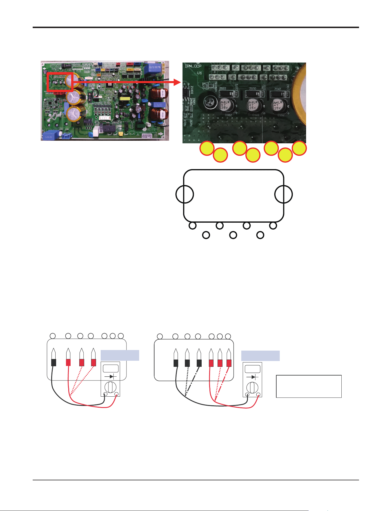
Part 5. Trouble Shooting
- 60 -
Copyright ©2017 LG Electronics. Inc. All right reserved.
Only for training and service purposes
LGE Internal Use Only
▶18,24,30kBtu/h class
25 26 27 29
30
32
33
P
W V U
NwNvNu
33
32
30
29
27
26
25
U1
IPM Check Point
1. Wait until inverter PCB DC voltage is discharged after main power off.
2. Pull out V, V, W COMP connector.
3. Set multi tester to resistance mode.
4.
If the value between P and N terminal of IPM is short(0Ω) or open(hundreds MΩ), PCB needs to be replaced.(IPM damaged)
5. Set the multi tester to diode mode.
6. In case measured value is different from the table, PCB needs to be replaced.(PCB damaged).
27 26 25 24 23 22 21
P U V W Nu Nv Nw
0.4 ~ 0.6 V
27 26 25 24 23 22 21
P U V W Nu Nv Nw
0.4 ~ 0.6 V
PFC_IPM check
U, V, W ‘ R S T
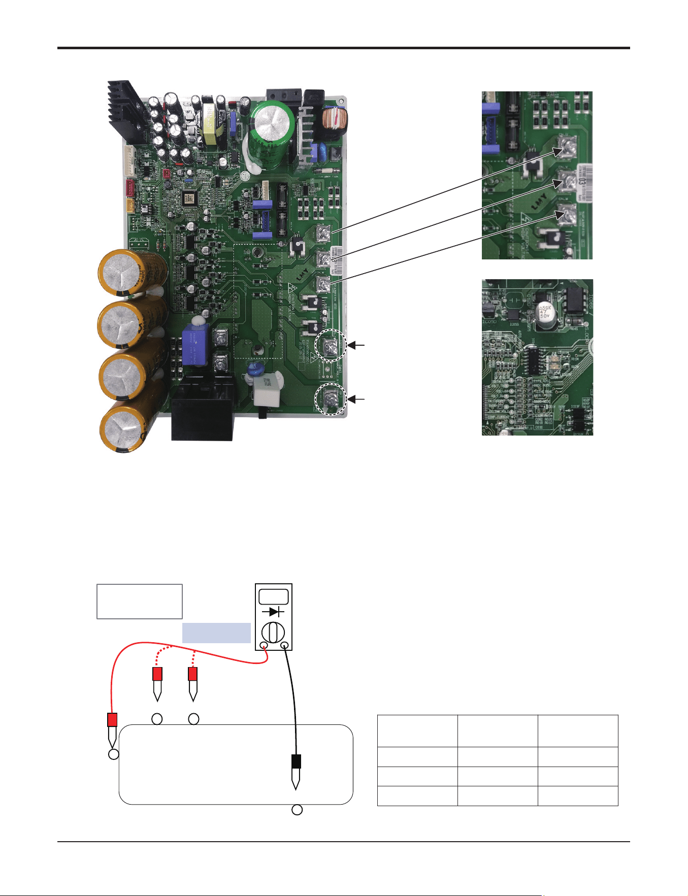
Part 5. Trouble Shooting
- 61 -
Copyright ©2017 LG Electronics. Inc. All right reserved.
Only for training and service purposes
LGE Internal Use Only
CN_INPUT_VOLT_N (BL)
CN_INPUT_VOLT_L (BR)
U
V
W
1. Wait until inverter PCB DC voltage is discharged after main power off.
2. Pull out CN(L), CN(N) connectors and U,V,W COMP Connector.
3. Set multi tester to resistance mode.
4.
If the value between P and N terminal of IPM is short(0Ω) or open(hundreds MΩ), PCB needs to be replaced.(IPM damaged)
5. Set the multi tester to diode mode.
6. In case measured value is different from the table, PCB needs to be replaced.(PCB damaged).
0.3 ~ 0.5 V
Black
Red
25-26
P
W
V
U
ں
ڹ
ڸ
13-15
11-12 8-9
IGBTM check
U, V, W
▶36,42kBtu/h class
Sequence of
Measurement
Measurement
Normal
Standards
1 P-U 0.3V~0.5V
2 P-V 0.3V~0.5V
3 P-W 0.3V~0.5V
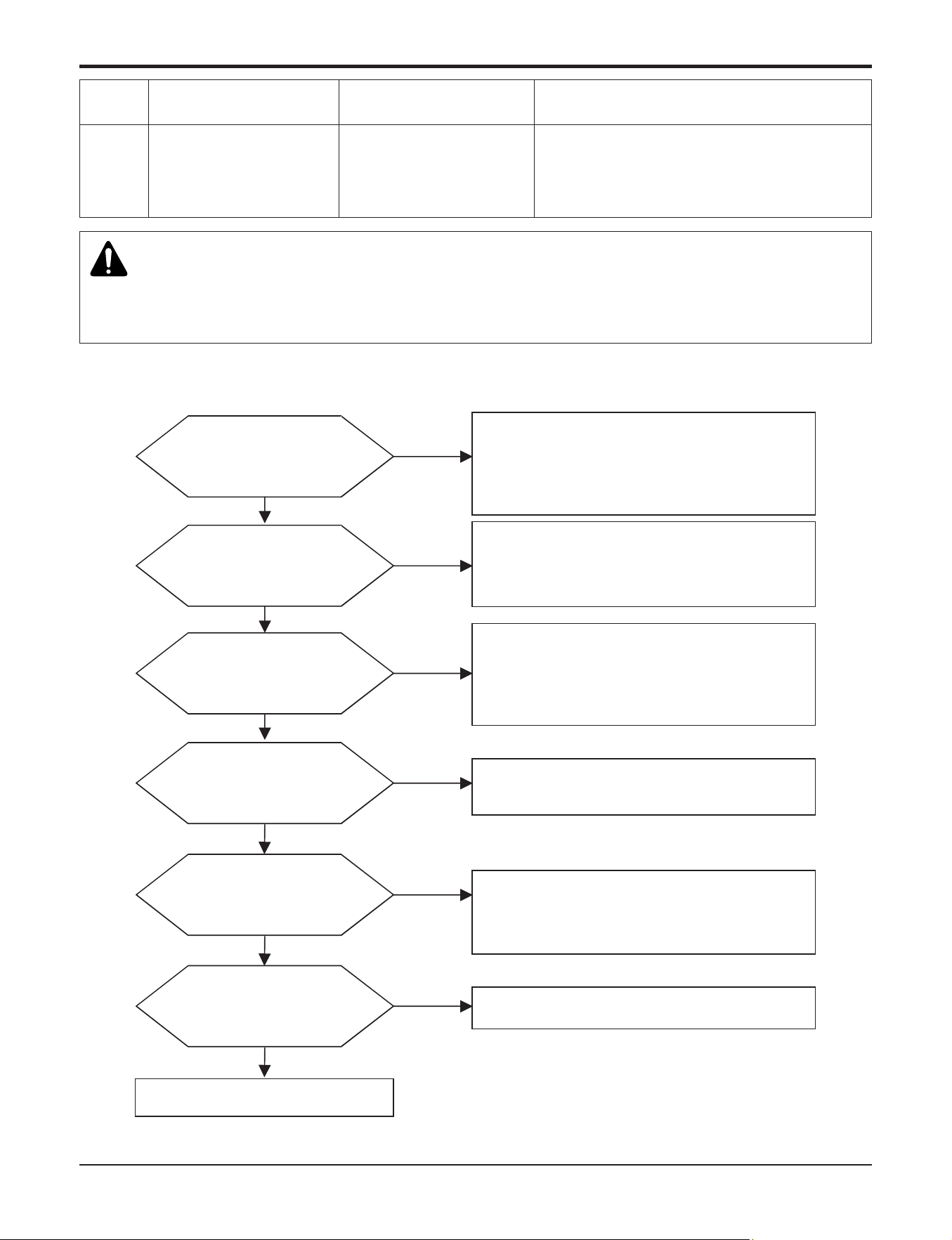
Part 5. Trouble Shooting
- 62 -
Copyright ©2017 LG Electronics. Inc. All right reserved.
Only for training and service purposes
LGE Internal Use Only
22
Max. C/T
Input over current
(18,24,30kBtu/h class 19A↑
36,42kBtu/h class 37A ↑)
1. Malfunction of Compressor
2. Blocking of Pipe
3. Low Voltage Input
4. Refrigerant, Pipe length, Blocked...
Display
code
Title Cause of error Check point & Normal condition
n Error Diagnosis and Countermeasure Flow Chart
Is installation
condition normal?
No
Yes
Yes
Yes
Recheck power and installation condition
Yes
1. Check Pipe clogging/distortion
2. Check Covering (Indoor/Outdoor Unit)
3. Check EEV connector assemble condition/normal
operation
4. Check refrigerant pressure
→ Reassemble or manage if abnormality found
Is inverter PCB assembly
power connection normal?
No
Check connection between inverter PCB assembly and
bridge diode(misconnection, disconnection)
→ wiring again if abnormality found
Yes
Is input voltage normal?
No
Check
L1~L2 phase is 230V 15%
→ Check connection condition and wiring if power is
abnormal
Yes
Is inverter PCB assembly
normal?
No
Check inverter PCB assembly IPM normality
→ Replace inverter PCB assembly
Are the resistance
Between each phase and
insulation resistance of Inverter
compressor normal?
No
1. Check resistance between each terminal of compressor
(0.438~0.628±7%)
2. Check insulation resistance between compressor
terminal and pipe (over 2MΩ)
→ Replace compressor if abnormality found
Is compressor
Wire connection
condition normal?
No
1. Check inverter PCB assembly U,V,W connector
connection condition
2. Check wire disconnection and wiring
3. Check compressor terminal connection condition
(bad contact)
→ Reassemble if abnormality found
WARNING
Before checking PCB or each outdoor electric parts, wait for 3 minutes after the power is off. When measuring at standby state
of power supply, after checking the measurement mode of the meter, be careful of the short-circuits with other parts.
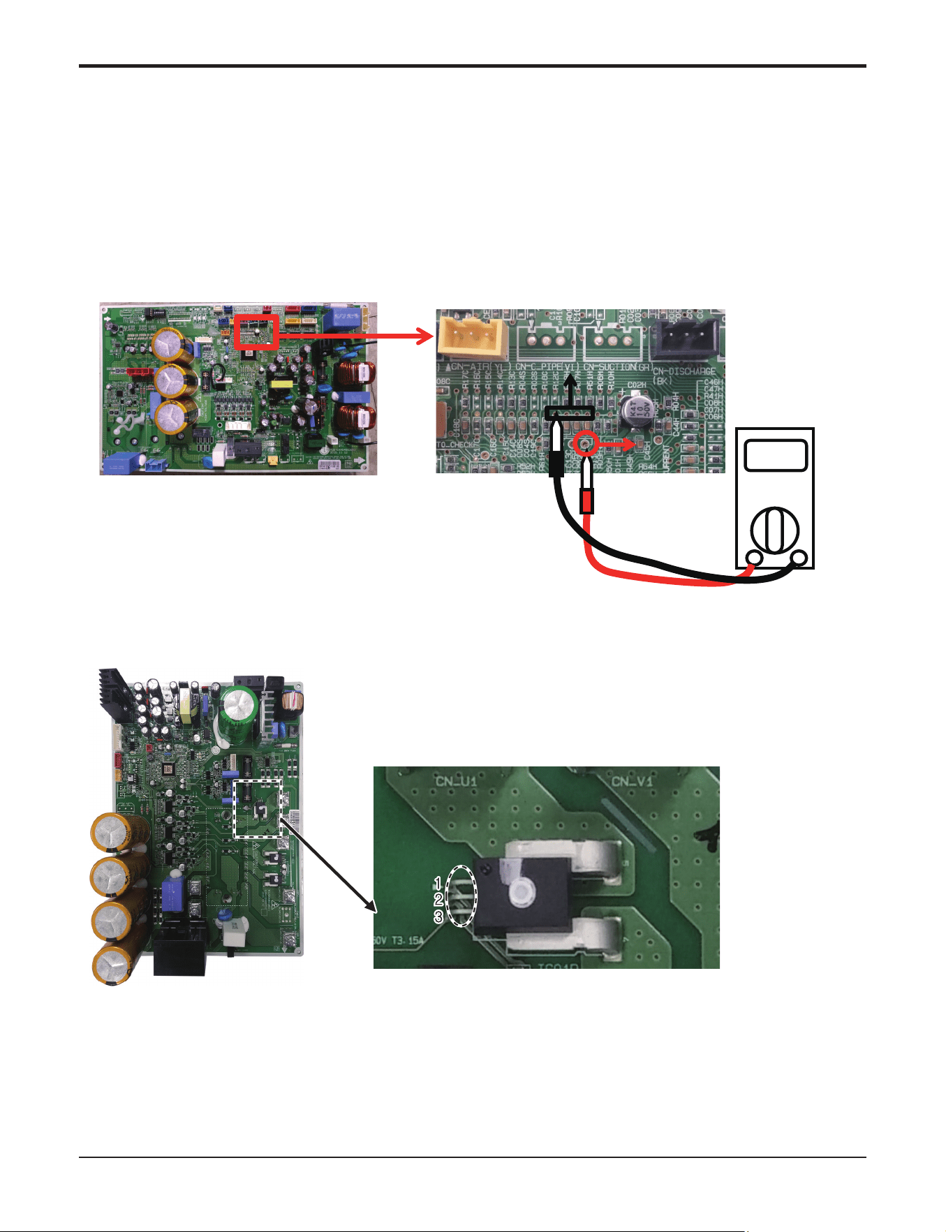
Part 5. Trouble Shooting
- 63 -
Copyright ©2017 LG Electronics. Inc. All right reserved.
Only for training and service purposes
LGE Internal Use Only
Check Point
1. Check the power source.(230V ±15%)
2. Check the fan operation is right.
3. Check the current.
4. Check the install condition.
5. Check the CT Sensor Output signal
(18/24/30 kBtu/h class - Check output the CT Sensor : DC 2.5±0.2V)
(36/42 kBtu/h class - Check output pin 1.2 of the CT Sensor : 5V )
Vdc
2.5V
I_INI_IN
GNDGND
Red
Black
<CT Sensing Check Point>< Inverter PCB>
▶36,42kBtu/h class
▶18,24,30kBtu/h class
Part 5. Trouble Shooting
- 64 -
Copyright ©2017 LG Electronics. Inc. All right reserved.
Only for training and service purposes
LGE Internal Use Only
23
DC Link High / Low Volt
• DC Link Voltage is
above 420Vdc
• DC Link Voltage is
below 140Vdc
• Check CN_(L), CN_(N) Connection
• Check Input Voltage
• Check PCB DC Link voltage sensor parts
Display
code
Title Cause of error Check point & Normal condition
n Error Diagnosis and Countermeasure Flow Chart
Is Inverter PCB assembly
Power connection normal?
No
Check connection from terminal block to
Inverter PCB assembly CN(L), CN(N)
Yes
Is input voltage normal ?
No
Yes
Is Inverter PCB Normal?
No
Replace inverter PCB assembly
Recheck power and installation
condition
Yes
Check L1~L2 Voltage is 230V±15%
WARNING
Before checking PCB or each outdoor electric parts, wait for 3 minutes after the power is off. When measuring at standby state
of power supply, after checking the measurement mode of the meter, be careful of the short-circuits with other parts.
Part 5. Trouble Shooting
- 65 -
Copyright ©2017 LG Electronics. Inc. All right reserved.
Only for training and service purposes
LGE Internal Use Only
Check Point
1. Check the REACTOR_IN and REACTOR_OUT1,2 Connection condition at the Main PCB.(Refer to outdoor
wiring diagram)
2. Measure the voltage as shown in figures.
3. If the measurements are significantly different from the levels shown in the figures, the PFCM is deemed to be
damaged.
IN
OUT
OUT
Red
Black
Vdc
Sequence of
Measurement
Measurement
Normal
Standards
Sequence of
Measurement
Measurement
Normal
Standards
1 C – E 0.3V~0.5V
2 C – E 0.3V~0.5V
ڹ
ڸ
0.3 ~ 0.5 V
< IGBT >
ڸ
ڹ
ڸ
ڹ
C : Collector / E : Emitter
1 A – C 0.3V~0.5V
2 A – C 0.3V~0.5V
< FRD >
A : Anode / C : Cathode
ڸ
ڹ
IGBT IGBT FRD
▶18,24,30kBtu/h class
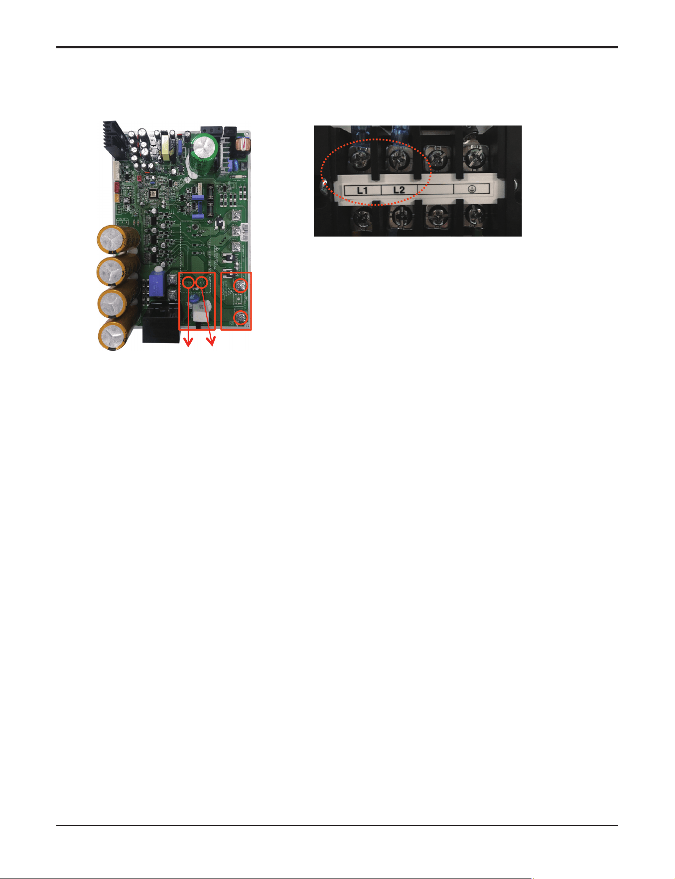
Part 5. Trouble Shooting
- 66 -
Copyright ©2017 LG Electronics. Inc. All right reserved.
Only for training and service purposes
LGE Internal Use Only
* Measuring input voltage
N
L
<Inverter PCB>
(+) (-)
▶36,42kBtu/h class
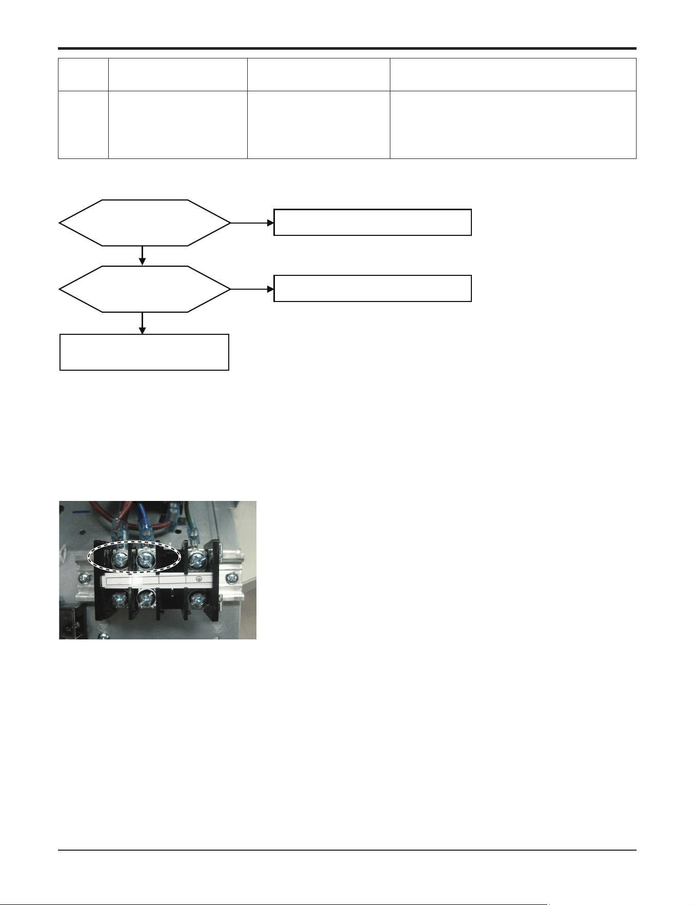
Part 5. Trouble Shooting
- 67 -
Copyright ©2017 LG Electronics. Inc. All right reserved.
Only for training and service purposes
LGE Internal Use Only
Check Point
1. Check the Input Voltage (L1~L2 ‘ 230V±10%)
2. Check Input Voltage Sensor output voltage (2.5Vdc±10%)
25
Input voltage
• Abnormal Input voltage
(140Vac , 300Vac)
• Check the power source.
• Check the components.
Display
code
Title Cause of error Check point & Normal condition
Is Inverter PCB Normal?
No
Replace inverter PCB assembly
Is input voltage normal ?
No
Check L1~L2 Voltage is 230V±15%
Yes
Recheck power and
installation condition
Yes
< Input Power Source Check Point >
L1
L2
n Error Diagnosis and Countermeasure Flow Chart
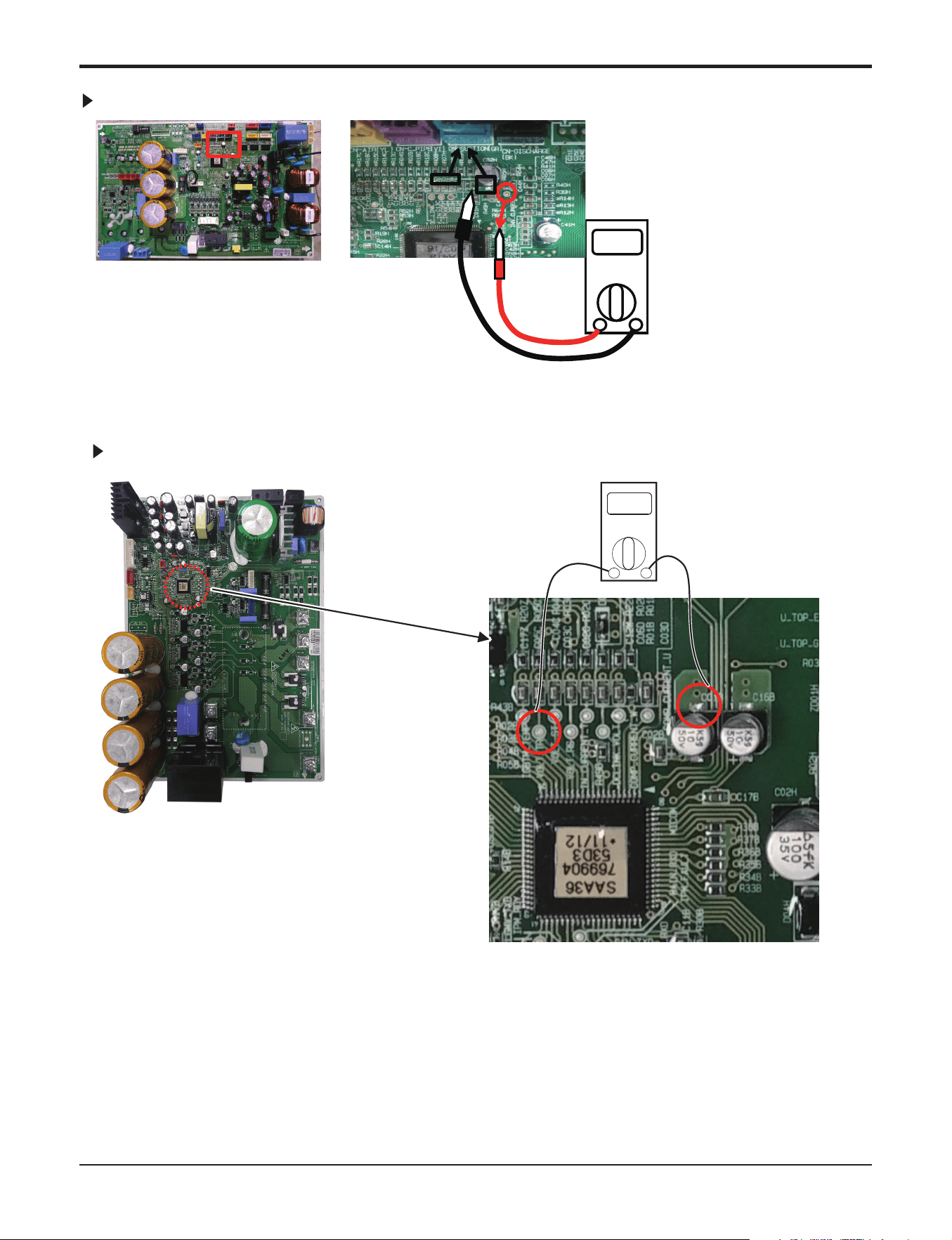
Part 5. Trouble Shooting
- 68 -
Copyright ©2017 LG Electronics. Inc. All right reserved.
Only for training and service purposes
LGE Internal Use Only
<CT Sensing Check Point>
18,24,30kBtu/h class
Vdc
2.5V
GND
Red
Black
INV_CurINV_CurrententINV_Current
GNDGND
INPUT(V)INPUT(V) INPUT(V)
GND
< Inverter PCB>
< Input Voltage Sensing Check Point >
36,42kBtu/h class
Vdc
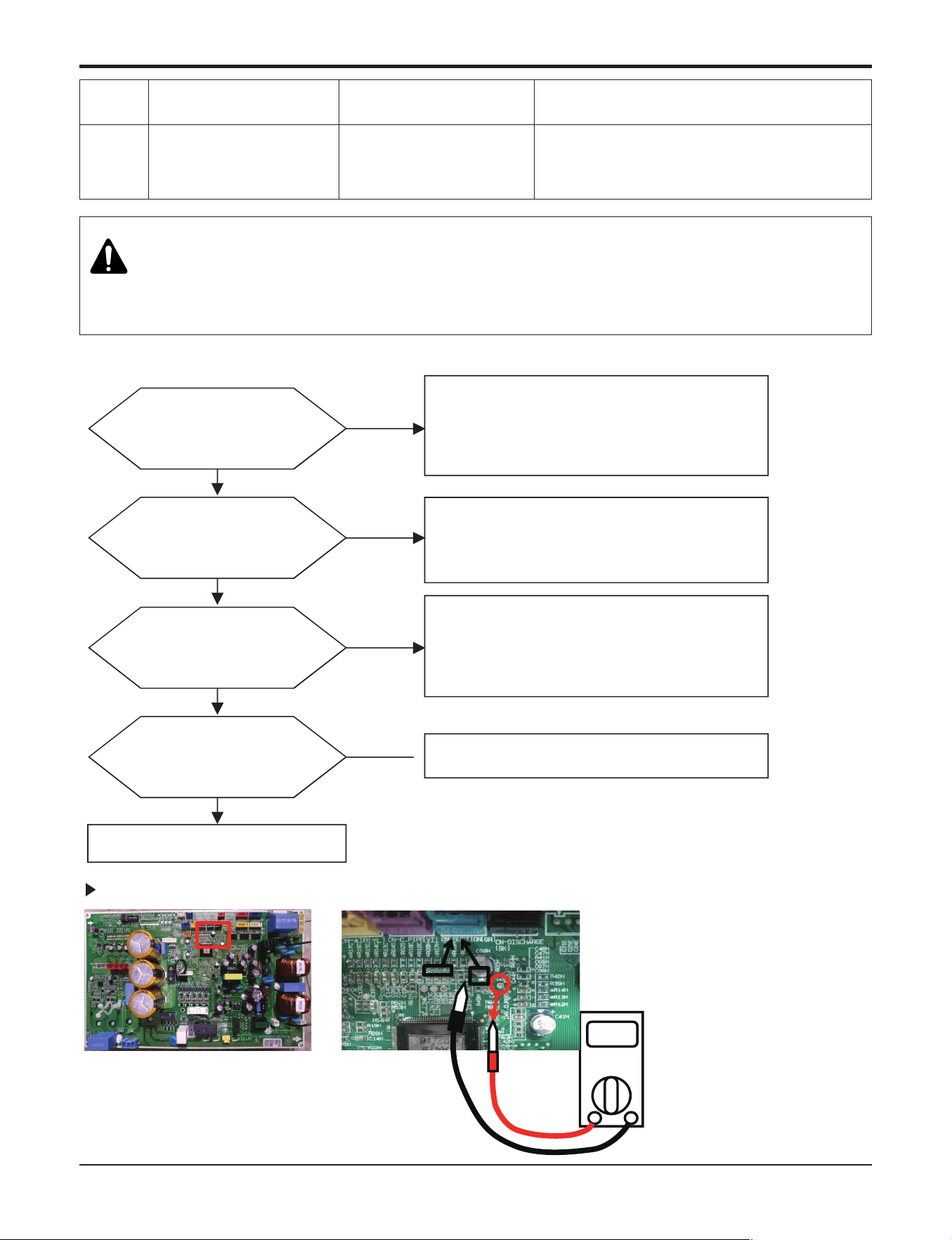
Part 5. Trouble Shooting
- 69 -
Copyright ©2017 LG Electronics. Inc. All right reserved.
Only for training and service purposes
LGE Internal Use Only
26
DC Compressor
Position
• Compressor
Starting fail error
• Check the connection of comp wire “U,V,W”
• Malfunction of compressor
• Check the component of “IPM”, detection parts.
Display
code
Title Cause of error Check point & Normal condition
Is installation
condition normal?
No
Yes
Yes
Recheck power and installation condition
1. Check Pipe clogging/distortion
2. Check Covering (Indoor/Outdoor Unit)
3. Check EEV connector assemble condition/normal
operation
4. Check refrigerant pressure
→ Reassemble or manage if abnormality found
1. Check resistance between each terminal of compressor
(0.438~0.628±7%)
2. Check insulation resistance between compressor
terminal and pipe (over 2MΩ)
→ Replace compressor if abnormality found
Are the resistance
Between each phase and
insulation resistance of Inverter
compressor normal?
No
Yes
1. Check inverter PCB assembly U,V,W connector
connection condition
2. Check wire disconnection and wiring
3. Check compressor terminal connection condition
(bad contact)
→ Reassemble if abnormality found
Is compressor
Wire connection
condition normal?
No
Yes
Check inverter PCB assembly IPM normality
→ Replace inverter PCB assembly
Is inverter PCB assembly normal?
No
18,24,30kBtu/h class
Vdc
2.5V
GND
Red
Black
INV_CurINV_CurrententINV_Current
WARNING
Before checking PCB or each outdoor electric parts, wait for 3 minutes after the power is off. When measuring at standby state
of power supply, after checking the measurement mode of the meter, be careful of the short-circuits with other parts.
n Error Diagnosis and Countermeasure Flow Chart
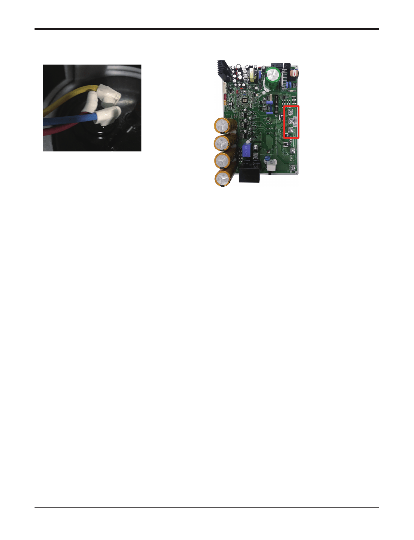
Part 5. Trouble Shooting
- 70 -
Copyright ©2017 LG Electronics. Inc. All right reserved.
Only for training and service purposes
LGE Internal Use Only
* Measuring resistance between each terminal of compressor
* Compressor wire connection
U
V
W
ȯ36,42kBtu/h class
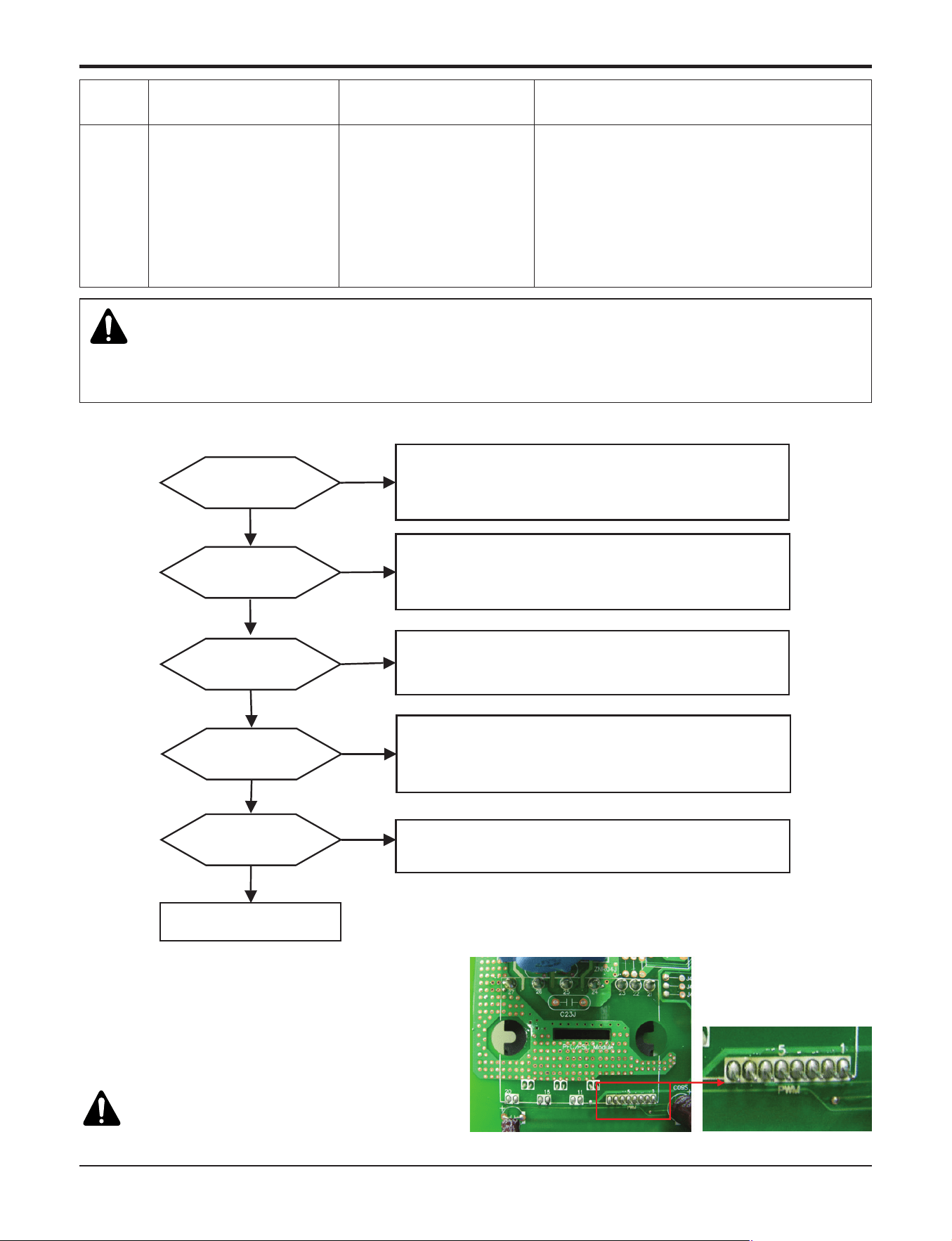
Part 5. Trouble Shooting
- 71 -
Copyright ©2017 LG Electronics. Inc. All right reserved.
Only for training and service purposes
LGE Internal Use Only
27
AC Input Instant over
Current Error
Inverter PCB input
current is over100A(peak)
for 2us
1. Overload operation (Pipe clogging/Covering/EEV
defect/Ref. overcharge)
2. Compressor damage (Insulation damage/Motor
damage)
3. Input voltage abnormal (L1,L2)
4. Power line assemble condition abnormal
5. Inverter PCB assembly Damage (input current
sensing part)
Display
code
Title Cause of error Check point & Normal condition
h PFCM Moudle checking method
① Set the multi tester to diode mode.
② Check short between input signal pin which are
placed below PFC Module.
③ Replace PCB assembly if it is short between pins
except No.4,5 pins.
CAUTION
PFCM module No.4,5 pins are internal short state.
No
1.Check Pipe clogging/distortion
2.Check Covering (Indoor/Outdoor Unit)
3.Check EEV connector assemble condition/normal operation
4.Check refrigerant pressure
→ Reassemble or manage if abnormality found
Is installation
condition normal?
Is compressor
Wire connection
condition normal?
1.Check inverter PCB assembly U,V,W connector connection condition
2.Check wire disconnection and wiring
3.Check compressor terminal connection condition(bad contact)
→ Reassemble if abnormality found
Is AC input Wire connection
condition normal?
1.Check L1,L2 connection condition
2.Check wire disconnection and wiring
→ Reassemble if abnormality found
Is inverter PCB assembly
normal?
Yes
No
Recheck power and
installation condition
Yes
Yes
Yes
No
No
Yes
No
Check
L~N phase voltage is 230V ± 15%
→ Check connection condition and wiring if power is abnormal
Is input voltage normal?
Check inverter PCB assembly PFCM normality
→ Replace inverter PCB assembly
WARNING
Before checking PCB or each outdoor electric parts, wait for 3 minutes after the power is off. When measuring at standby state
of power supply, after checking the measurement mode of the meter, be careful of the short-circuits with other parts.
n Error Diagnosis and Countermeasure Flow Chart
<Short Check Point>
Part 5. Trouble Shooting
- 72 -
Copyright ©2017 LG Electronics. Inc. All right reserved.
Only for training and service purposes
LGE Internal Use Only
29
Inverter compressor over
current
Inverter compressor input
current is over 30A
1. Overload operation
(Pipe clogging/Covering/EEV defect/Ref. over-
charge)
2. Compressor damage(Insulation damage/Motor
damage)
3. Input voltage low
4. ODU inverter PCB assembly damage
Display
code
Title Cause of error Check point & Normal condition
n Error Diagnosis and Countermeasure Flow Chart
Is installation
condition normal?
No
Yes
Yes
Yes
Recheck power and installation condition
1. Check Pipe clogging/distortion
2. Check Covering (Indoor/Outdoor Unit)
3. Check EEV connector assemble condition/normal
operation
4. Check refrigerant pressure
→ Reassemble or manage if abnormality found
Yes
Is input voltage normal?
No
Check
L1~L2 phase is 230V±15%
→ Check connection condition and wiring if power is
abnormal
Yes
Is inverter PCB assembly
normal?
No
Check inverter PCB assembly IPM normality
→ Replace inverter PCB assembly
Are the resistance
Between each phase and
insulation resistance of Inverter
compressor normal?
No
1. Check resistance between each terminal of compressor
(0.438~0.628±7%)
2. Check insulation resistance between compressor
terminal and pipe (over 2MΩ)
→ Replace compressor if abnormality found
Is compressor
Wire connection
condition normal?
No
1. Check inverter PCB assembly U,V,W connector
connection condition
2. Check wire disconnection and wiring
3. Check compressor terminal connection condition
(bad contact)
→ Reassemble if abnormality found
WARNING
Before checking PCB or each outdoor electric parts, wait for 3 minutes after the power is off. When measuring at standby state
of power supply, after checking the measurement mode of the meter, be careful of the short-circuits with other parts.
Part 5. Trouble Shooting
- 73 -
Copyright ©2017 LG Electronics. Inc. All right reserved.
Only for training and service purposes
LGE Internal Use Only
Display
code
Title Cause of error Check point & Normal condition
32
High temperature in Dis-
charge pipe of the inverter
compressor
• Overload operation (Out-
door fan constraint,
screened, blocked)
• Refrigerant leakage (in-
sufficient)
• Poor INV Comp Dis-
charge sensor
• LEV connector displaced
/ poor LEV assembly
• Check outdoor fan constraint/ screened/ flow
structure
• Check refrigerant leakage
• Check if the sensor is normal
• Check the status of EEV assembly
CN- DISCHARGE
(BLACK 3Pin Connector)
Replace the Thermistor
Yes
CN_TH3
(RED 4Pin Connector)
WARNING
Before checking PCB or each outdoor electric parts, wait for 3 minutes after the power is off. When measuring at standby state
of power supply, after checking the measurement mode of the meter, be careful of the short-circuits with other parts.
Part 5. Trouble Shooting
- 74 -
Copyright ©2017 LG Electronics. Inc. All right reserved.
Only for training and service purposes
LGE Internal Use Only
Display
code
Title Cause of error Check point & Normal condition
35 Low Presser Error
Excessive decrease of low
pressure
• Defective low pressure sensor
• Defective outdoor/indoor unit fan
• Refrigerant shortage/leakage
•
Deformation because of damage of refrigerant pipe
• Defective indoor / outdoor unit EEV
• Covering / clogging (outdoor unit covering during
the cooling mode / indoor unit filter clogging dur-
ing heating mode)
• SVC valve clogging
• Defective outdoor unit PCB
• Defective indoor unit pipe sensor
n Error diagnosis and countermeasure flow chart
Is service valve
opened?
Open service valve
Are communication cable/
piping normal?
Yes
No
Is amount of refrigerant
normal?
[refer refrigerant part]
Yes
No
Adjust the amount of
refrigerant (Additive charge)
check communication/
piping correction.
Is strainer Ok?*
No
Replace the strainer
No
Replace the pressure sensor
Yes
Yes
Check indoor / outdoor unit LEV
Check Indoor unit PCB
Check indoor / outdoor unit
installation conditions
Yes
Is there pipe crack or trace
of refrigerant leakage?
Weld / reconnect the cracked
portion and recharge refrigerant
No
Yes
* If the temperature difference between inlet and outlet of strainer
is so large that frost or ice formation can be seen or confirmed
then clogging of strainer should be checked
(Notice: it is not full ice forming of strainer, in case that there is
not at inlet portion but at outlet portion)
Are the value of manifold
gauge and pressure
sensor same?
(Is the low pressure value
actually low?)
Part 5. Trouble Shooting
- 75 -
Copyright ©2017 LG Electronics. Inc. All right reserved.
Only for training and service purposes
LGE Internal Use Only
39
Transmission Error
Between (PFC Micom ’
INV Micom)
Communication Error
Between PFC Micom
and INV Micom.
1. Micom defect/Circuit defect
2. Different Micom S/W Version
3. ODU inverter PCB assembly damage
Display
code
Title Cause of error Check point & Normal condition
n Error Diagnosis and Countermeasure Flow Chart
Is Inverter PCB assembly normal?
No
Replace inverter PCB assembly
Is PFC Micom & INV Micom
S/W Program normal?
No
Upgrade Micom Program
Yes
Yes
Recheck power and installation condition
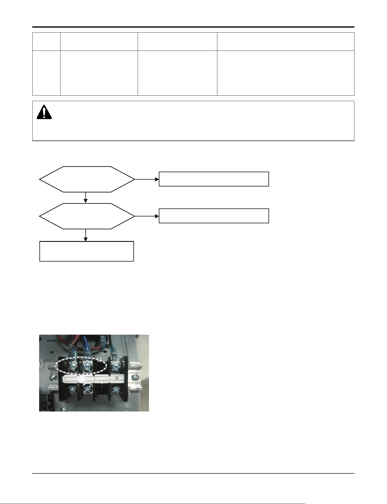
Part 5. Trouble Shooting
- 76 -
Copyright ©2017 LG Electronics. Inc. All right reserved.
Only for training and service purposes
LGE Internal Use Only
Check Point
1. Check the Input Voltage (L1~L2 ‘ 230V±10%)
2. Check Input Voltage Sensor output voltage (2.5Vdc±10%)
Is Inverter PCB Normal?
No
Replace inverter PCB assembly
Is input voltage normal ?
No
Check L1~L2 Voltage is 230V±15%
Yes
Recheck power and
installation condition
Yes
< Input Power Source Check Point >
L1
L2
n Error Diagnosis and Countermeasure Flow Chart
40
C/T
Sensor Error
• Initial current error
•
Malfunction of current detection circuit.
(Open / Short)
•
Check CT Sensor output voltage :
2.5Vdc ±5%
Display
code
Title Cause of error Check point & Normal condition
WARNING
Before checking PCB or each outdoor electric parts, wait for 3 minutes after the power is off. When measuring at standby state
of power supply, after checking the measurement mode of the meter, be careful of the short-circuits with other parts.
n Error Diagnosis and Countermeasure Flow Chart
Part 5. Trouble Shooting
- 77 -
Copyright ©2017 LG Electronics. Inc. All right reserved.
Only for training and service purposes
LGE Internal Use Only
< Inverter PCB>
< CT Sensing Check Point >
36,42kBtu/h class
Vdc
18,24,30kBtu/h class
<CT Sensing Check Point>
Vdc
2.5V
GND
Red
Black
INV_Cur
INV_Curr
ent
ent
INV_Current
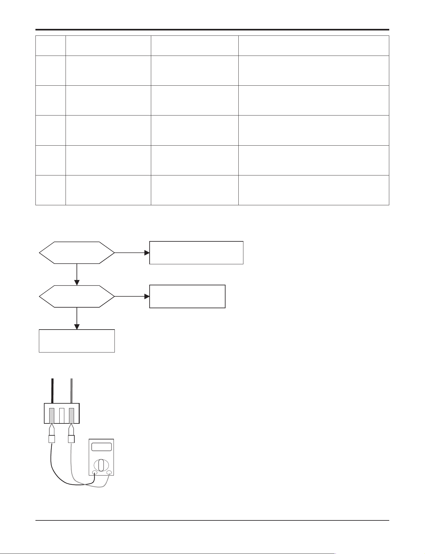
Part 5. Trouble Shooting
- 78 -
Copyright ©2017 LG Electronics. Inc. All right reserved.
Only for training and service purposes
LGE Internal Use Only
Display
code
Title Cause of error Check point & Normal condition
41 D-pipe sensor (Inverter)
• Open / Short
• Soldered poorly
• Internal circuit error
1. Bad connection of thermistor connector
2. Defect of thermistor connector (Open/Short)
3. Defect of outdoor PCB
44 Air sensor
• Open / Short
• Soldered poorly
• Internal circuit error
1. Bad connection of thermistor connector
2. Defect of thermistor connector (Open/Short)
3. Defect of outdoor PCB
45
Condenser Mid-pipesen-
sor
• Open / Short
• Soldered poorly
• Internal circuit error
1. Bad connection of thermistor connector
2. Defect of thermistor connector (Open/Short)
3. Defect of outdoor PCB
46 Suction Pipe sensor
• Open / Short
• Soldered poorly
• Internal circuit error
1. Bad connection of thermistor connector
2. Defect of thermistor connector (Open/Short)
3. Defect of outdoor PCB
48
Condenser Out-pipe sen-
sor
• Open / Short
• Soldered poorly
• Internal circuit error
1. Bad connection of thermistor connector
2. Defect of thermistor connector (Open/Short)
3. Defect of outdoor PCB
Ω
Check Point
1. Estimate the resistance of each sensor.(Unplugged)
2. Check the value of the resistor of thermistor.
D-pipe sensor (Inverter) : Normal Value of the resistor is 200kΩ at 25℃
Air sensor : Normal Value of the resistor is 10kΩ at 25℃
Cond. Mid-pipe sensor : Normal Value of the resistor is 5kΩ at 25℃
Suction pipe sensor : Normal Value of the resistor is 5kΩ at 25℃
Condenser Out-pipe sensor : Normal Value of the resistor is 5kΩ at 25℃
Is sensor connected
to PCB correctly??
Is sensor value correct?*
Connect sensor to PCB correctly
Replace sensor
Replace corresponding
outdoor unit PCB
Yes
No
No
Yes
n Error Diagnosis and Countermeasure Flow Chart
Part 5. Trouble Shooting
- 79 -
Copyright ©2017 LG Electronics. Inc. All right reserved.
Only for training and service purposes
LGE Internal Use Only
Display
code
Title Cause of error Check point & Normal condition
43
Sensor error of high
pressure
Abnormal value of sensor
(Open/Short)
• Bad connection of connector PCB
• Bad connection high pressure connector
• Defect of high pressure connector (Open/Short)
• Defect of connector PCB (Open/Short)
• Defect of outdoor main PCB.
Is sensor connected
to PCB correctly?
Connect sensor to PCB correctly
Replace corresponding
pressure sensor
Yes
No
Replace the pressure sensor
Yes
No
No
Yes
END
After replacement of outdoor
unit main PCB is the system
also abnormal?
Is pressure sensor OK?
(Check the value of
pressure sensor.
Cf. Output voltage is about
1.4V at 1500kPa)
Part 5. Trouble Shooting
- 80 -
Copyright ©2017 LG Electronics. Inc. All right reserved.
Only for training and service purposes
LGE Internal Use Only
Check Point
1. Check the indoor unit capacity.
2. Check the combination table.
Display
code
Title Cause of error Check point & Normal condition
51 Over capacity
• Over capacity Combination
• Check the indoor unit capacity.
• Check the combination table.
Model Gross max.capacity Max.single indoor unit capacity
A2UW18GFH0 24k 15k
A3UW24GFH0 33k 24k
A4UW30GFH0 40k 24k
A5UW36GFH0 48k 24k
A6UW42GFH0 56k 36k
Part 5. Trouble Shooting
- 81 -
Copyright ©2017 LG Electronics. Inc. All right reserved.
Only for training and service purposes
LGE Internal Use Only
53
Title
Communication
(Indoor ’ Outdoor)
• Communication poorly
• Power input AC 230V. (Outdoor, Indoor)
• The connector for transmission is disconnected.
• The connecting wires are misconnected.
• The communication line is shorted at GND.
• Transmission circuit of outdoor PCB is abnormal.
• Transmission circuit of indoor PCB is abnormal.
Display
code
Title Cause of error Check point & Normal condition
WARNING
Before checking PCB or each outdoor electric parts, wait for 3 minutes after the power is off. When measuring at standby state
of power supply, after checking the measurement mode of the meter, be careful of the short-circuits with other parts.
Check Point
1. Check the input power AC230V. (Outdoor, Indoor unit)
2. Check the communication wires are correctly connected.
Adjust the connection of wire Confirm the wire of "Live", "Neutral"
3. Check the resistance between communication line and GND. (Normal :
Over 2MΩ)
4. Check the connector for communication is correctly connected.
5. If one indoor unit is operated normally, outdoor PCB is no problem.
Check the another indoor unit.
* CH05 is displayed at indoor unit, CH53 is displayed at
outdoor unit.
6. If all indoor unit is displayed CH05 but outdoor PCB not
display
CH53 : Check the CN_COM and CN_POWER is correctly connected.
• 18,24,30kBtu/h class
1. In Case of CH53, Check the Connection
’ L1,L2 at the terminal block
• 36,42kBtu/h class
1. In Case of CH05, Check the Connection ’ CN_POWER,
CN_COMM at the Main PCB
2.
In Case of CH53, Check the Connection ’ CN_COMM at the
Main PCB ’ L1, L2 at the terminal block
< TERMINAL BLOCK >
L1
L2
< MAIN PCB >
N
CN-Power
CN-COMM
L1
L2
L1
L2
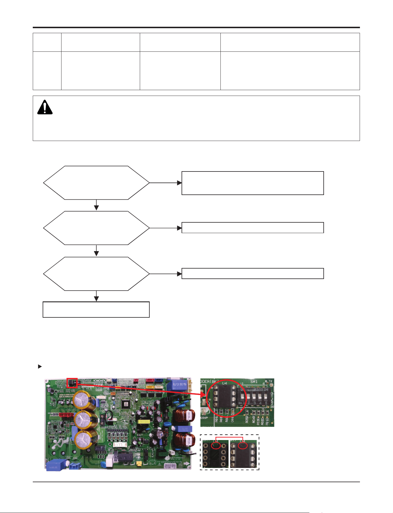
Part 5. Trouble Shooting
- 82 -
Copyright ©2017 LG Electronics. Inc. All right reserved.
Only for training and service purposes
LGE Internal Use Only
60
Inverter PCB & Main
EEPROM check sum error
EEPROM Access error
and Check SUM error
1. EEPROM contact defect/wrong insertion
2. Different EEPROM Version
3. ODU Inverter & Main PCB assembly damage
Display
code
Title Cause of error Check point & Normal condition
n Error Diagnosis and Countermeasure Flow Chart
Is EEPROM insertion normal?
No
Yes
Recheck power and installation condition
1.Check EEPROM insert direction/connection condition
2.Check EEPROM Check SUM
→ Replace if abnormality found
Is inverter PCB assembly normal?
No
Yes
Replace inverter PCB assembly
Yes
MAIN PCB assembly normal?
No
Replace MAIN PCB assembly
Check Point
- Check the EEPROM Check sum & Direction
18,24,30kBtu/h class
EEPROM
WARNING
Before checking PCB or each outdoor electric parts, wait for 3 minutes after the power is off. When measuring at standby state
of power supply, after checking the measurement mode of the meter, be careful of the short-circuits with other parts.
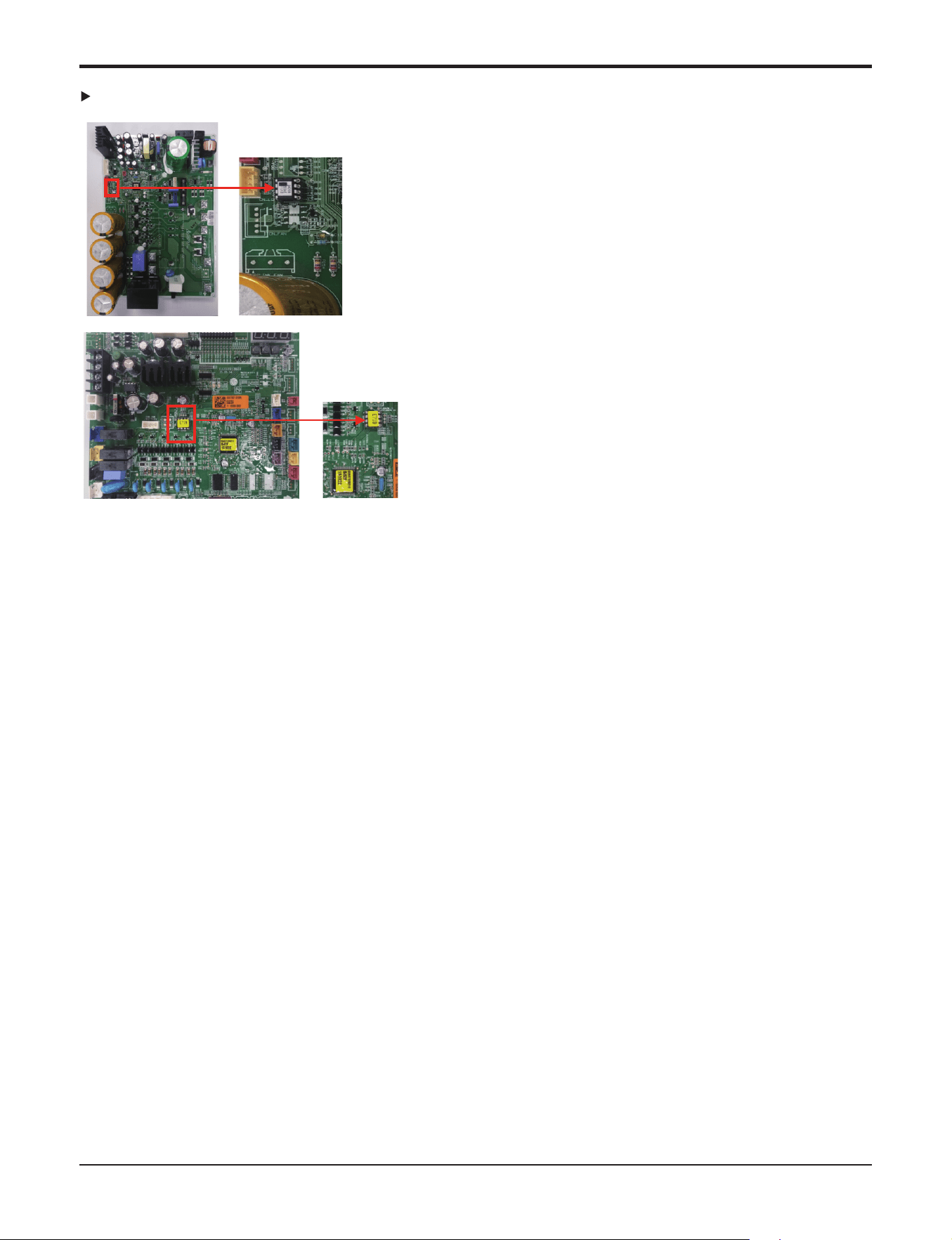
Part 5. Trouble Shooting
- 83 -
Copyright ©2017 LG Electronics. Inc. All right reserved.
Only for training and service purposes
LGE Internal Use Only
36,42kBtu/h class
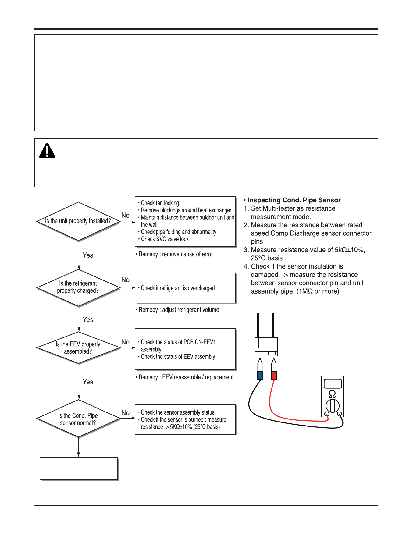
Part 5. Trouble Shooting
- 84 -
Copyright ©2017 LG Electronics. Inc. All right reserved.
Only for training and service purposes
LGE Internal Use Only
Display
code
Title Cause of error Check point & Normal condition
61
High temperature in out-
door Cond. Pipe
• Overload operation (Out-
door fan constraint,
screened, blocked)
• Outdoor unit heat ex-
changer contaminated
• EEV connector displaced
/ poor EEV assembly
• Poor Cond. Pipe sensor
assembly / burned
• Check outdoor fan constraint / screened / flow
structure
• Check if refrigerant overcharged
• Check the status of EEV assembly
• Check the status of sensor assembly / burn
CN- C/PIPE
(Violet 3Pin Connector)
Replace the Thermistor
Yes
WARNING
Before checking PCB or each outdoor electric parts, wait for 3 minutes after the power is off. When measuring at standby state
of power supply, after checking the measurement mode of the meter, be careful of the short-circuits with other parts.
Part 5. Trouble Shooting
- 85 -
Copyright ©2017 LG Electronics. Inc. All right reserved.
Only for training and service purposes
LGE Internal Use Only
62
Heatsink High error
Inverter PCB heatsink
temperature is over 85°C
1. ODU fan locking
2. Heatsink assembly of INV PCB assemble condi-
tion abnormal
3. Defect of temperature sensing circuit part defect
of INV PCB
Display
code
Title Cause of error Check point & Normal condition
n Error Diagnosis and Countermeasure Flow Chart
Is Installation
Condition Normal?
No
1. Check Pipe Clogging/ Distortion
2. Check Covering (Outdoor/Indoor Unit)
3. Check EEV Connector Assemble Condition/Normal Operation
4. Check Refrigerant Pressure
5. Check Power Wire/ Connection Condition
Reassemble or Manage if abnormality Found
1. Check Inv. PCB Screw Connection Condition
Reassemble or Manage if abnormality Found
No
Inv. PCB IGBTM Connection
Condition Normal?
Yes
1. Check Outdoor Unit Fan Motor Operation or Lock
Reassemble or Manage if abnormality Found
No
Is ODU Fan Motor Normal?
Yes
1. Reset
Replace Inv. PCB Assembly
No
Is Inv. PCB assembly
Normal?
Yes
Recheck Power and
Installation Condition
Yes
Check Point
1. Check resistance between No.19 pin and NO.20 pin of PCB PFC module
2. Resistance value should be in 7kΩ ±10%.(at 25°C).
3. Check Inv. PCB Screw Connection Condition – only 36,42kBtu/h class
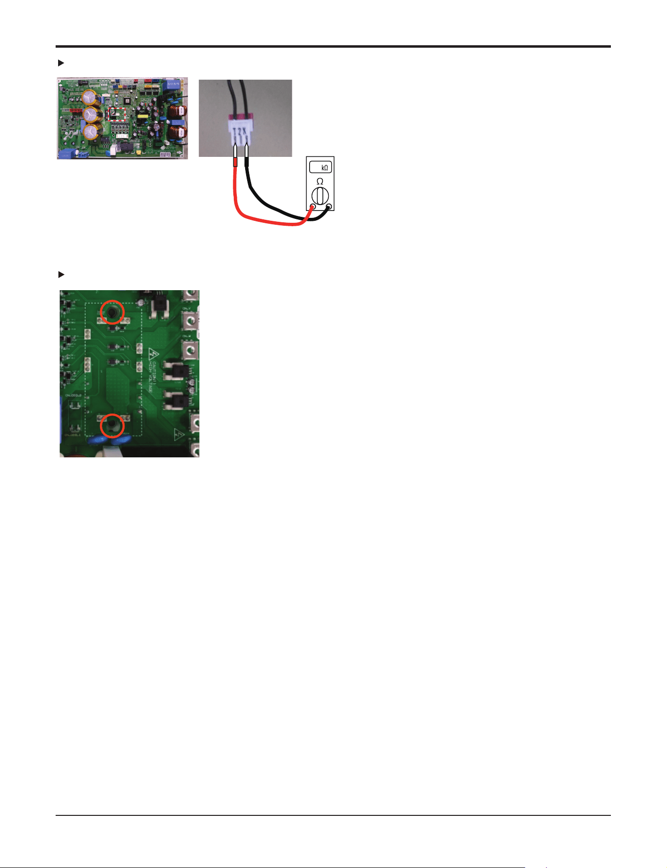
Part 5. Trouble Shooting
- 86 -
Copyright ©2017 LG Electronics. Inc. All right reserved.
Only for training and service purposes
LGE Internal Use Only
Check Screw Connection Condition
36,42kBtu/h class
18,24,30kBtu/h class
PFCM :
Measuring resistance
between No.19,20 pin
Red
Black
10
9~11KΩ
Part 5. Trouble Shooting
- 87 -
Copyright ©2017 LG Electronics. Inc. All right reserved.
Only for training and service purposes
LGE Internal Use Only
65
Heatsink Sensor error
Inverter PCB heatsink
sensor is open or short
1. ODU fan locking
2. Heatsink assembly of INV PCB assemble
condition abnormal
3. Defect of temperature sensing circuit part defect
of INV PCB
Display
code
Title Cause of error Check point & Normal condition
Is installation
condition normal ?
No
Yes
1. Check fan locking
2. Check covering of heat exchanger
3. Check distance between ODU and obstacles
4. Check pipe distortion and abnormality
5. Check service valve is opened
→ Eliminate causes for abnormal condition
Check resistance between NO.19 pin and NO.20 pin
of PFC module
Check resistance between NO.24 pin and NO.25 pin
of PFC module
→ 7KΩ 10%(at 25°C)
→ Replace PCB if abnormality found
Is assemble condition
of INV PCB heatsink normal ?
Is PCB temperature
sensing part normal ?
No
No
Yes
Check assemble condition between INV PCB heatsink and
IGBTM Module
→ Reassemble if abnormality found
Recheck installation condition
and connection of Heat sink
Yes
n Error Diagnosis and Countermeasure Flow Chart
Check Point
1. Check resistance between No.19 pin and NO.20 pin of PCB PFC module
2. Resistance value should be in 7kΩ ±10%.(at 25°C).
3. Check the PFC Module No.19, 20.
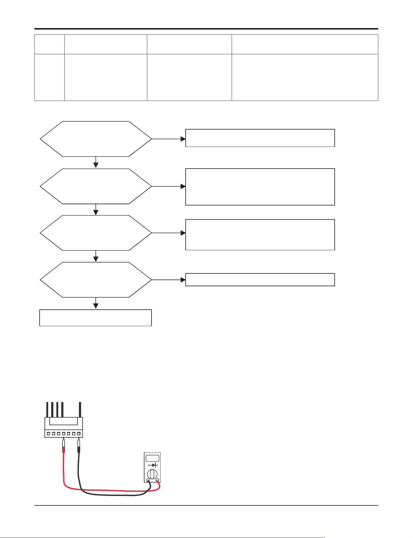
Part 5. Trouble Shooting
- 88 -
Copyright ©2017 LG Electronics. Inc. All right reserved.
Only for training and service purposes
LGE Internal Use Only
67
Fan Lock Error
Fan RPM is 10RPM or
less for 5 sec. when ODU
fan starts or 40 RPM or
less after fan starting.
1. ODU fan locking
2. Heatsink assembly of INV PCB assemble condi-
tion abnormal
3. Defect of temperature sensing circuit part defect
of INV PCB
Display
code
Title Cause of error Check point & Normal condition
Is ODU Fan Motor Assemble
condition normal?
No
Yes
Recheck power and installation condition
Check ODU Fan Motor assemble condition and fan locking
→ Reassemble or replace if abnormality found
Is ODU Fan Motor normal?
No
Yes
1. Set the multi tester to diode mode.
2. Check voltage between 1pin and 4pin of Fan Motor
(1Ţ0.2V)
3. Replace Inverter PCB if abnormality found.
Is wire connection of
ODU Fan Motor wire normal?
No
Yes
Check wiring between OUD fan motor and Inverter PCB
( Check if Hall Senor and Motor output terminal color is
matched)
→Reassemble if abnormality found
Is Inverter PCB assembly normal?
No
Yes
Replace Inverter PCB assembly
n Error Diagnosis and Countermeasure Flow Chart
Check Point
1. Check voltage between 1pin and 4pin of Fan Mortor connector (Tester diode mode)
2. Voltage value should be in 1V ±0.2V.
3. Do not replacing all of fan motor and PCB at once.
Check error code again, after replacing the abnormal part (Fan Motor or PCB) first.
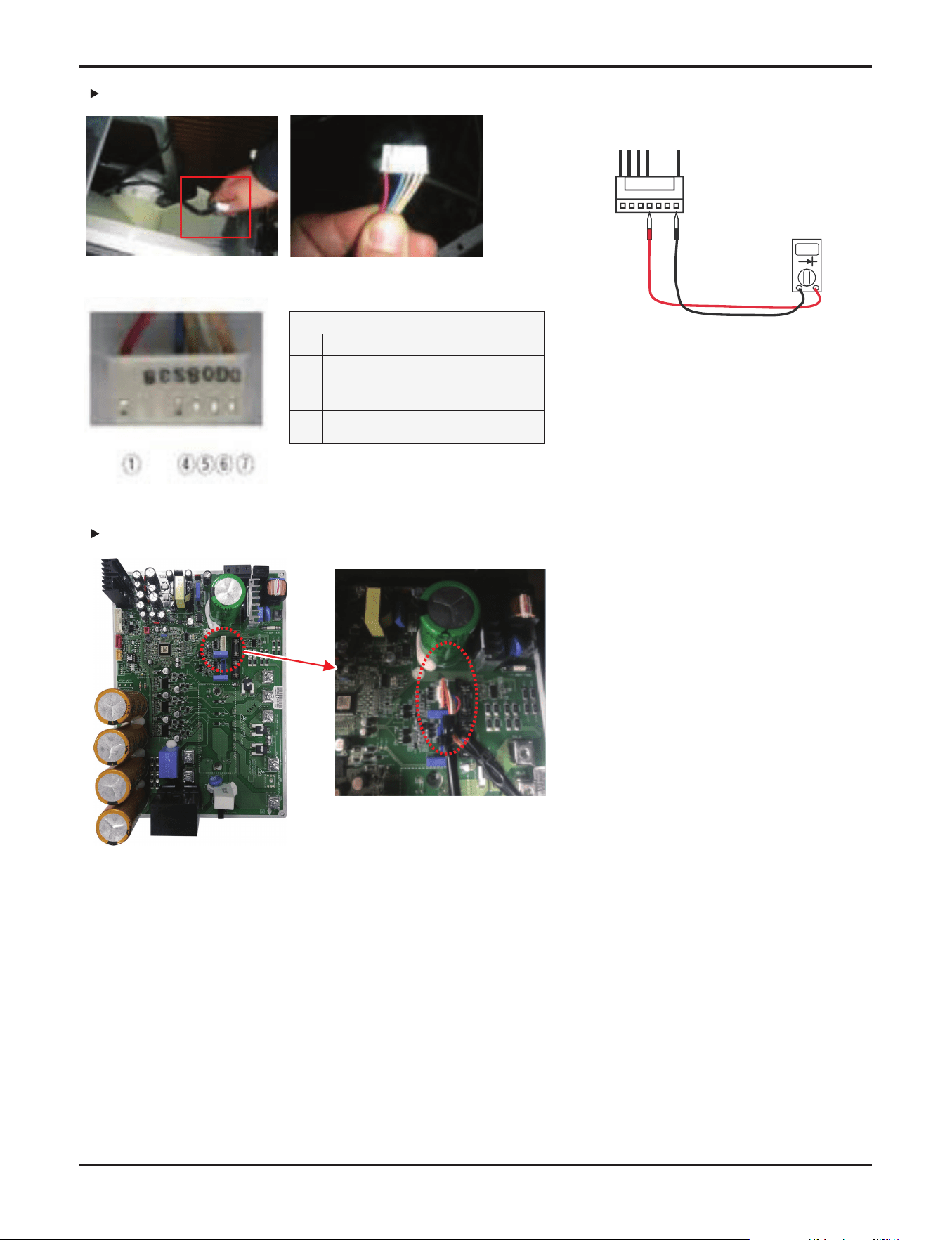
Part 5. Trouble Shooting
- 89 -
Copyright ©2017 LG Electronics. Inc. All right reserved.
Only for training and service purposes
LGE Internal Use Only
<Inverter PCB>
36,42kBtu/h class
18,24,30kBtu/h class
Tester
Fan motor
connector
Check voltage betwen
1pin and 4pin of fan motor
-. Checking wire
terminals for
possible short
Te s t e r ܄ԟۼHᴦQPEI@
ڸڻ
ᴬᴬ
ڼڻ
d@Ẹ
@Ẹ
d@Ẹ
@Ẹ
d@Ẹ
@Ẹ
d@Ẹ
@Ẹ
ڽڻ
ᴬᴬ
ھڻ
ڸڻڼڽھ
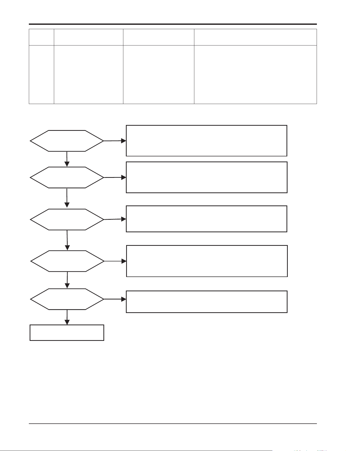
Part 5. Trouble Shooting
- 90 -
Copyright ©2017 LG Electronics. Inc. All right reserved.
Only for training and service purposes
LGE Internal Use Only
73
AC input instant over cur-
rent error
(Matter of software)
Inverter PCB input power
current is over 48A(peak)
for 2ms
1. Overload operation (Pipe clogging/Covering/EEV
defect/Ref.overcharge)
2. Compressor damage
(Insulation damage/Motor damage)
3. Input voltage abnormal (L, N)
4. Power line assemble condition abnormal
5. Inverter PCB assembly damage
(input current sensing part)
Display
code
Title Cause of error Check point & Normal condition
n Error Diagnosis and Countermeasure Flow Chart
No
1.Check Pipe clogging/distortion
2.Check Covering (Indoor/Outdoor Unit)
3.Check EEV connector assemble condition/normal operation
4.Check refrigerant pressure
→ Reassemble or manage if abnormality found
Is installation
condition normal?
Is compressor
Wire connection
condition normal?
1.Check inverter PCB assembly U,V,W connector connection condition
2.Check wire disconnection and wiring
3.Check compressor terminal connection condition(bad contact)
→ Reassemble if abnormality found
Is AC input Wire connection
condition normal?
1.Check L1,L2 connection condition
2.Check wire disconnection and wiring
→ Reassemble if abnormality found
Is inverter PCB assembly
normal?
Yes
No
Recheck power and
installation condition
Yes
Yes
Yes
No
No
Yes
No
Check
L1~L2 phase voltage is 230V ± 15%
→ Check connection condition and wiring if power is abnormal
Is input voltage normal?
Check inverter PCB assembly IPM normality
→ Replace inverter PCB assembly
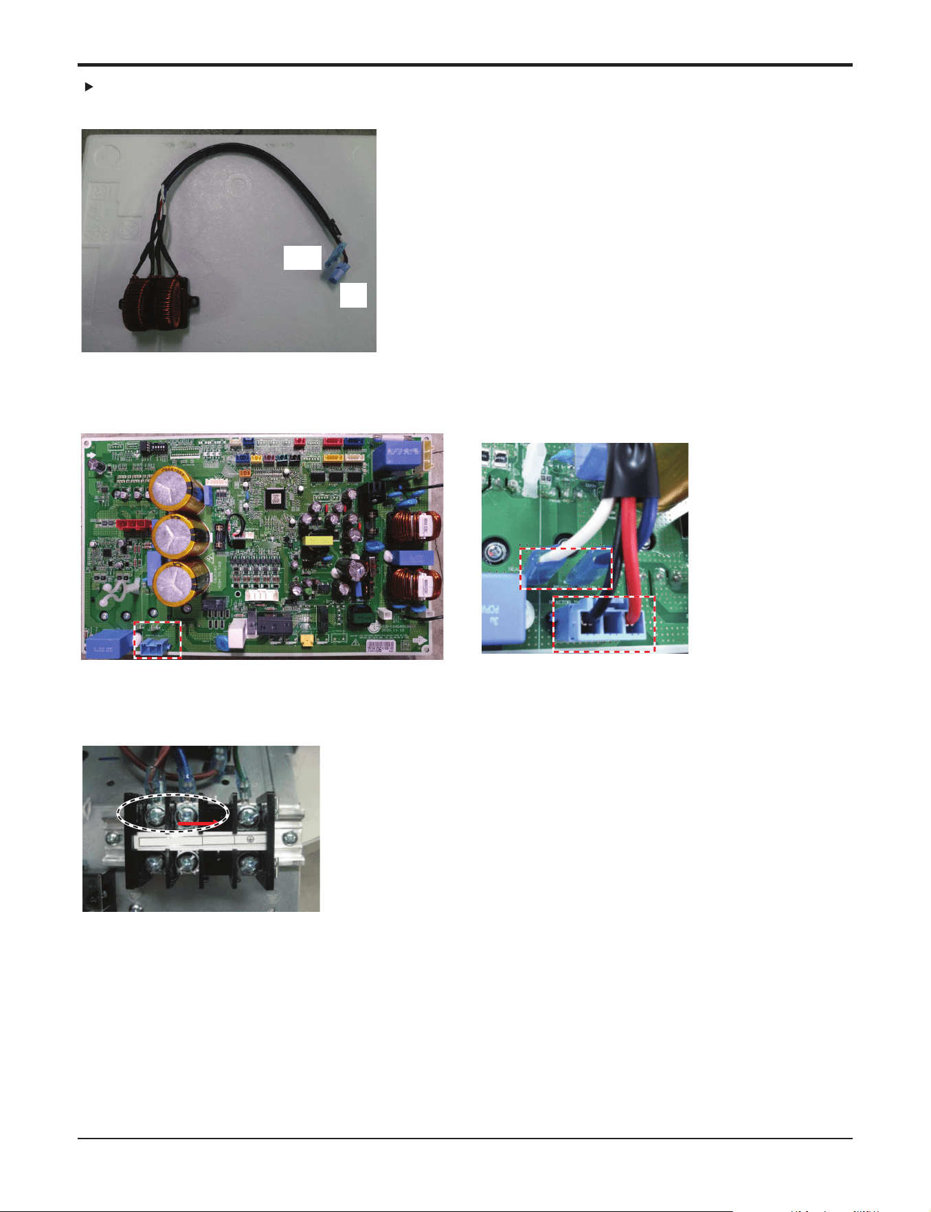
Part 5. Trouble Shooting
- 91 -
Copyright ©2017 LG Electronics. Inc. All right reserved.
Only for training and service purposes
LGE Internal Use Only
< Input Power Source Check Point >
< Main PCB wiring Check Point >
< Noise Filter wiring Check Point >
OUT
IN
18,24,30kBtu/h class
IN
OUT
OUT
L1
L2
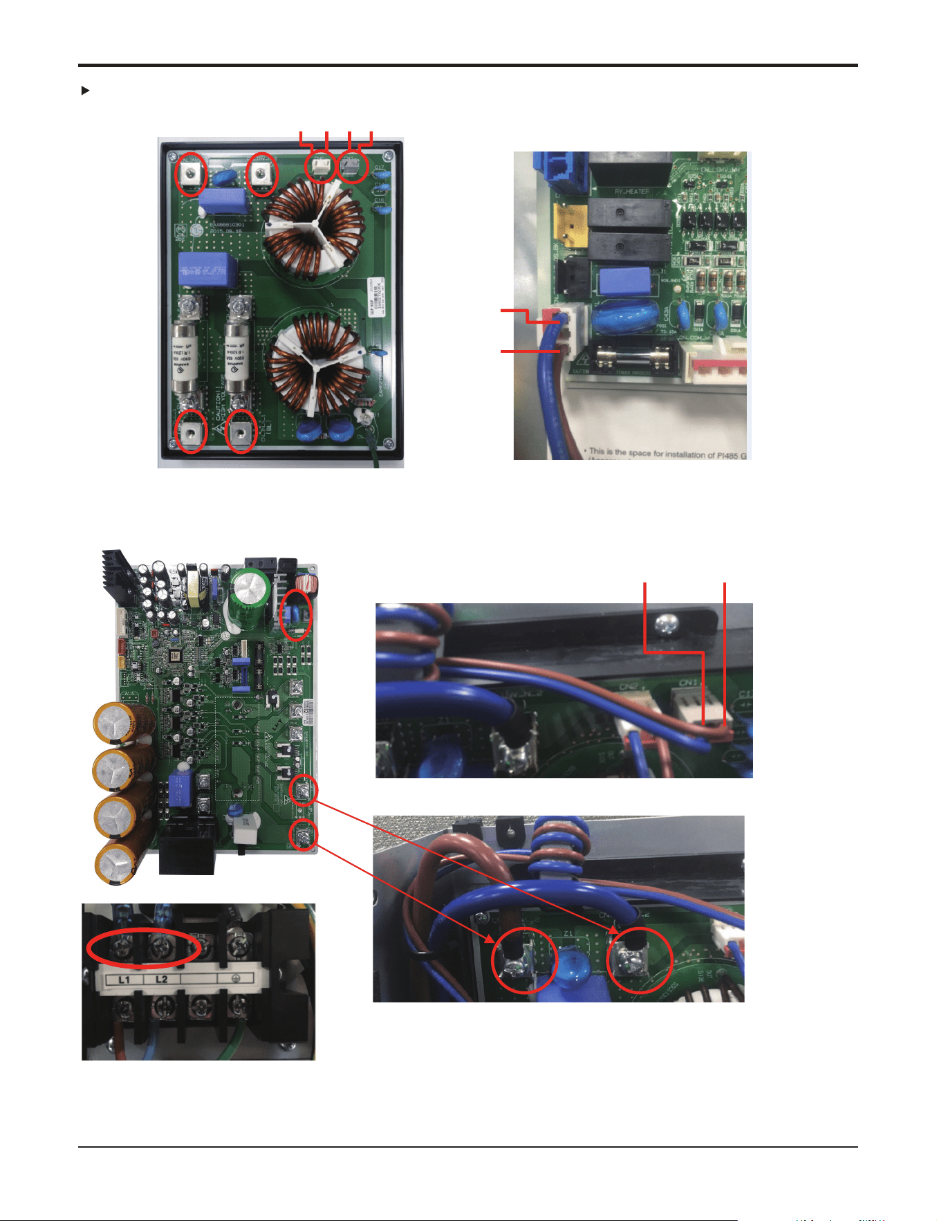
Part 5. Trouble Shooting
- 92 -
Copyright ©2017 LG Electronics. Inc. All right reserved.
Only for training and service purposes
LGE Internal Use Only
< Noise Filter wiring Check Point >
< Main PCB wiring Check Point >
< Input Power Source Check Point >
< Inverter PCB wiring Check Point >
L2
L2
L1
L2
L2 L1
L1
L1
36,42kBtu/h class
L1 L2L2 L1 L2 L1
L1 L2
L1
L2