Loading ...
Regulatory Information
FCC Informa�on
Please take a�en�on that changes or modica�on not expressly approved by the party
responsible for compliance could void the user’s authority to operate the equipment.
FCC compliance: This equipment has been tested and found to comply with the limits for a
Class B digital device, pursuant to part 15 of the FCC Rules. These limits are designed to
provide reasonable protec�on against harmful interference in a residen�al installa�on. This
equipment generates, uses and can radiate radio frequency energy and, if not installed and
used in accordance with the instruc�ons, may cause harmful interference to radio
communica�ons. However, there is no guarantee that interference will not occur in a
par�cular installa�on. If this equipment does cause harmful interference to radio or
television recep�on, which can be determined by turning the equipment o and on, the user
is encouraged to try to correct the interference by one or more of the following measures:
—Reorient or relocate the receiving antenna.
—Increase the separa�on between the equipment and receiver.
—Connect the equipment into an outlet on a circuit dierent from that to which the receiver
is connected.
—Consult the dealer or an experienced radio/TV technician for help.
This equipment should be installed and operated with a minimum distance 20cm between
the radiator and your body.
FCC Condi�ons
This device complies with part 15 of the FCC Rules. Opera�on is subject to the following two
condi�ons:
1. This device may not cause harmful interference.
2. This device must accept any interference received, including interference that may cause
undesired opera�on.
2006/66/EC (ba�ery direc�ve): This product contains a ba�ery that cannot
be disposed of as unsorted municipal waste in the European Union. See
the product documenta�on for specic ba�ery informa�on. The ba�ery is
marked with this symbol, which may include le�ering to indicate cadmium
(Cd), lead (Pb), or mercury (Hg). For proper recycling, return the ba�ery to
your supplier or to a designated collec�on point. For more informa�on see:
www.recyclethis.info
2012/19/EU (WEEE direc�ve): Products marked with this symbol cannot be
disposed of as unsorted municipal waste in the European Union. For
proper recycling, return this product to your local supplier upon the
purchase of equivalent new equipment, or dispose of it at designated
collec�on points. For more informa�on see: www.recyclethis.info
This product and - if applicable - the supplied accessories too are marked
with "CE" and comply therefore with the applicable harmonized European
standards listed under the RE Direc�ve 2014/53/EU, the EMC Direc�ve
2014/30/EU, the RoHS Direc�ve 2011/65/EU.
Warning
In the use of the product, you must be in strict compliance with the electrical safety
regula�ons
of the na�on and region.
CAUTION: To reduce the risk of re, replace only with the same type and ra�ng of fuse.
CAUTION: This equipment is for use only with Hikvision’s bracket. Use with other (carts,
stands, or carriers) may result in instability causing injury.
To prevent possible hearing damage, do not listen at high volume levels for long periods.
Please use the power adapter, which is provided by normal company. The power
consump�on cannot be less than the required value.
Do not connect several devices to one power adapter as adapter overload may cause over-
heat or re hazard.
Please make sure that the power has been disconnected before you wire, install or
dismantle the device.
When the product is installed on wall or ceiling, the device shall be rmly xed.
If smoke, odors or noise rise from the device, turn o the power at once and unplug the
power cable, and then please contact the service center.
If the product does not work properly, please contact your dealer or the nearest service
center. Never a�empt to disassemble the device yourself. (We shall not assume any
responsibility for problems caused by unauthorized repair or maintenance.)
Cau�on
+ iden�es the posi�ve terminal(s) of equipment which is used with, or generates
direct current. + iden�es the nega�ve terminal(s) of equipment which is used with,
or generates direct current.
No naked ame sources, such as lighted candles, should be placed on the equipment.
The USB port of the equipment is used for connec�ng to a USB ash drive only.
The serial port of the equipment is used for debugging only.
Burned ngers when handling the ngerprint sensor metal. Wait one-half hour a�er
switching o before handling the parts.
Install the equipment according to the instruc�ons in this manual.
To prevent injury, this equipment must be securely a�ached to the oor/wall in
accordance with the installa�on instruc�ons.
Do not drop the device or subject it to physical shock, and do not expose it to high
electromagne�sm radia�on. Avoid the equipment installa�on on vibra�ons surface or
places subject to shock (ignorance can cause equipment damage).
Do not place the device in extremely hot (refer to the specica�on of the device for
the detailed opera�ng temperature), cold, dusty or damp loca�ons, and do not expose
it to high electromagne�c radia�on.
The device cover for indoor use shall be kept from rain and moisture.
Exposing the equipment to direct sun light, low ven�la�on or heat source such as
heater or radiator is forbidden (ignorance can cause re danger).
Do not aim the device at the sun or extra bright places. A blooming or smear may
occur otherwise (which is not a malfunc�on however), and aec�ng the endurance of
sensor at the same �me.
Please use the provided glove when open up the device cover, avoid direct contact
with the device cover, because the acidic sweat of the ngers may erode the surface
coa�ng of the device cover.
Please use a so� and dry cloth when clean inside and outside surfaces of the device
cover, do not use alkaline detergents.
Please keep all wrappers a�er unpack them for future use. In case of any failure
occurred, you need to return the device to the factory with the original wrapper.
Transporta�on without the original wrapper may result in damage on the device and
lead to addi�onal costs.
Improper use or replacement of the ba�ery may result in hazard of explosion. Replace
with the
same or equivalent type only. Dispose of used ba�eries according to the instruc�ons
provided by the ba�ery manufacturer.
Biometric recogni�on products are not 100% applicable to an�-spoong
environments. If you require a higher security level, use mul�ple authen�ca�on
modes.
Please make sure that the biometric recogni�on accuracy will be aected by the
collected pictures' quality and the light in the environment, which cannot be 100%
correct.
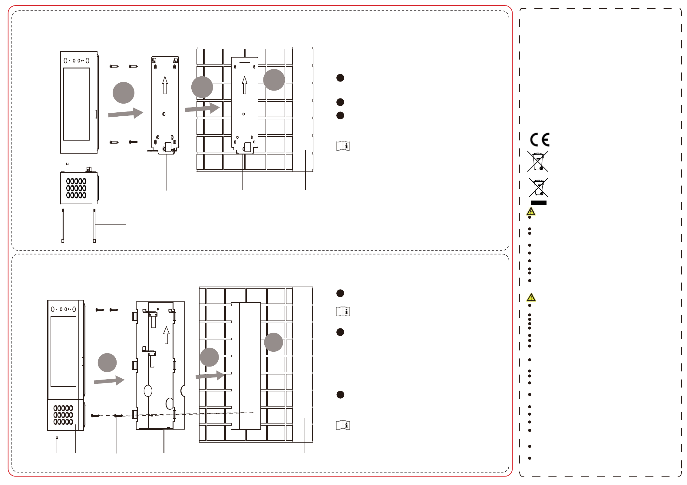
Flush Mounting
Surface Mounting
1
2
3
Set
Screw
Splice
Set
Screw
Screws Mounting Plate Mounting Template Wall
Set Screw
Door Station
Screws
Gang Box
Wall
1
2
3
1
2
3
Paste the mounting template on the wall according to
the installation requirements. Drill holes acording to
the template. Insert the expansion bolts into the screw
holes.
Fix the mounting plate to the wall with 4 supplied
screws.
Wire the device and cover the rear panel with 2
screws. Fix the device to the mounting plate and fix
the device with the set screws. Fix the sub module to
the door station with 2 set screws.
Do not touch the TF card slot and other devices during the
process of plugging in and unplugging the power
interface.
Apply Silicone sealant among the joints between the
device and the wall (except the lower side) to keep the
raindrop from entering.
Do not touch the TF card slot and other devices during the
process of plugging in and unplugging the power
interface.
Apply Silicone sealant among the joints between the
device and the wall (except the lower side) to keep the
raindrop from entering.
Cave an installation hole on the wall. Pull the cable out
from the wall.
Install the gang box into the wall.
a. Insert the gang box into the installation hole.
Mark the gang box screw holes’ position with a
marker, and take out the gang box.
b. Drill 4 screw holes according to the marks on the
wall, and insert the expansion sleeves into the
screw holes.
c. Fix the gang box with 4 screws.
d. Remove the mounting ears of the gang box.
Fix the sub module to the door station with 2 set
screws. Wire the device and cover the rear panel
with 2 screws. Insert the door station into the gang
box and x it with set screw.
The suggested dimension of the installation hole is 313.5
mm (H) × 128.9 mm (W) × 41.3 mm (D).
The suggested length of the cables left outside is 250 mm.
1
2
3