Thank you for purchasing a Sealey product. Manufactured to a high standard this product will, if used according to these instructions and properly maintained,
give you years of trouble free performance.
1. SAFETY
2. INTRODUCTION
3. SPECIFICATION
WARNING! Turn off, or disconnect from, air supply before servicing or performing any maintenance and when unit is not in use.
Failure to comply with this instruction may damage the unit and will invalidate your warranty.
WARNING! Wear approved ear, eye, hand and respiratory protection when operating the blaster. A full range of personal safety equipment
is available from your Sealey dealer.
Maintain correct balance and ensure firm footing.
Spillages of abrasive material, which may be slippery, must be cleaned up immediately to avoid injury.
Locate blaster in a suitable, well ventilated, work area. Keep area clean and tidy and free from unrelated materials, and ensure that
there is adequate lighting.
Maintain the blaster in good condition (use an authorised service agent).
Replace or repair damaged parts. Use recommended parts only. Non-authorised parts may be dangerous and will invalidate the warranty.
Keep the unit clean for best and safest performance.
Remove ill fitting clothing. Remove ties, watches, rings, other loose jewellery and contain long hair.
Always keep the blast nozzle directed at the workpiece.
If a failure or malfunction occurs disconnect from air supply immediately.
Keep all other persons away from the working area. Contact with high pressure blast or inhaling the dust generated is dangerous.
DO NOT use the blaster for any purpose other than that for which it is designed.
DO NOT operate the blaster if any parts are missing or damaged as this may cause failure and/or personal injury.
DO NOT use any abrasive which contains free silica. We recommend Sealey Shot Blasting Grit, item B/25KG.
DO NOT attempt to clear a blocked nozzle while the unit is pressurised.
DO NOT allow untrained persons to operate the blaster.
DO NOT get the blaster wet or use in damp or wet locations or areas where there is condensation.
DO NOT leave the blaster operating unattended.
DO NOT operate the blaster when you are tired, under the influence of alcohol, drugs or intoxicating medication.
DO NOT stand or sit on the blaster.
DO NOT direct air from the air hose at yourself or others.
DO NOT operate system with air supply exceeding 125psi.
INSTRUCTIONS FOR:
SHOT BLASTERS WITH WATER TRAP AND
WHEELS 37/75ltr
MODEL No's: SB997 & SB998
4. AIR SUPPLY
WARNING! Ensure the air supply does not exceed 125psi while
operating the unit. Too high an air pressure will shorten the life of the unit
owing to excessive wear and may cause damage and/or personal injury.
4.1. Ensure the blaster air valve (trigger) is in the ‘Off’ position before
connecting to the air supply.
4.2. Keep the air hose between the compressor and the unit a reasonable
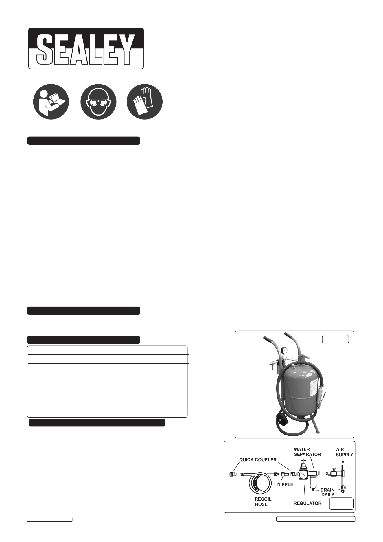
length and install an air filter and water separator (fig.1).
4.3. Drain the air tank daily. Water in the air line will damage the unit.
4.4. The recommended hook-up procedure is shown in fig.1.
4.5. The minimum hose diameter should be 1/4" I.D. and fittings must
have the same inside dimensions.
4.6. Use correct hoses and fittings.
4.7. Keep hoses away from heat, oil and sharp edges. Check hoses for wear
and ensure that all connections are secure.
Pressured tank for maximum power with 2.4mtr rubber hose, four ceramic nozzles and in-line water trap for moisture-free grit blasting.
Supplied with bayonet air line coupling and air flow regulator. Accepts a variety of grits up to 700microns and suitable for stripping rust and
paint from wheels, chassis, panels and other corroded/painted surfaces.
Model: SB997 SB998
Maximum Fill Weight: 46kg 92kg
Working Pressure: 60 ~ 125psi
Air Requirements: 6 ~ 25cfm
Air Inlet Size: 1/4” BSP
Nozzle Sizes: 2, 2.5, 3, 3.5 & 5mm
Maximum Grit Size: 700microns
Maximum Grit Consumption: 180kg/hr
fig.1
SB997
Original Language Version
Refer to
Instructions
Wear Eye
Protection
Wear Protective
Gloves
SB997, SB998 Issue: 4(SP) -09/02/15
© Jack Sealey Limited
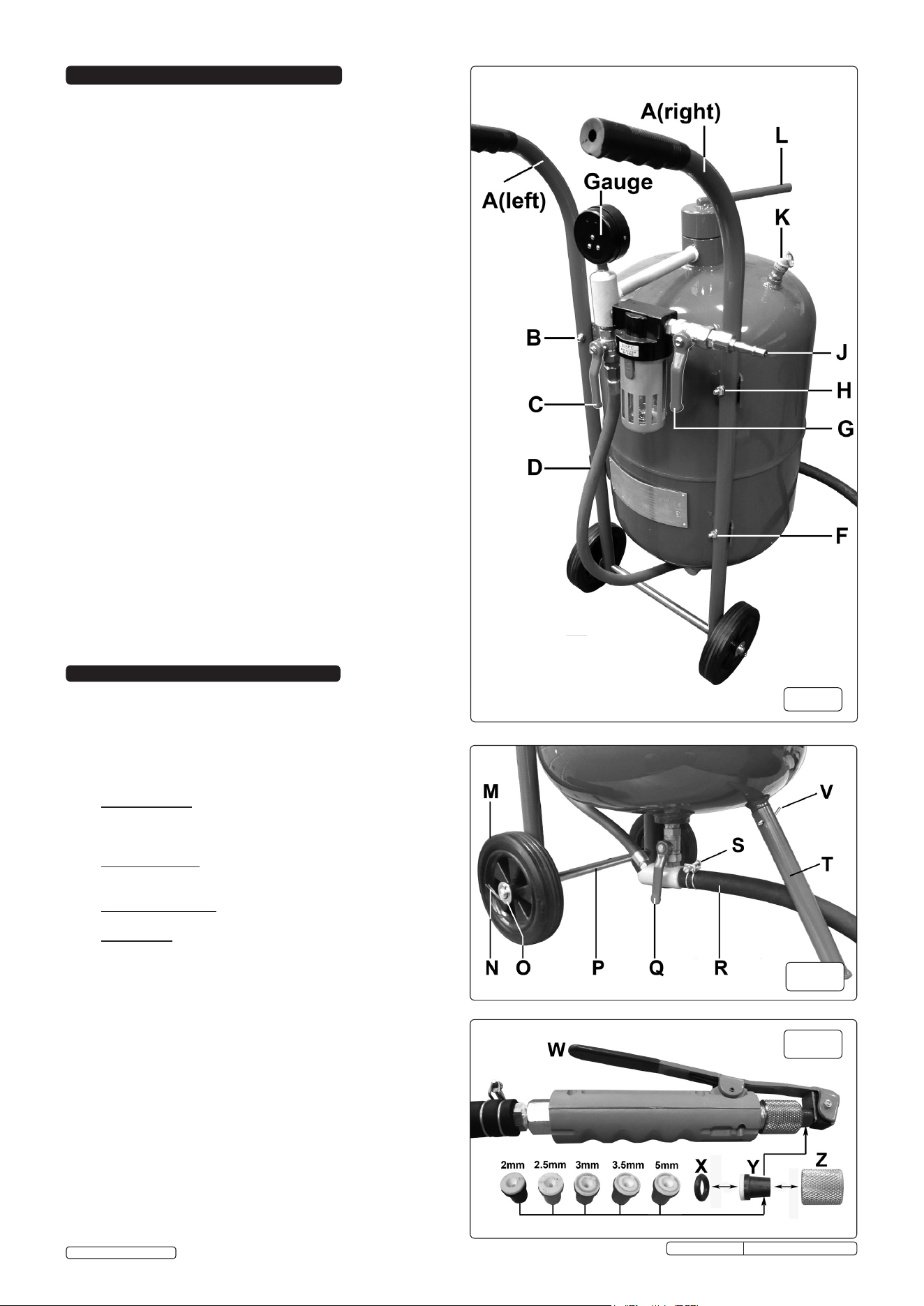
fig.5
fig.4
6. PREPARATION
WARNING! Ensure that you read, understand and apply the
safety instructions in Section 1 before use.
WARNING! Wear approved ear, eye, hand and respiratory
protection when operating the blaster.
WARNING! Ensure the air supply does not exceed 125psi
while operating the unit.
6.1 Control valves.
6.1.1. Air Supply Valve See fig.3G. This valve controls the flow of air
coming into the unit from a compressor or workshop air supply.
When this valve is opened the incoming pressure of air will
register on the gauge and the tank will start to pressurise.
6.1.2. Gun Supply Valve See fig.3C. This valve controls the flow of air
to the sand pick up point at the base of the unit and on to the
blasting gun.
6.1.3. Sand Metering Valve See fig.4Q. This valve controls the
amount of sand flowing down from the tank.
6.1.4. Blasting Gun See fig.5W. This valve opens the flow of sand
from the blasting nozzle and should be either open or shut.
6.2. Abrasives.
There are two types of abrasive grit:
6.2.1. Expendable - Use once and dispose of, recommended for
large surfaces - Copper Slag and Olivene (silica-free sand).
We recommend Sealey Blasting Grit, part number B/25KG
(Use with the 5mm nozzle).
6.2.2. Re-usable - more expensive and recommended for cabinets -
Glass Beads and Fused Alumina.
6.3. Filling the tank with abrasive.
6.3.1. Close the Sand Metering Valve See fig.4Q. Valve lever should
be at right angles to the fitting
WARNING! If an air line is connected ensure the tank is
depressurised by turning off the air supply and operating
the blasting gun until the pressure gauge registers zero.
6.3.2. Undo the tank cap using the attached lever. See fig.3L.
6.3.3 Insert a funnel into the opening.
6.3.4. Fill the tank up to 3/4 full only.
6.3.5. Refit the tank cap ensuring that the 'O' ring seal is in place and
tighten fully.
Original Language Version
fig.3
5. ASSEMBLY
WARNING! Before operating the unit ensure you read,
understand and apply Section 1 Safety Instructions.
5.1 Assembling the handles and wheels.
5.1.1. Place a protective layer on the floor such as cardboard or cloth
and lay the tank down with the water trap and gauge upwards.
Place blocks either side of the tank to prevent it rolling.
5.1.2. There is a specific left hand and a specific right hand handle
as the mounting holes in them are at different angles. When
correctly fitted the two handles should be parallel.
Referring to fig.3, loosely attach the two handles (A) onto the
fixing brackets (B, D, F & H) using the nuts, bolts and
washers provided. Do not tighten yet.
5.1.3 Referring to fig.4, slide the axle (P) through the holes at the
bottom of each handle so that it protrudes equally either side.
Slide a wheel (M) onto each end of the axle followed by a
washer (O). Fix each wheel by sliding a split pin (N) through
the holes in the end of the axle and retain the assembly by
bending over the pins.
5.1.4 Now tighten the nuts and bolts at the four handle mounting
positions. (B, D, F & H in fig.3).
5.2 Assembling the front foot.
5.2.1 Now lay the tank down on its handles and referring to fig.4, fit
the front foot (T) to the spigot welded onto the tank and retain
the assembly by putting the split pin (V) through the foot and
spigot and bending it over.
5.3 Attaching the blasting hose.
5.3.1 Referring to fig.4, take the open end of the blasting hose (R)
and slide the wire screw clamp (S) over the end of it. Now
push the hose fully onto the sand outlet fitting below the sand
metering valve and tighten the wire screw clamp to retain it.
5.4 Fixing / changing the blasting nozzle.
5.4.1 Referring to fig.5, depress and hold the blasting gun handle
(W) to release the seal on the nozzle. Unscrew and remove
the knurled nozzle holder (Z) and release the handle (W).
Push the nozzle (Y) and the 'O' ring (X) out of the holder.
Insert the required nozzle into the back of the holder (Z)
followed by the 'O' ring (X). Depress the blasting gun handle
and screw the knurled nozzle holder back into place.
SB997, SB998 Issue: 4(SP) - 09/02/15
© Jack Sealey Limited

7. OPERATION
8. MAINTENANCE
WARNING! Wear approved ear, eye, hand and respiratory protection when operating the blaster.
7.1. Close all valves before connecting the air.
7.1.1. Connect the air supply as described in Section 3 to the air inlet fitting. See fig.3J.
7.1.2. Set the incoming air pressure. Do not exceed 125psi.
7.1.3. Open the Air Supply Valve (See fig.3G) and allow the tank to pressurise.
7.1.4. Open the Sand Metering Valve. See fig.4Q. Valve lever should in line with the fitting.
7.1.5. Open the Gun Supply Valve. See fig.3C.
7.2. The unit is now ready for use.
7.2.1. Fully depress the Blasting Gun lever to commence blasting.
7.2.2. Before blasting unfamiliar material, spot test to ensure that damage/pitting will not occur to the material.
7.2.3. Use even passes of the blaster to remove material such as rust, body filler or other soft materials. Do not blast in any one
area for more than a few seconds at a time.
7.3. The unit is supplied with 5 ceramic nozzles. See fig .5. Select the appropriate nozzle for the task.
7.3.1. To change the nozzle refer to section 4.4
WARNING! DO NOT use the sand blaster without a nozzle fitted.
WARNING! Disconnect from the air supply before performing any maintenance!
WARNING! Check regularly for wear in those components that carry the air/abrasive mixture, in particular the blast hose.
8.1. Blast Hose - To inspect the blast hose and associated fittings first close the Sand Metering Valve, see fig.4Q. Wearing your protective
clothing, operate the blasting gun until only air is passing through it. Close your hand lightly around the hose and slide it along the full
length with the blasting gun closed. You should be able to feel any air leaks from the hose and associated fittings. Also, where the
internal wall of the hose has worn thin the hose will begin to blister. If any blisters or leaks from the hose are discovered the hose can
no longer be used and must be replaced immediately.
8.2. Blast Nozzles - Check for wear and replace as necessary.
8.3. Sand Outlet Fitting - The sand outlet fitting to which the blast hose is connected should also be periodically inspected for wear.
WARNING! The following items should also be checked on a regular basis.
8.4. Hoses & Clips - Replace immediately at any sign of damage.
8.5. Filler Cap Gasket - Check to ensure it provides an airtight seal.
8.6. Water Separator - Drain before use by loosening drain screw while separator is pressurised.
NOTE: It is our policy to continually improve products and as such we reserve the right to alter data, specifications and component parts without prior notice.
IMPORTANT: No liability is accepted for incorrect use of this product.
WARRANTY: Guarantee is 12 months from purchase date, proof of which will be required for any claim.
Original Language Version
SB997, SB998 Issue: 4(SP) - 09/02/15
Environmental Protection
Recycle unwanted materials instead of disposing of them as waste. All tools, accessories and packaging should be sorted, taken to a recycling
centre and disposed of in a manner which is compatible with the environment. When the product becomes completely unserviceable dispose of it
according to local regulations.
01284 757500
01284 703534
sales@sealey.co.uk
Sole UK Distributor, Sealey Group,
Kempson Way, Suffolk Business Park,
Bury St. Edmunds, Suffolk,
IP32 7AR
www.sealey.co.uk
© Jack Sealey Limited