
Cooker Hood User Manual
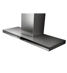
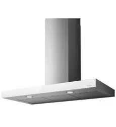
Vida X/A/90
Vida BK/A/90
400-682-9123
Zhejiang Elica Putian Electric Co., Ltd.
Add:No.88 Putian Avenue, Shengzhou,
Zhejiang Province,P.R.China(312400)
Tel: +86 0575-83366001
Fax:+86 0575-83366000
Service Hotline
Dear Elica customer:
Please pull out the power plug if the hood are not used for a long
time.
New Hood Packaging
All packaging materials are environmentally friendly and
recyclable. Please dispose them by environmentally-friendly
attitude in order to keep a favorable environment.
Old Hood Management
Please discard old hood if it cannot be used any longer.
Before discarding, please dispose into an unusable status. Old
hood includes some recyclable materials. Please help to dispose
in a proper way or recycle it.
Thanks for choosing our product.
Please read this specification carefully before using the product and
keep it for future consultation.
Any failure and losses caused by ignoring the items mentioned below
and cautions mentioned in the user manual are not covered by our
warranty and any liability.
Please keep all documents and receipt in a safety place for future
reference.
Caution:
We reserves the right to the interpretation of the contents mentioned
in this user manual. Any specification is subject to change without notice.
IMPORTANT:
9
Analysis and Solution on Common Faults
Fault
Reason
Solution
motor stop
running and
no light
hood body
shake
poor absortion
(*)Replace lamp: Professionals only.
.
1. No electricity or plug loose
2. circuit failure or switch
is broken
3. rosin welding joint on PCB
or O/C
1. control switch failure
2. motor burn out
3. capacitor is broken
1. control switch failure
2. lamp is broken
1. main body is not installed in a
proper way
2. impeller is not installed in a
proper way
3. volute fastening screw loose
4. impeller damaged
1. installation height is too high
2. cross-ventilation in kitchen is too
strong
3. air outlet blocked or no-return
impeller blade locked
4. motor rotate speed is
obviously slow
5. impeller or motor stuck
for long-term no-operation
6. too much oil on filter
1. check there’s electricity
or tighten the plug
2. repair or replace
3. repair or replace
1. repair or replace
2. replace motor
3. replace capacitor
1. repair or replace
2. replace lamp
1. adjust the installation of main
body
2. adjust the installation of
impeller
3. fasten the screw
4. repair or replace
1. adjust installation height
2. improve operational
environment
3. adjust
4. replace motor or capacitor
5. clean
6. clean
Please stop using the hood if any exceptions occurred. No disassembly
or repair by non-specialist!
light work
but motor
stop running
motor run
but no light
8
1
CONTENT
Content
Safety Caution
Packing List
Electrical Connectivity Diagram
Installation
Usage
Maintenance and Instructions
Technical Specifications
Explosive View
Analysis and Solution on Common Faults
1
2
2
2
3
4
5
7
8
9
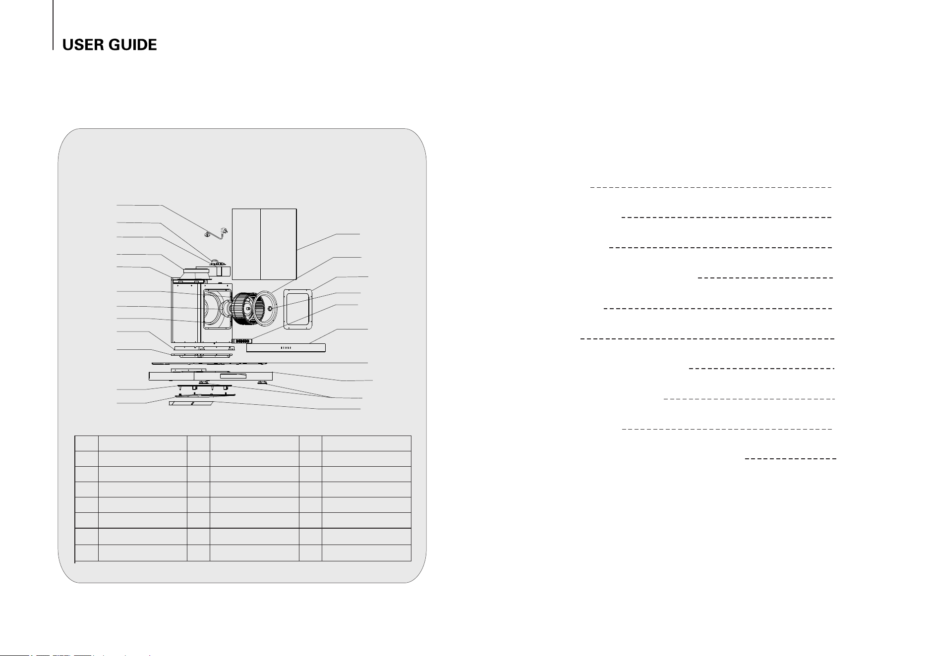
Components are only for reference, please in kind prevail.
Please stop using the hood if any exceptions occurred. No disassembly or repair by
non-specialist!
Explosive View
1
2
3
4
5
6
7
8
9
10
11
12
13
14
15
16
17
18
19
20
21
22
terminal box cover
air outlet base
motor box
joint bracket
impeller
motor
volute
power cable
switch
glass panel
upper cover plate
frame assembly
LED lamp
1
2
3
4
5
6
7
8
9
10
11
12
13
14
15
16
17
18
19
20
21
22
main board
joint plate
filter assembly
smoke deflector
chimney
air guiding ring
motor box cover
impeller cap
oil cup
2
7
1. The minimum distance from hood to cooking pot bearing surface should be
650-750mm. If the hood is installed above the gas hob, the minimum distance from
hood to cooking pot bearing surface should be at least 650mm. Please take into
consideration if big installation distance is shown in gas hob user manual.
2. Put exhaust pipe out or connect it with public cold air flue and seal the joint. Do not
discharge the burnt gas or other smoke made by other fuels into hot flue.
3. Exhaust pipe should be as short as possible (less than 1.5m), turning radius
should be as big as possible, which should be suitable for the public flue.
4. The hood must be installed horizontally and not inclined.
5. Must use reliable ground connected power socket.
Safety Caution
1
2
3
4
5
6
7
8
9
10
11
12
wood screw φ4×48
air pipe
main body
body hook
expansion pipe φ10
1
1
1
1
1
4
4
tapping screw ST3.2*8
1
anti-off board
Please check all components listed below before installation. Any missing or damage:
Please contact with retailer if it is responsible by our company or retailer;
Please contact with the nearest service center if it is responsible by users.
2
Packing List
1
13
5
14
wood screw φ12×φ4
user manual
oil cup
bar code
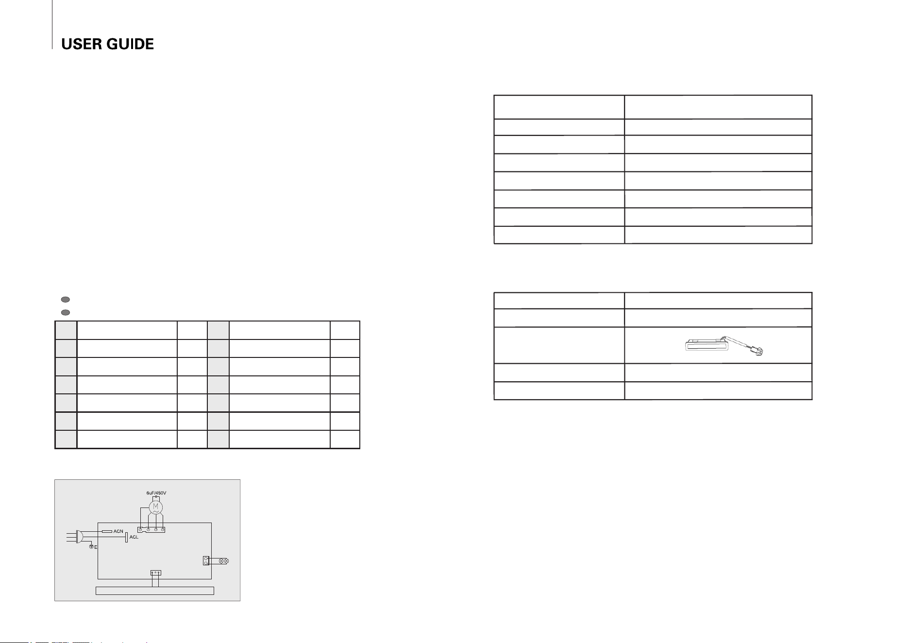
Electrical Connectivity Diagram
P3
P1
P2
blower motor
power board
(main control board)
lamp
switch panel (operating panel)
220V-240~
50-60Hz
Technical Specification
Vida X/A/90
Vida BK/A/90
Model
Power Supply
Total Power Input
Dimension(WxDxH)
220-240V50-60Hz
~,
293W (including Lamp power1.5Wx2)
Max Airflow
Boost Airflow
3
1140m /h
3
1020m /h
896x515x660(mm)
Note:56dB is sound pressure value;
70dB is A-weighted sound power level.
Noise
70dB
Motor Power Input
290W
Lamp model
Lamp dimension(WxDxH)
ON-E04-22C
91x20x17(mm)
Lamp voltage
Lamp type
LED
12VDC
Lamp max wattage
1.5W
Lamp Technical Data as follows:
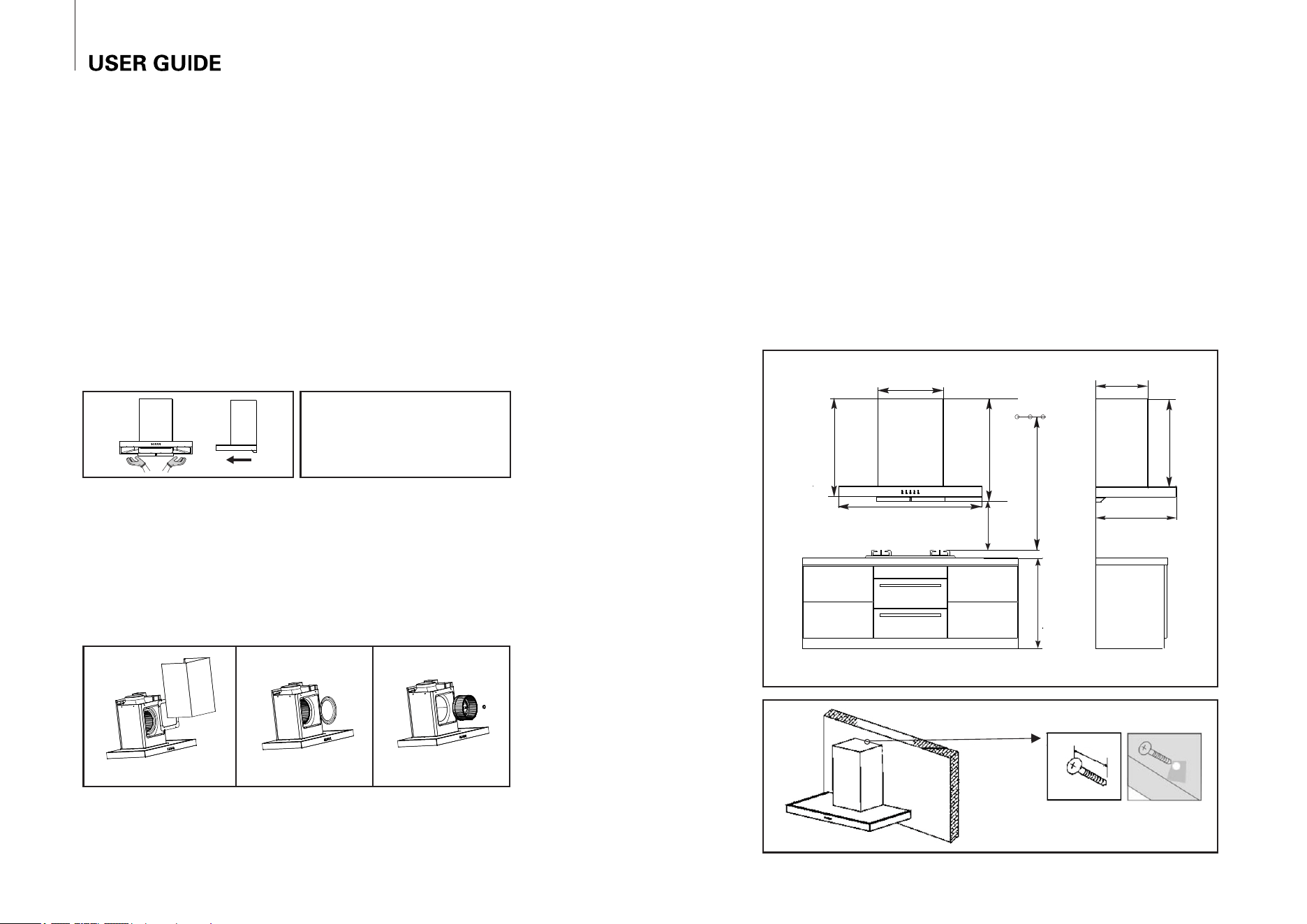
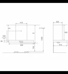
1. Use drilling tool with Ø10mm drill;
2. On the solid wall, 1255 ~ 1355mm above the kitchen surface, place the body hook
plate horizontally, to make hole 3 as the positioning template, determine the position of
drilling hole, drill hole and firmly fix the hook plate;
3. Proper install the main body and anti-off screw (wooden), and insert air outlet pipe,
fix with ST3.2×8 screw.
4. When install the upper chimney, should fix the hook in the wall at a proper height,
then pull out the upper chimney to the hook, fix with the chimney hook plate by ST4×10
self-tapping screw.
Installation
3
6
48mm
1255~1355
410
325
800
650~750
660
515
896
630
565
14. The minimum distance between the supporting surface for the cooking vessels on
the hob and the lowest part of the range hood.
15. Regulations concerning the discharge of air have to be fulfilled.
Warning: Failure to install the screws or fixing device in accordance with these
instructions may result in electrical hazards.
I. Hood Surface Cleaning:
Clean hood surface with soft cloth after each usage.
II. Oil Cup and filter Cleaning:
It is suggested to check and clean the oil cup in a fixed period. Please use soft
gauze, neutral or weak alkaline detergent, warm water to wipe the outer surface of the
oil filter, it is recommended to wipe 1~2 times a week.
According to the position shown in the figure, insert or draw the
oil cup horizontally in the direction of the guide rail of the oil plate.
III. Impeller Cleaning (Professionals only):
It is suggested to clean the impeller one time every twelve months.
Firstly, remove the chimney and motor cover plate as shown in pic (1). Then, loose
the fastening screws fixed in air guiding ring and volute as shown in pic (2). Remove
the ring and rotate the impeller cap in clockwise direction as shown in pic (3) to remove
the impeller.
(1)
(2)
(3)
4
5
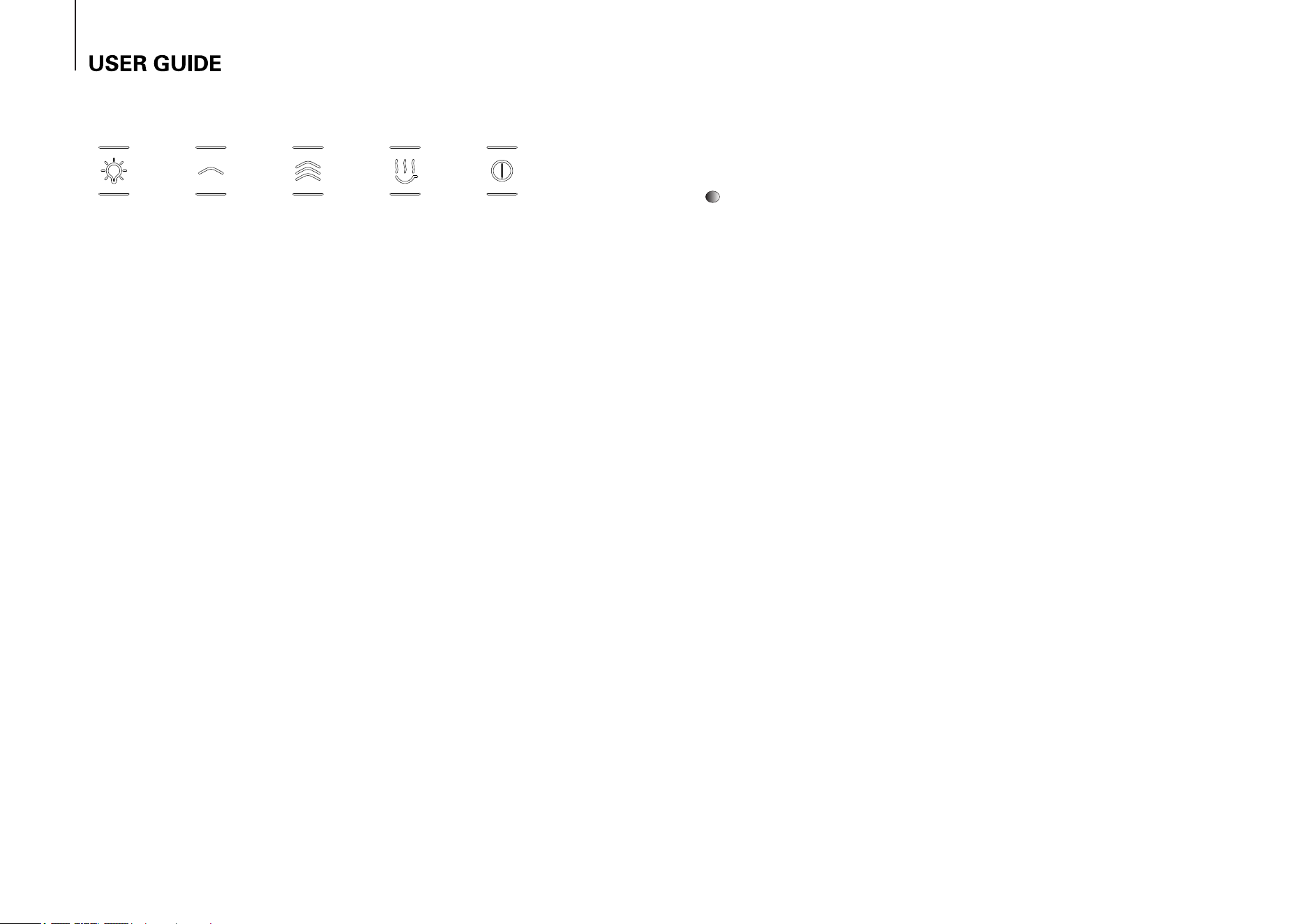
F1 - ON/OFF Timer (Automatic Shut-off/Off)
The Timer function is activated with the engine running (at any speed); after
5 minutes, the engine shuts down automatically. During the timing phase, the
display (D) shows the remaining working time, in minutes (flashing).
To stop the timer function, before these 5 minutes, press again the F1 key.
Note: By turning off the engine manually (via F3), the timer function is deactivated.
Usage
F2 - ON/OFF Lights
Allows turning ON and OFF lights.
F3 - Engine Speed Decrease/ OFF
Decreases the speed of the engine, until it shuts OFF.
ON/Engine Speed IncreaseF4 -
Enables the startup of the engine and the speed increase, from 1 to 3.
DDisplay
-
Allows the viewing of:
- the motor speed status
- the remaining time to Automatic Shut-off, when the Timer function is
activated.
Warning:
1. Please pull out power plug before maintenance.
2. No water into motor and electrical components!
3. Clean the old oil in oil cup in time. Pull out the oil cup by holding the two ends of it.
4. Replace the broken LED with similar bulb, which is not more than 1.5W.
5. Please take care of the sharp edge of metal components; Please use neutral detergent
and soft cloth or brush to clean. Avoid using organic solvent.
6. This appliance is not intended for use by persons (including children) with reduced
physical, sensory or mental capabilities, or lack of experience and knowledge, unless they
have been given supervision or instruction concerning use of the appliance by a person
responsible for their safety.
7. Children should be supervised to ensure that they do not play with the appliance.
8. If the supply cord is damaged, it must be replaced by the manufacturer, its service
agent or similarly qualified persons in order to avoid a hazard.
9. There shall be adequate ventilation of the room when the range hood is used at the
same time as appliances burning gas or other fuels (not applicable to appliances that only
discharge the air back into the room).
10. There is a fire risk if cleaning is not carried out in accordance with the instructions.
11. Do not flambé under the range hood.
12. CAUTION: Accessible parts may become hot when used with cooking appliances.
13. the air must not be discharged into a flue that is used for exhausting fumes from
appliances burning gas or other fuels (not applicable to appliances that only discharge
the air back into the room).
In order to have the best user experience and increase product life, it is suggested to
maintain the product in a fixed period.
Maintenance and Instructions