®
PN 2811813 April 2007 © 2007 Fluke Corporation. All rights reserved. Printed in U.S.A. 1
Fluke-700LTP-1
Low-Pressure Test Pump
Instruction Sheet
Introduction
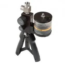
The Fluke-700LTP-1 Low-Pressure Test Pump is a
portable, dual source of vacuum and pressure. Each pump
incorporates a vacuum and pressure selector and fine
adjustment control. The pump has the following
specifications:
• Output pressure: 0 to 100 psi / 0 to 6.9 bar
• Output vacuum: 0 to -13 psi / 0 to -900 mbar
• Exposed Materials: Aluminum, silicon, neoprene,
stainless steel, Buna-N
• Adjustment: Fine volumetric pressure and vacuum
adjuster
• Dimensions: 150 mm x 100 mm
• Weight: 226 grams or .5 lbs (pump only)
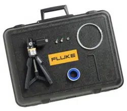
Box Contents
• Fluke 700LTP-1 Low-pressure Test Pump
• 1/8 in NPT male/female tee
• (2) 1 m hoses
• (4) 1/8 in NPT male quick connects
• (2) 1/8 NPT female to 1/4 in BSP female
• Seal Kit
• Instruction Sheet
1
2
8
3
5
6
7
4
eus01f.eps
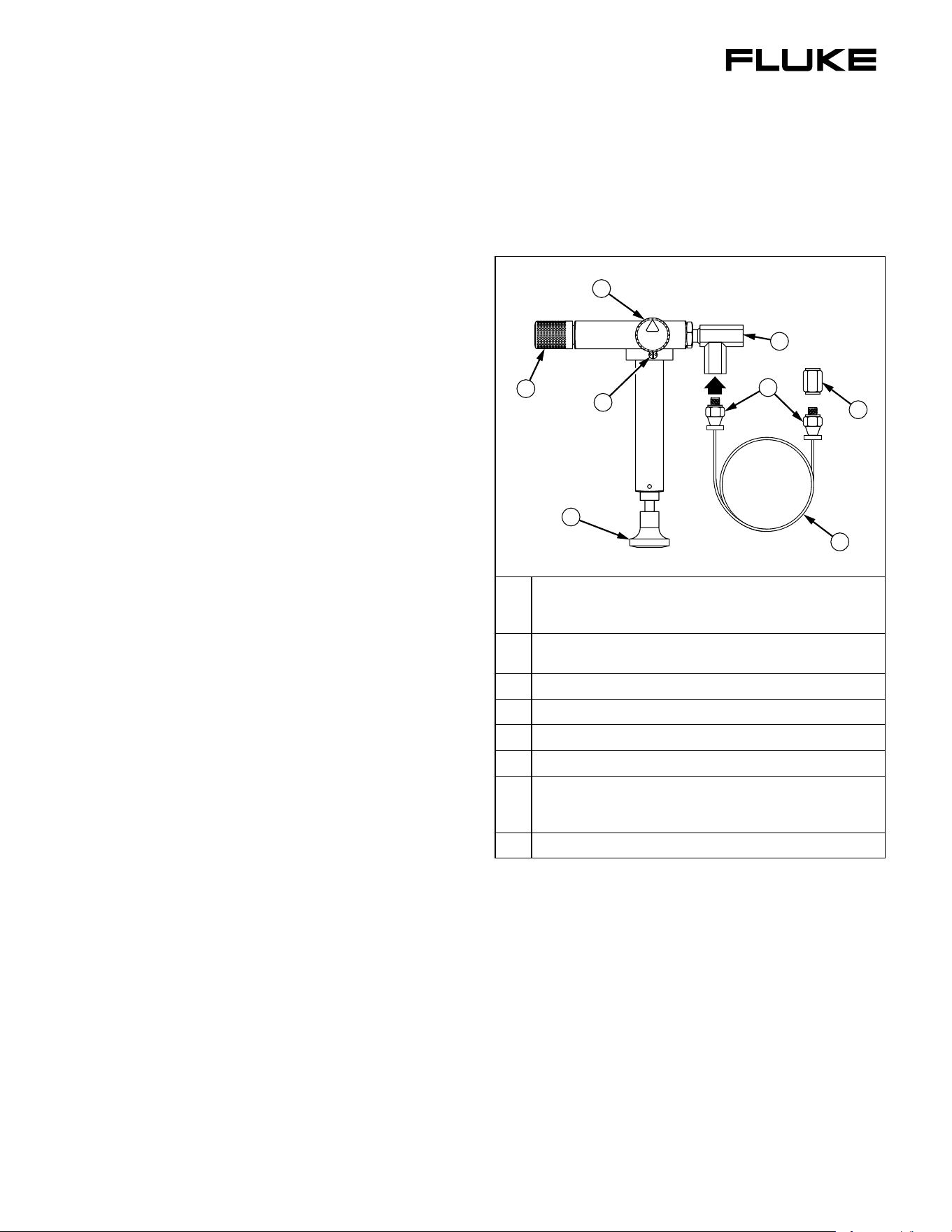
A
Pressure/vacuum release valve- Turn valve counter-
clockwise for vacuum, clockwise for pressure and
centered for release.
B
Fine adjustment control- Turn in or out to increase or
decrease pressure accordingly.
C
Master and test port tee
D
Quick-fit connectors
E
Hose
F
1/8 in NPT female to 1/4 in BSP female fitting
G
Pump Handle. If the pump has not been used for a
while, there may be some resistance on the first
stroke.
H
Cleanout ports (2)- See cleanout instructions
Figure 1. Features
Guidelines for Use
1. Connect a pressure calibrator or pressure module to
the quick-fit connector (item D) at the end of one of the
flexible hoses (item E).
2. Connect the unit under test to the quick-fit connector
(item D) at the end of the second flexible hose (item
E), choosing correct adapters (item F) and seals.
3. Turn the fine adjustment control to mid-range.
4. Set control valve to pressure.
5. Operate handle (item G) until the pressure is close to
the required value.
1.888.610.7664 sales@GlobalTestSupply.com
Fluke-Direct.com
Fluke-700LTP-1
Instruction Sheet
2
Notes
• The pressure may settle for up to one minute after
increasing pressure due to the thermodynamic
effects, settling of seals and expansion of the
flexible hose.
• On very high resolutions such as 1 mbar or 0.1
inches of water, small movements of the tubing
may result in noticeable pressure changes.
6. Turn the fine adjustment control (item B) in to increase
pressure or out to decrease pressure until required
pressure is reached.
7. Reduce pressure by careful use of the pressure release
valve (item A).
8. Achieve vacuum using the above procedure with the
pressure / vacuum selector (item A) in the vacuum
position.
When testing for leaks, you may notice that air is drawn in
or expelled from around the pressure / vacuum selector.
This is normal operation.
If the pump appears to lose pressure, then the procedure
above should be repeated, ensuring new seals are used,
adapters are tightened sufficiently and the pressure release
valve (item A) is tightened firmly. The connections to the
handheld test system are sealed with o-ring or bonded
seals and should not leak.
Pump Valve Assembly Cleaning
Instructions
Occasionally, the 700LTP-1 may not work properly due to
contamination of the internal valve assembly. Use the
following procedure to clean the valve assembly. If the
procedure does not fix the problem, a rebuild kit (2812587)
may be ordered.
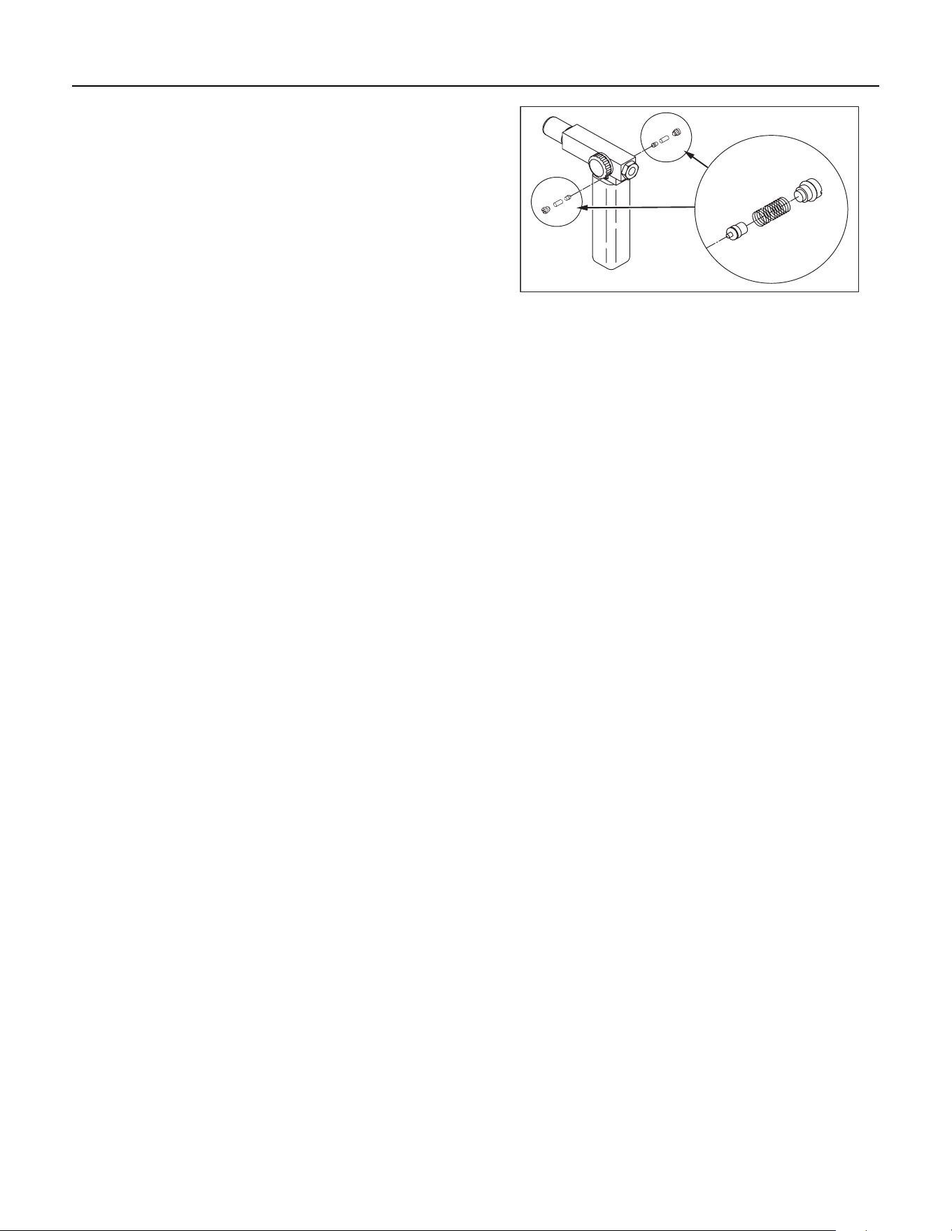
1. Using a small screwdriver, remove the 2 valve retention
caps located on opposite sides of the pump below the
pressure/vacuum switch.
2. Gently remove the spring and o-ring assembly. This
includes several small components. Remove with care.
See Figure 2.
eus02f.eps
Figure 2. Disassembly
3. Set aside the valve assemblies and clean out the valve
body using a cotton swab soaked in isopropyl alcohol.
4. Repeat the process several times using a new swab
until clean.
5. Operate the pump handles several times and recheck
for contamination.
6. Clean the o-ring assembly and the o-ring on the
retention caps with isopropyl alcohol and inspect the o-
rings closely for any damage or excessive wear.
Replacements are included in the repair kit.
7. Inspect the springs for wear or loss of tension. They
should be approximately 8.6 mm long in the relaxed
state. If shorter, they may provide sufficient sealing
tension. Replace if needed.
8. Once all parts have been cleaned and inspected,
reinstall the o-ring and spring assembly into the valve
body.
9. Reinstall the retention caps and gently tighten each
cap.
10. Seal the output port and operate the pump to at least
50 % of capacity.
11. Release the pressure and repeat several times to
ensure that the o-rings seat properly.
Replacement Parts
• Hose Assembly, Fluke PN 2815714
• Rebuild Kit, Fluke PN 2812587
11/99
1.888.610.7664 sales@GlobalTestSupply.com
Fluke-Direct.com