OWNER’S GUIDE
serial number:
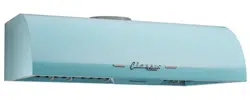
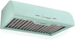
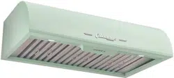
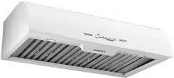
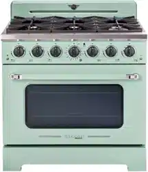
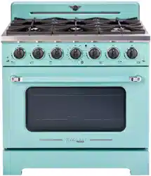
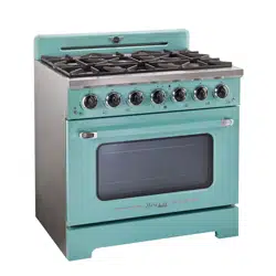
CLASSIC RETRO BY UNIQUE
36”CONVECTION GAS RANGE
MODEL NUMBERS: UGP-36CR W, UGP-36CR B, UGP-36CR LG, UGP-36CR T
4002621
DEC22V1
CLASSIC RETRO BY UNIQUE 36” CONVECTION GAS RANGE
GAS RANGE - NG & LPG CONVERTIBLE
READ AND SAVE THESE INSTRUCTIONS
Have the dealer where you purchase your new range install it or have him recommend
a qualified installer. Installation must conform with local codes. In the absence of local
codes, the installation must conform with the National Fuel Gas Code, ANSI Z223.
1-Latest Edition in the U.S.A. or the CAN/CGA B149.1 or .2 Installation Codes in Canada.
Read and save these instructions
Installation & Owner’s Manual
This manual contains information for:
• Important Safeguards
• Installation
• Use and Care
Important
TO THE OWNER OF THE RANGE: Retain this owner’s manual for future reference.
TO THE INSTALLER: Leave this owner’s manual with the range.
Certain ranges come equipped with special features. Determine from a study of
your range which of the instructions given in this booklet pertain to your range.
This booklet gives valuable instructions covering the installation, adjustment and
use of your range.
How to Obtain Service and/or Parts
When your range does not operate in accordance with the instructions in the
manual, you should contact the dealer in your immediate vicinity for service.
Or, the purchaser may contact the service organization noted on the warranty.
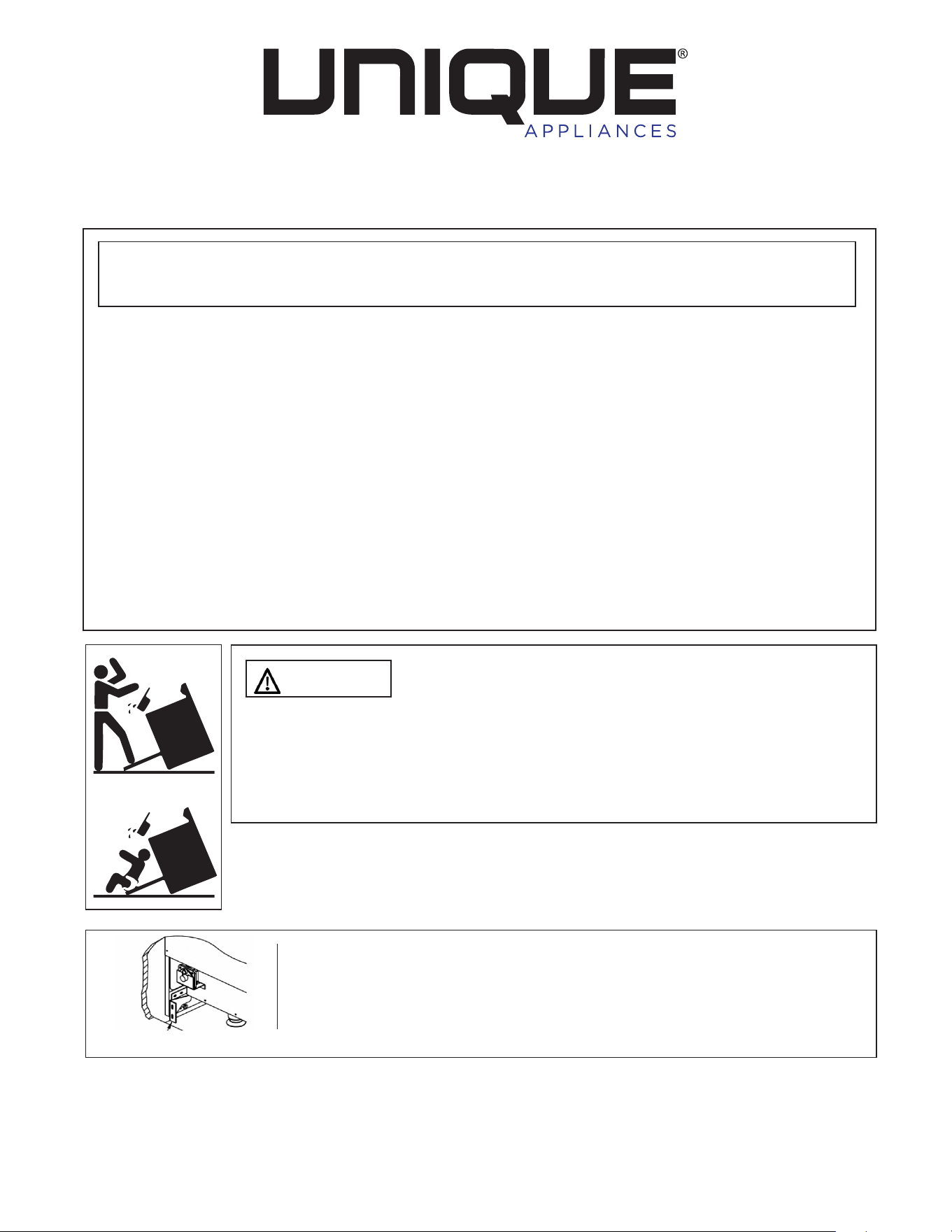
Making sure the anti-tip bracket is installed:
• Slide range forward.
• Look for the anti-tip bracket securely attached to floor.
• Slide range back so rear range foot is under anti-tip bracket.
MANUFACTURED & CERTIFIED BY
Unique Appliances
2245 Wyecroft Road #5, Oakville, Ontario, Canada L6L 5L7
Phone: 905-827-6154 Toll Free: 1-877-427-2266 Email: info@UniqueAppliances.com
www.UniqueAppliances.com
WARNING: If the information in this manual is not followed exactly, a fire or
explosion may result causing property damage, personal injury or death.
Do not store or use gasoline or other flammable vapors and liquids in the vicinity
of this or any other appliance.
WHAT TO DO IF YOU SMELL GAS
• Do not try to light any appliance.
• Do not touch any electrical switch.
• Do not use any phone in your building.
• Immediately call your gas supplier from a neighbor’s phone.
Follow the gas supplier’s instructions.
• If you cannot reach your gas supplier, call the fire department.
Installation and service must be performed by a qualified installer, service
agency or the gas supplier.
WARNING
To reduce the risk of tipping the appliance by
abnormal usage or improper door loading, the appliance must be
secured by properly installing the Anti-Tip device packed with the
appliance. To check if the device is installed and engaged properly.
Carefully tip the range forward. The Anti-Tip device should engage
and prevent the range from tipping over.
If this range is removed for any reason, service or cleaning, etc., it
must be replaced as outlined in the installation instructions before
placing the range back in operation.
X2
Range Foot Anti-tip Bracket
RANGE
BACK PANEL

4
BEFORE USING YOUR GAS RANGE . . . . . . . . . . . . . . . . . . . . 5
WELCOME . . . . . . . . . . . . . . . . . . . . . . . . . . . . . . . . . . 6
IMPORTANT SAFEGUARDS . . . . . . . . . . . . . . . . . . . . . . . . 7
SAFETY INSTRUCTIONS . . . . . . . . . . . . . . . . . . . . . . . . . . 8
INSTALLATION AND OPERATION INSTRUCTIONS . . . . . . . . . . . 10
INSTALLATION INSTRUCTIONS . . . . . . . . . . . . . . . . . . . . . . 13
HANDLE INSTALLATION INSTRUCTIONS . . . . . . . . . . . . . . . . 18
GAS CONNECTION . . . . . . . . . . . . . . . . . . . . . . . . . . . . . 19
GAS RANGE CONVERSION . . . . . . . . . . . . . . . . . . . . . . . 20
CONVERTING RANGE TO LIQUIFIED PERTOLEUM GAS . . . . . . . . 22
HOOD COMPOSITE INSTALL & USING RANGE FOR FIRST TIME . . . 28
COOKTOP OPERATION . . . . . . . . . . . . . . . . . . . . . . . . . . . 29
OVEN OPERATION . . . . . . . . . . . . . . . . . . . . . . . . . . . . . 32
BROILER OPERATION . . . . . . . . . . . . . . . . . . . . . . . . . . . 37
CARE & MAINTENANCE. . . . . . . . . . . . . . . . . . . . . . . . . . . 38
TROUBLESHOOTING . . . . . . . . . . . . . . . . . . . . . . . . . . . 45
WIRING DIAGRAM . . . . . . . . . . . . . . . . . . . . . . . . . . . . . 46
WARRANTY . . . . . . . . . . . . . . . . . . . . . . . . . . . . . . . . 48
PRODUCT REGISTRATION . . . . . . . . . . . . . . . . . . . . . . . . 49
RATING PLATE . . . . . . . . . . . . . . . . . . . . . . . . . . . . . . . 50
TABLE OF CONTENTS
5
BEFORE USING YOUR GAS RANGE
WARNING
HAVE THIS RANGE INSTALLED BY A QUALIFIED INSTALLER.
Improper installation, adjustment, alteration, services, or maintenance can cause injury
or property damage. Consult a qualified installer, service agency, or the gas supplier.
BEFORE USING YOUR GAS RANGE:
• Remove the exterior and interior packing.
• Remove the protective film on steel and aluminum parts.
• Check to be sure you have all of the parts listed below:
• 2 backsplash
• LP gas conversion packet (injectors for LP gas)
• 2 anti-tip brackets
• 2 oven racks (pre-installed)
• 7 caps and 6 burner rings (base)
• 7 knobs
• 3 cast iron grates
• 1 regulator (pre-installed)
• 8 screws for Retro backsplash
• 1 instruction/installation manual
• 1 allen key
• Clean the interior surface with lukewarm water using a soft cloth
• Have the installer show you the location of the range’s gas shut-o valve and how to
shut it o if necessary.
• Have your range installed and properly grounded by a qualified installer in
accordance with the installation instructions.
• Do not attempt to repair or replace any part of your range unless it is specifically
recommended in this manual.
• Be sure your range is correctly adjusted by a qualified service technician or installer
for the type of gas (natural or LP) that is being used.
• Do not remove permanently axed labels, warnings, or plates from the unit.
This may void the warranty.
• The installer should leave these instructions with the consumer who should retain for
local inspector’s use and for future reference.
• Please observe all local and national codes and ordinances.

6
WELCOME & CONGRATULATIONS
Congratulations on your purchase of a UNIQUE range! We are very proud of our
product – and are completely committed to providing you with the best service possible.
Your satisfaction is our #1 priority. Please read this manual very carefully. It contains
valuable information on how to properly maintain your new Unique propane range.
We know you will enjoy your new range and Thank You for choosing one of our
Unique Appliances! We hope you will consider us for future purchases.
PLEASE READ AND SAVE THESE INSTRUCTIONS
This manual provides specific operation instructions for your model. Use your range
only as instructed in this manual. These instructions are not meant to cover every
possible condition and situation that may occur. Common sense and caution must be
practiced when installing, operating and maintaining the appliance.
Record in the space provided below the Model No. and Serial No. of this appliance.
These numbers are found on the serial plate located at the bottom drawer.
Model No. ______________________
Serial No. ________________________
Purchase Date ________________________
Record these numbers for future use.
IMPORTANT: Keep a copy of your bill of sale. The date on the bill establishes the
warranty period should service be required. If service is performed, it is in your best
interest to obtain and keep all receipts.
PLEASE DO THIS NOW!
Please visit our website at https://UniqueAppliances.com/product-registration/ to
register your product.
7
READ ALL IMPORTANT SAFEGUARDS AND
ALL INSTRUCTIONS BEFORE USING THE APPLIANCE.
If the information in this manual is not followed exactly, a fire or an explosion may
result causing property damage, personal injury or even death.
Do not store or use gasoline, liquid propane cylinder or other flammable vapors and
liquids in the viicinity of this appliance.
What to do if you smell gas?
• Do not try to light any appliance.
• Do not touch any electrical switch.
• Do not use any phone in your residence.
• Immediately call your gas supplier from a neighbor’s phone.
• Follow the gas suppliers instructions.
• If you cannot reach your gas supplier, call the fire department.
For installation and service of your range product, it must be
performed by a licensed installer, an approved service agency
or your gas supplier.
The California Safe Drinking Water and Toxic Enforcement Act of 1986 (Proposition
65) requires the Governor of California to publish a list of substances known to the
State of California to cause cancer or reproductive harm. In addition, businesses must
warn customers of potential exposure to such substances.
Users of this appliance are hereby warned that the burning of gas can result in
low-level exposure to some of the listed substances, including formaldehyde, benzene,
soot and carbon monoxide. This is caused primarily from the incomplete combustion
of natural gas or LP fuel.
Properly adjusted burners will minimize incomplete combustion. Exposure to these
substances can also be minimized by properly venting the burners by opening a
window or using a ventilating hood or fan.
WARNING
WARNING
8
SAFETY INSTRUCTIONS
This is a safety alert symbol. It will alert you to potential personal or property
safety hazards. Obey all safety messages to avoid any property damage,
personal injury or death.
WARNING indicates a potentially hazardous situation which, if not avoided, could
result in serious injury or death.
CAUTION indicates a moderate hazardous situation which, if not avoided, could result
in minor or moderate injury.
CAUTION - when used without the safety alert symbol, indicates a potentially
hazardous situation which, if not avoided, could result in property damage.
IMPORTANT used for installation, operation and maintenance information that are not
related to safety.
If the information in this manual is not followed exactly, a fire or an explosion may
result causing property damage, personal injury or even death.
Do not store or use gasoline, liquid propane cylinder or other flammable vapors and
liquids in the vicinity of this appliance.
Save this manual for future references.
Definitions
WARNING
CAUTION
CAUTION
IMPORTANT
9
UNPACKING AND HANDLING
Extremely Heavy.
Proper equipment and adequate manpower when move the range to avoid personal
injury or damage to the unit or the floor. The unit is heavy and rests on adjustable steel
legs. Failure to follow this advice may result in damage or personal injury.
DO NOT lift range by the oven door handles !!
Do not store or use gasoline, liquid propane cylinder or other
flammable vapors and liquids in the vicinity of this appliance.
The installation and service of your range must be performed by a qualified installer, an
approved service agency or the gas supplier.
Gas appliances can cause minor exposure to four of these substances, namely benzene,
carbon monoxide, formaldehyde and soot, caused primarily by the incomplete
combustion of natural gas fuel. When operating your range on natural gas, the flames
from the burners should be blue in color. In addition, the flames should be stable, free
of yellow tipping, excessive noise and lifting. However, this yellow tipping should be
restricted to the primary flame kernels only. Properly adjusted burners, indicated by
a bluish rather than a yellow flame, will minimize incomplete combustion. Exposure
to those substances can be minimized by venting with an open window or use of a
ventilation fan or hood.
NOTICE: Never keep pet birds in the kitchen. birds have a very sensitive respiratory
system. Fumes released from cooking oil, fat, margarine or overheated non-stick
cookware may be harmful or fatal to birds.
ELECTRICAL GROUNDING INSTRUCTIONS
IMPORTANT
This indoor cooking appliance is equipped with a three-prong (grounding) plug for
your protection against shock hazard and should be plugged directly into a properly
grounded three-pronged receptacle. DO NOT cut or remove the grounding prong from
this plug.
SAFETY INSTRUCTIONS
WARNING
WARNING
10
INSTALLATION AND OPERATION INSTRUCTIONS
To ensure proper and safe operation, read all instructions before using the product.
Install or locate the product only in accordance with the provided Installation
Instructions.
• All servicing should be performed to a qualified technician.
• Do not attempt to adjust, repair, service or replace any part of your appliance
unless it is specifically recommended in this guide.
• Do not use the range for warming or heating the room.
• Do not leave children alone or unattended in the area where the range is in use.
Never allow them to sit or stand on any part of the range. Do not let children play
with the range.
• Have the technician show you the location of the gas shut o valve and how to
shut it o in an emergency situation.
• Always disconnect power to appliance before any type of servicing.
• Do not use abrasive or caustic cleaners or detergents on this appliance. They may
cause permanent damage to the surface.
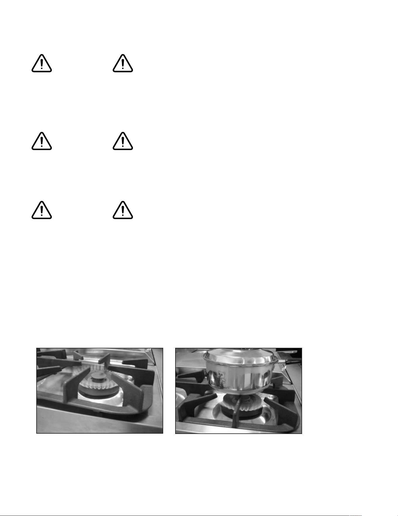
• When cooking, set the burner controls so that the flame heats only the bottom of
the utensil and does not overlap at the sides of the utensil.
• Utensils (pots and pans) that conduct heat slowly, i.e. glass pots, should be used in
conjunction with burner flames at a low or medium setting.
• Turn o all controls and wait for appliance parts to cool down before touching
them. Do not touch the burner grates or surrounding areas until cool.
• Do not use water on grease fires.
• Clean appliance with caution.
• Always turn pot handles to the side or back of the range. Do not turn handles
towards the area where they can be easily burned. Handles should not extend over
the adjacent burners.
• Use the range only for cooking tasks as outlined in this manual. When using the
range, do not touch the grates, burner caps, burner bases, or any other parts in
proximity to the flame. These components may be hot enough to cause burns.
• Use dry pot holders. Moist or damp pot holders on hot surfaces may result in burns
from steam.
WARNING
11
INSTALLATION AND OPERATION INSTRUCTIONS
IMPORTANT
Keep appliance area clear and free from combustible materials, gasoline, and other
flammable vapors.
Gas Supply Requirements
Installation of this range must conform with local codes, or in the absence of local codes,
the National Fuel Gas Code, ANSI Z223.1 I NFPA 54. In Canada, installation must conform
to the current natural Gas Installation /code, CAN 1-1.1-M81 and with local codes where
applicable. This range has been design-certified according to ANSI Z21.1b-2012 latest
edition.
A statement of the maximum gas supply pressure in accordance with the inlet pressure
rating of the gas appliance pressure regulator supplied.
MINIMUM GAS SUPPLY PRESSURE TO APPLIANCE FOR LP GAS: 10 IN.W.C.
(Do not exceed 14 IN.W.C.)
MINIMUM GAS SUPPLY PRESSURE TO APPLIANCE FOR NG: 6 IN.W.C.
Do not obstruct the flow of combustion air into the range and ventilation air away from
the range.
Ventilation: it is recommended that the unit be operated with an oven head, vented
exhaust hood of sucient size and capacity.
Before installing the range, you must locate and secure the included anti-tip bracket to the
wall for your range.
The use of cabinets for storage above the appliance may result in a potential fire hazard.
Combustible items may ignite; metallic items may become hot and cause burns. If a
cabinet storage is to be provided, the risk can be reduced by installing a range hood that
projects horizontally a minimum of 5” (12.7cm) beyond the bottom of the cabinets.
The appliance shall not be used for space heating. This information is based on safety
considerations. All openings in the wall behind the appliance and in the floor under the
appliance shall be sealed.
CAUTION
WARNING
INPUT PRESSURE OUTPUT PRESSURE
NG
7inch 7inch
LPG
11inch 10inch
12
CARBON MONOXIDE WARNING
Carbon Monoxide is a possible danger when using any gas powered appliance.
All gas appliances MUST be installed by a licensed professional who is familiar with
the Carbon Monoxide levels appropriate for each appliance.
The American Gas Association publishes CO emissions for appliances and heating
equipment through the ANSI Std. Z21.1
The EPA reports that a maximum CO (Carbon Monoxide) level of 9 PPM over a 24
hour period is the residential interior ambient level standard.
(A properly ventilated home will have a normal CO level of less than 5 PPM.)
NON-VENTED GAS COOKING APPLIANCES:
Non-vented gas cooking appliances in a residential application are normally used
for a short period of time. The CO generated during the operation will disperse to
the air in the home and be purged to the outside through the normal air exchange.
13
INSTALLATION INSTRUCTIONS
Be sure appliance is properly installed and grounded by a qualified technician.
It is the responsibility of the technician to make certain that your range is properly
installed. Situations caused by improper installation are not covered under the
warranty. Any expenses incurred due to such situations will not be paid by the
manufacturer of the appliance.
If this range is removed for any reason, (eg. service
or cleaning), it must be replaced as outlined before
placing the range back in operation.
Levelling a Free-Standing Range
All free-standing ranges must be level to obtain proper
cooking results. The leveling legs should be screwed
into the corner brackets. Place pan or measuring cup
partially filled with water or a level on the oven rack.
Adjust the leveling legs until the range is level. The top
of the side panels should be level with the counter top.
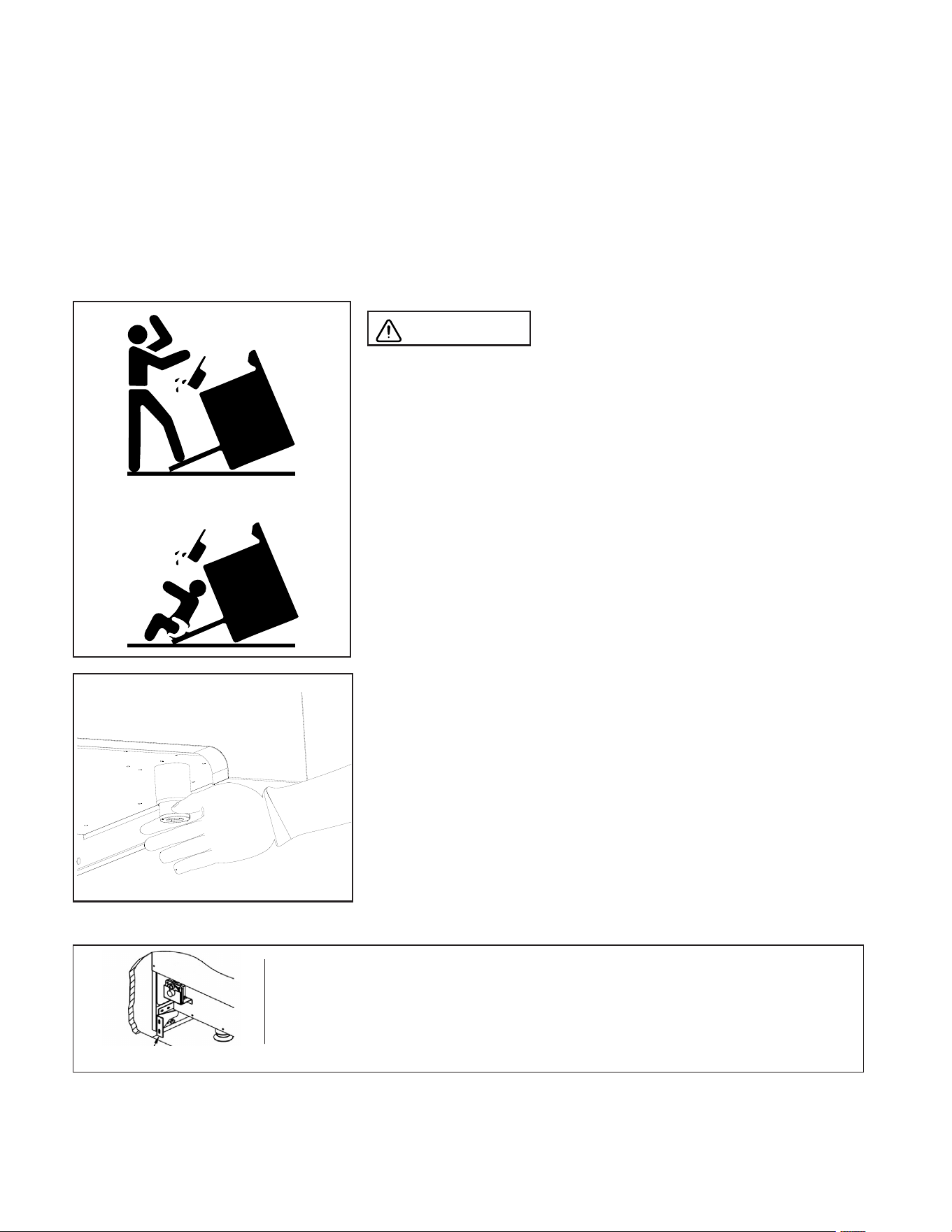
WARNING
A child or adult can tip the range
and be killed. Install the anti-tip device to the structure
and/or the range. Verify the anti-tip device has been
properly installed and engaged. Engage the range
to the anti-tip device by ensuring the anti-tip device
is re-engaged when the range is moved. Re-engage
the anti-tip device if the range is moved. Do not
operate the range without the anti-tip device in place
and engaged. See installation instructions for details.
Failure to do so can result in death or serious burns to
children or adults.
Making sure the anti-tip bracket is installed:
• Slide range forward.
• Look for the anti-tip bracket securely attached to floor.
• Slide range back so rear range foot is under anti-tip bracket.
X2
Range Foot Anti-tip Bracket
14
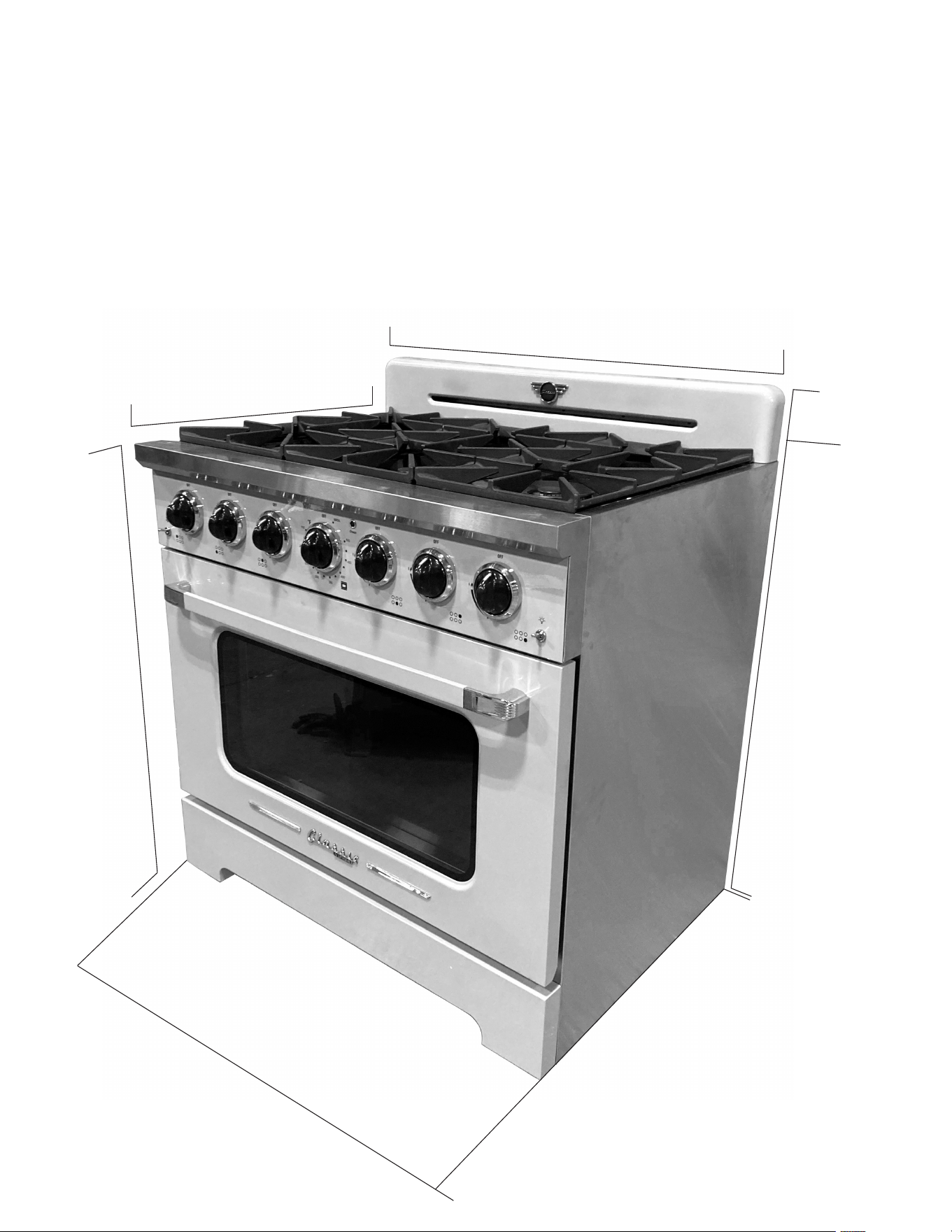
27.3”
44.25”
36”
41”
37”
Depth with Door Open
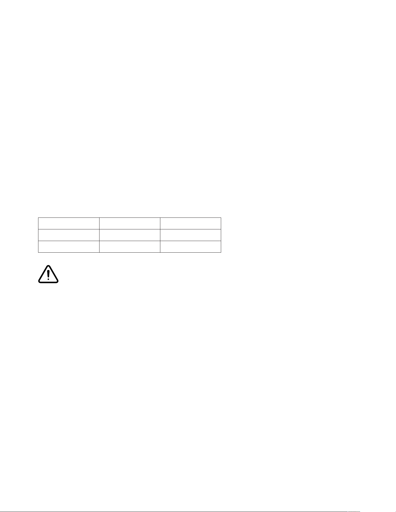
INSTALLATION INSTRUCTIONS
Dimensions and Clearances
The range may be installed flush to the rear wall. You may install a non-combustible
material on the rear wall above the range and up to the vent hood. It is not necessary to
install non-combustible materials behind the range below the counter top height.
The minimum distance from the side of the range above the counter top to combustible
sidewalls must be at least 10 inches.
36”
(For low profile
backsplash)
(For larger backsplash)
15
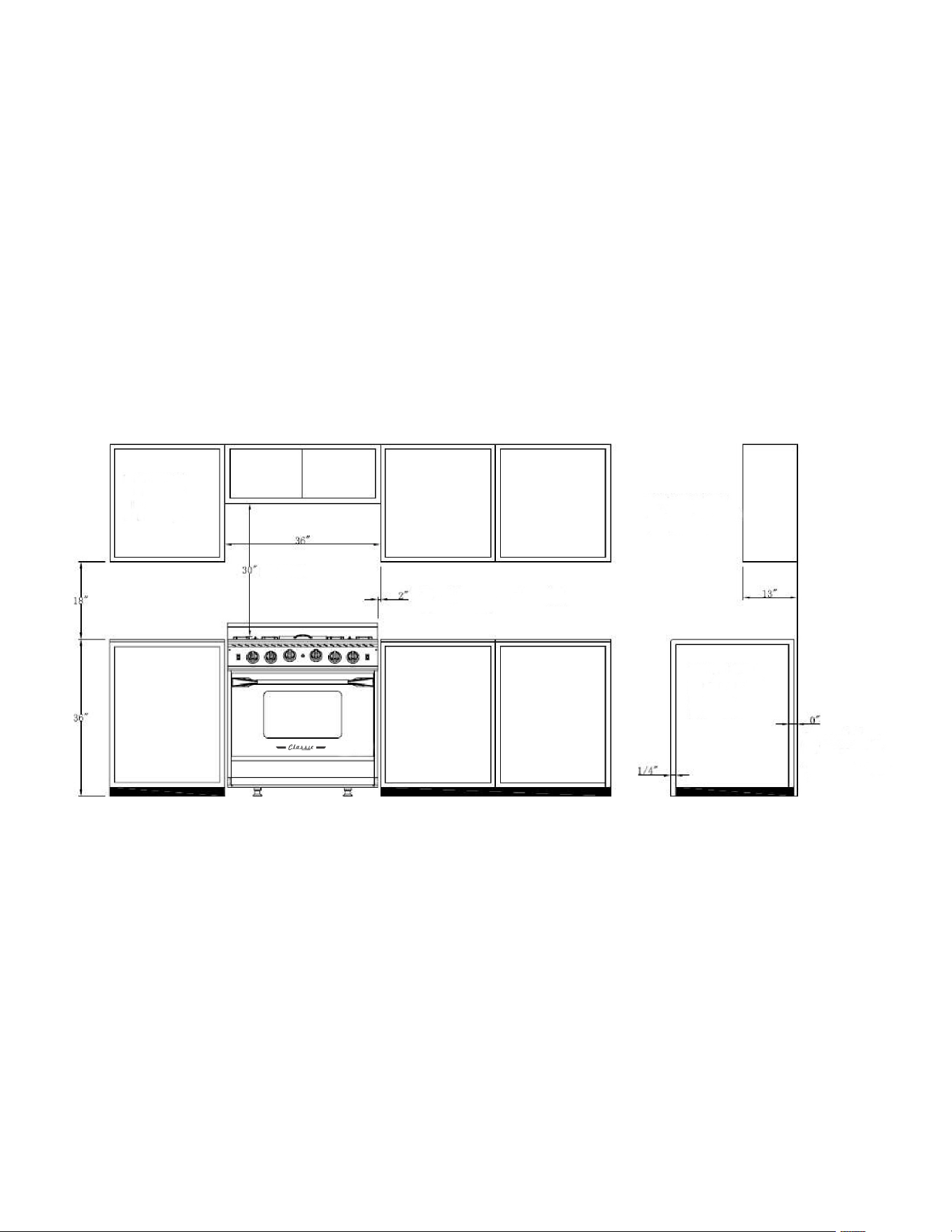
INSTALLATION INSTRUCTIONS
Minimum to
cabimets on
either side
of the range
Minimum
To wall on either side sealed
burner models
Maximum depth
for cabinets above
countertops
Front edge of
the range side
panel forward
from cabinet
To countertops
below cooktop
and at the range
back
16
INSTALLATION INSTRUCTIONS
Electric Power Supply Requirements
Your range must be electrically grounded in accordance with local codes or, in the
absence of local codes, in accordance with the National Electrical Code (ANSI/NFPA 70,
latest edition). In Canada, electrical grounding must be in accordance with the current
CSA C22. l Canadian Electrical Code Part 1 and/or local codes. A copy of this standard
may be obtained from: National Fire Protection Association, 1 Batterymarch Park,
Quincy, Massachusetts 02269-9101.
The power supply must be the correct polarity. Reverse polarity will result in continuous
sparking of the electrodes, even after flame ignition. If there is any doubt as to whether
the power supply has the correct polarity or grounded, have it checked by a qualified
electrician.
Use 120V, 60Hz, and properly grounded branch circuit protected by a 15-amp or
20-amp circuit breaker or time delay fuse.
Electrical Grounding Instructions: this indoor gas cooking appliance is equipped with
a three-prong (grounding) plug for your protection against shock hazard and should
be plugged directly into a properly grounded three-pronged receptacle.
Do Not cut or removes the grounding prong from the plug.
Caution Label all wires prior to disconnection when servicing controls. Wiring errors
can cause improper and dangerous operation. Verify proper operation after servicing.
Grounding
• The power cord is equipped with a three-prong (grounding) plug which mates with
a standard three-prong grounding wall receptacle to minimize the possibility of
electrical shock hazard from the range.
• All cord connected appliance shall include instructions relative to location of the
wall receptacle and a warning to the user to disconnect the electrical supply before
serving the appliance.
• Where a standard two-prong wall receptacle is encountered, it is the responsibility
and obligation of the customer to have it replaced with a properly grounded three
prong wall receptacle. Do not cut or remove the grounding prong from the power
cord.
WARNING
17
INSTALLATION INSTRUCTIONS
Backsplash Option 1
Backsplash Option 2
1. Align the backsplash to the rear
part of the cooktop as shown in the
diagram.
2. Secure the backsplash to the
cooktop from the back using the
8 Phillips head screws provided as
shown in the diagram.
HOW TO INSTALL THE BACKSPLASH
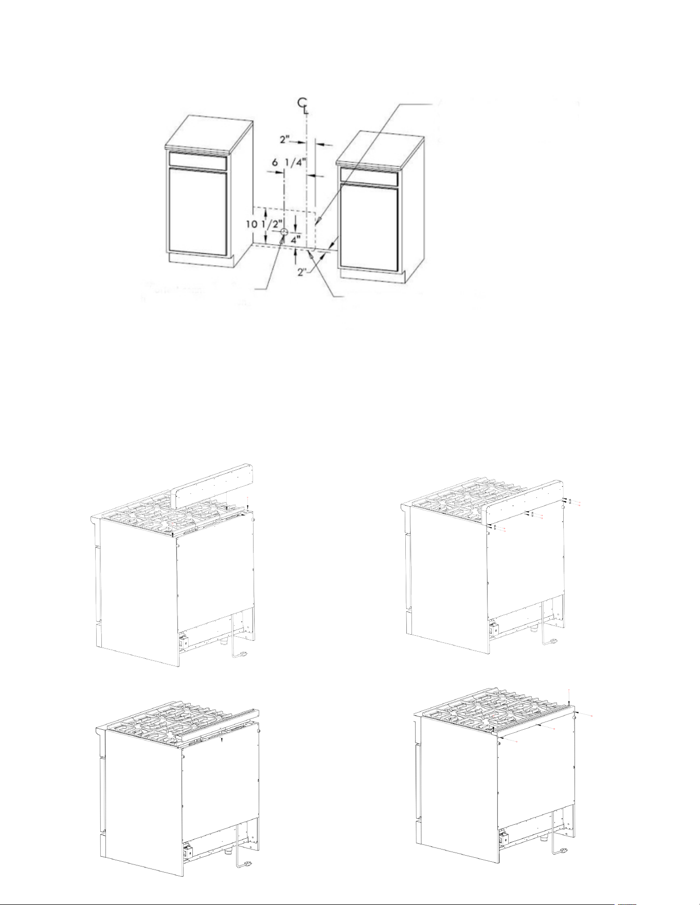
Shortest connection from
hard pipe stub location
to range hook-up
Area allows for flush installation
with through-the-floor connection
of pipe stub/shut-o valve
Area allows for flush installation
with through-the-wall connection
of pipe stub/shut-o valve and rear
wall 120V outlet.
18
HANDLE INSTALLATION INSTRUCTIONS
�
]
-
--
-
----
-----
----
---
-
---
-
F
---
�
---
�
----
F
---
�
---
�
�
....
1
____________ __________ _
----
----
-----
-----
-----
.
. .
.
.
.
�
]
-
--
-
----
-----
----
---
-
---
-
F
---
�
---
�
----
F
---
�
---
�
�
....
1
____________ __________ _
----
----
-----
-----
-----
.
. .
.
.
.
�
]
-
--
-
----
-----
----
---
-
---
-
F
---
�
---
�
----
F
---
�
---
�
�
....
1
____________ __________ _
----
----
-----
-----
-----
.
. .
.
.
.
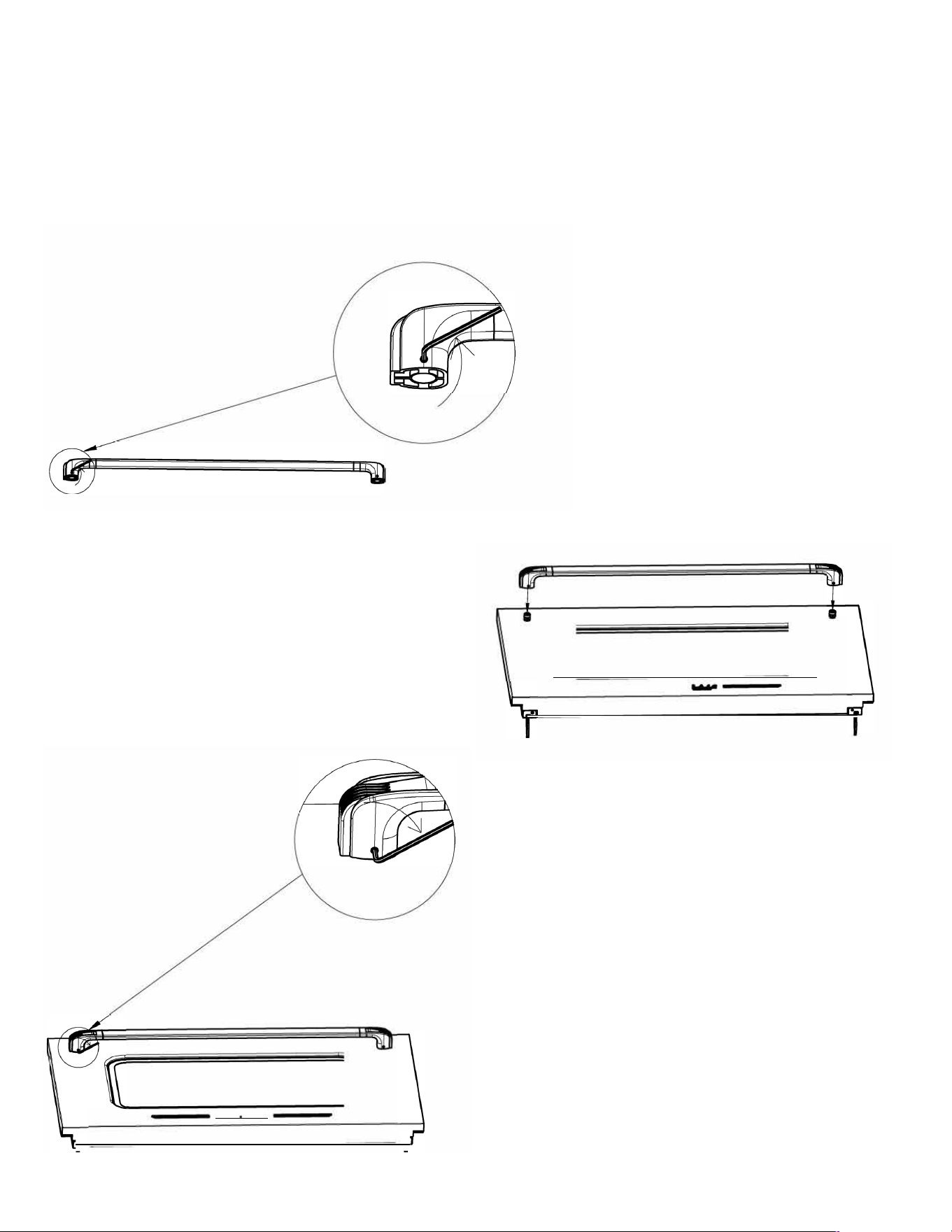
Step 2: Insert the assembled handle
onto the range door.
Step 1: Use the allen key that is included
with your range to loosen the screws on
the bottom of the handles.
Step 3: Use the allen key that is included
with your range to tighten the screws on
the bottom of the handles.

19
Connect Range to Gas Supply
• Install a manual gas line shut-o valve in the gas line in an easily accessed location
outside the range in the gas piping external to the appliance for the purpose of
turning on or shutting o gas to the appliance.
• Install male 1/2” flare union adapter to 1/2” NPT internal thread elbow at inlet of
regulator. On models equipped with standard twin burners, install the male pipe
thread end of the 1/2” flare union adapter to the 1/2” NPT internal thread at inlet of
pressure regulator. Use a wrench on the regulator fitting to avoid damage.
• Install male 1/2” or 3/4” flare union adapter to the NPT internal thread of the
manual shut-o valve, taking care to secure the shut-o valve to keep it from
turning.
• For Natural Gas (NG) the gas supply input pressure for checking the regulator
setting is 7inches and the output pressure is 5inches. For Liquid Propane Gas
(LPG) the gas supply input pressure for checking the regulator setting is 11inches
and the output pressure is 10inches.
• Connect the flexible gas line connector to the regulator on the range.
Position range to permit connection at the shut-o valve.
• When all connections have been made, check that all range controls are in the “o”
position and turn on the main gas supply valve.
• Leak testing of the appliance shall be conducted according to the manufacture’s
instructions. Use some soap water (50% water and 50% soap) or a leak detector
at all joints and connections to check for leaks in the system. Do not use a flame to
check for gas leaks.
GAS CONNECTIONS
20
To convert application and/or adjust from NG to LPG
The range is set for use with Natural Gas (NG). The factory setting is indicated on
the serial plate. When set for Natural Gas operation, the pressure regulator will
regulate the gas to 4” water column pressure. When set for Liquid Propane Gas (LPG)
operation, the pressure regulator will regulate the pressure to 11” water column.
Natural Gas to Liquid Propane Gas Conversion
The conversion kit must be installed by qualified service agency.
WARNING: Please ensure before beginning converting the appliance that the gas
supply is shut o and the electrical connection is disconnected. Failure to do can
result in injury or property damage.
Determine the combination of top burners that are featured on your range.
Identify the parts you need from this kit to complete the L.P. conversion.
When burners are converted from natural to L.P. the BTU ratings are as follows:
GAS RANGE CONVERSION
“This conversion kit shall be installed by a qualified service agency in accordance
with the manufacturer’s instructions and all applicable codes and requirements of the
authority having jurisdiction. If the information in these instructions is not followed
exactly, a fire, explosion or production of carbon monoxide may result in property
damage, personal injury or loss of life. The qualified service agency is responsible for
the proper installation of this kit. The installation is not proper and complete until the
operation of the converted appliances is checked as specified in the manufacturer’s
instructions supplied with the kit.”
Rear Left Burner 9,000 BTU L.P. Gas [1.0mm]
Rear Mid Burner 9,000 BTU L.P. Gas [0.90mm]
Rear Right Burner 12,000 BTU L.P. Gas [1.0mm]
Front Left Burner 15,000 BTU L.P. Gas [1.16mm]
Front Mid Burner 6,000 BTU L.P. Gas [0.74mm]
Triple Crown Burner 20,000 BTU L.P. Gas [0.89*2+0.53mm]
Broil Burner 10,000 BTU L.P. Gas [0.94mm]
Oven Burner 22,000 BTU L.P. Gas [1.40mm]

21
2mm Allen Wrench
3/8 & 1/2 & 5/8” [19mm] Open End Wrench
1/8” Wide Flat Blade Screwdriver
Philips Screwdriver
7mm Nut Driver
1/4 Nut Driver
Adjustable Wrench
The original orifices are Natural Gas:
Tools Required for L.P. Conversion:
GAS RANGE CONVERSION
Rear Left Burner 9,000 BTU [1.36mm]
Rear Mid Burner 9,000 BTU [1.36mm]
Rear Right Burner 12,000 BTU [1.57mm]
Front Left Burner 15,000 BTU [1.79mm]
Front Mid Burner 6,000 BTU [1.07mm]
Triple Crown Burner 20,000 BTU [1.36*2 + 0.73mm]
Broil Burner 10,000 BTU [1.42mm]
Oven Burner 22,000 BTU [2.13mm]
*Note: For operation at elevations above 2000ft., appliance rating shall be reduced
at the rate of 4% for each 1000 ft. above sea level
IMPORTANT:
After replacing the natural gas to LP orifices, be sure to keep the original factory
installed natural gas orifices for future range conversion back to natural gas.
22
INSTRUCTIONS FOR CONVERTING RANGE TO OPERATE ON
LIQUEFIED PETROLEUM GAS
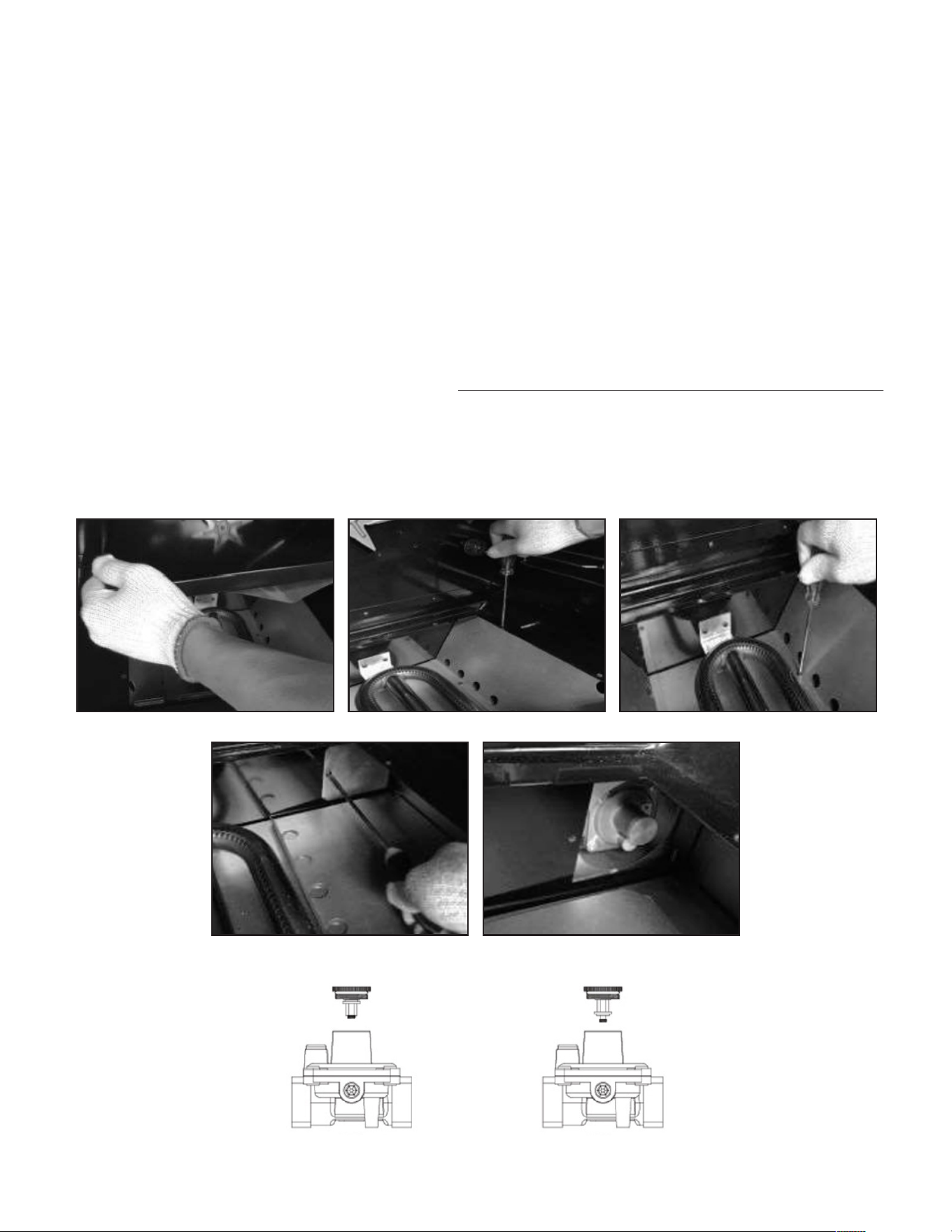
1. Convert the Pressure Regulator
To access the gas regulator, pull the range away from the cabinet wall.
The gas regulator is located at the bottom right corner of the range.
a. Electrical shock hazard can occur and result in injury or death.
Disconnect electrical power to the range before servicing. Do not remove regulator
or allow it to turn during servicing.
b. Unscrew the cap from the regulator. Do not remove the spring from the regulator.
c. Unscrew the insert from the cap and turn it over so the longer stem is facing the
cap. Replace insert on the cap. Replace the cap on the regulator.
1. 2.
4.
Position for NG Position for LP
3.
5.
23
INSTRUCTIONS FOR CONVERTING RANGE TO OPERATE ON
LIQUEFIED PETROLEUM GAS
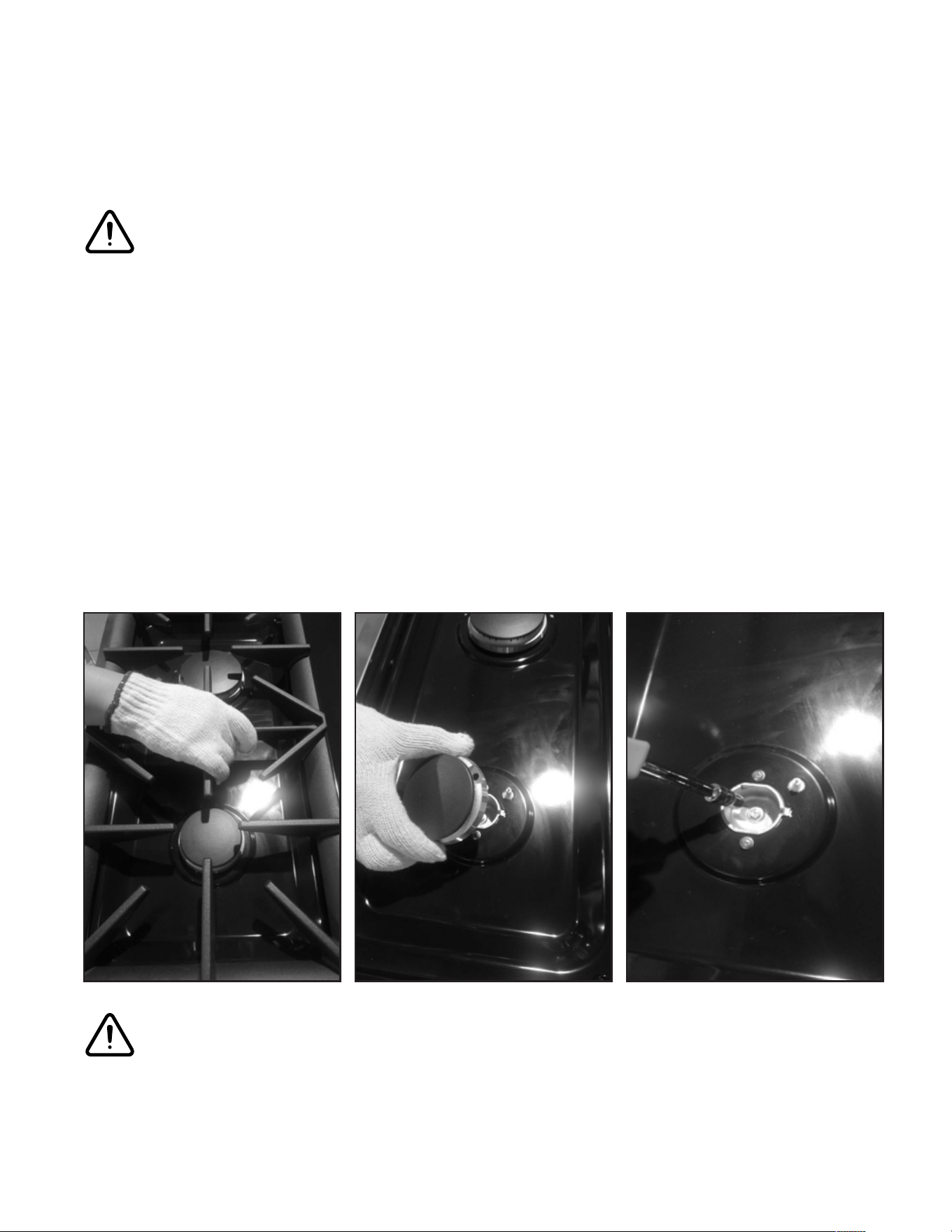
2. Convert Top Burner for LP/Propane Gas
Save the natural gas orifices removed from the appliance for possible future
conversions to natural gas. You should use the following process to convert to Natural
gas. Take extra care when handling steel parts.
a. Remove cooking grates, burner caps and inner burner rings.
b. Lift o outer burner heads and burner bases.
c. Remove the factory installed natural gas orifices from the center of the orifice
holders using a 7mm nut driver. Remember to keep the original natural gas orifices
for future conversions back to natural gas. Replace the LP orifice in each orifice
holder. Tighten each orifice until snug. Use caution not to over tighten.
1. 2. 3.
CAUTION
CAUTION
Care should be taken when removing and replacing gas components.
Use proper support to prevent damage to components.
24
INSTRUCTIONS FOR CONVERTING RANGE TO OPERATE ON
LIQUEFIED PETROLEUM GAS
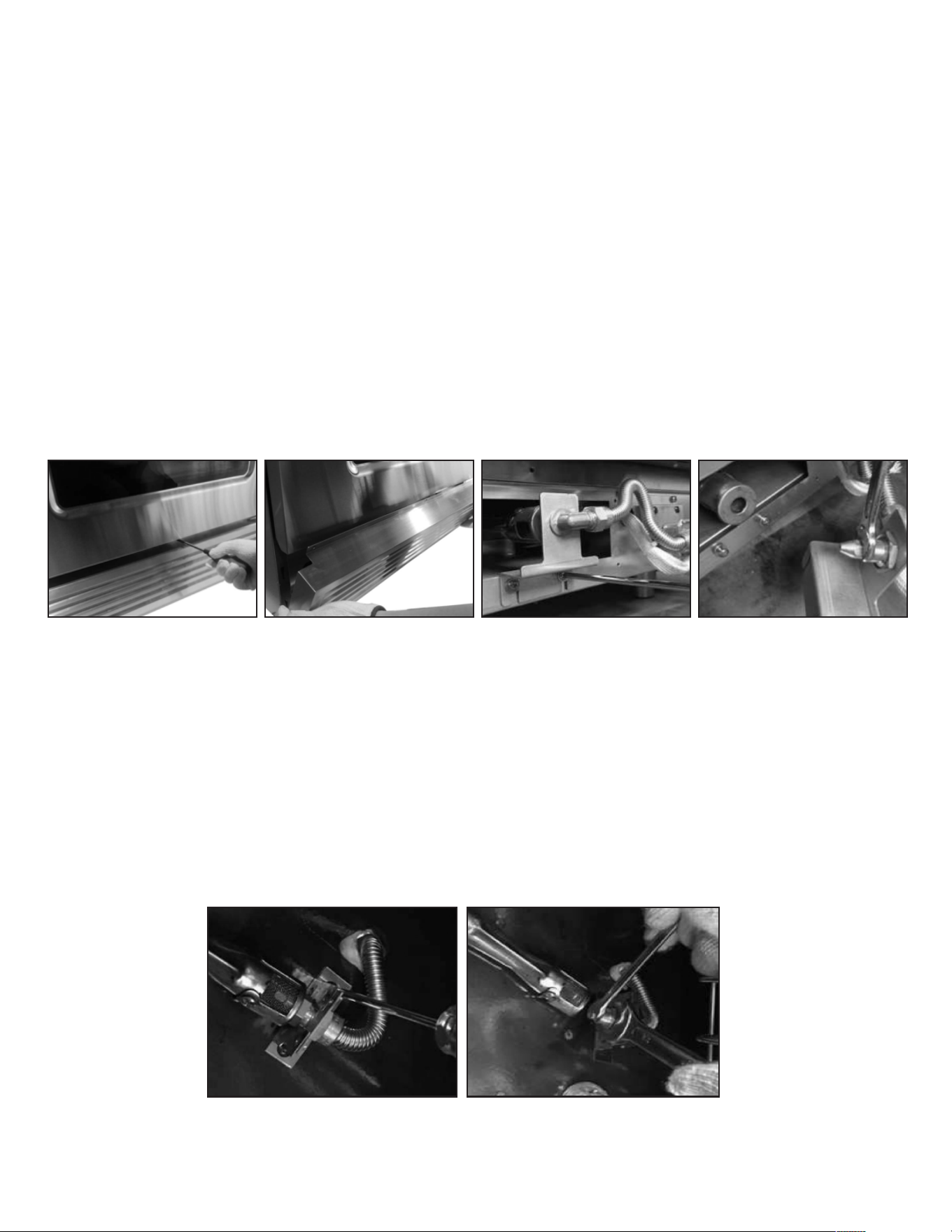
3. Convert Oven Burner Orifice for LP/Propane Gas
a. Remove 3 screws between the kick panel and the oven door (ref below 1.). Hold
the toe kick panel on both ends and slowly pull upwards and out towards your self.
(ref below 2.).
b. Remove 2 screws which hold the orifice bracket and locate the orifice
(ref below 3.). Remove orifice using an adjustable wrench (ref below 4.). Replace
with oven burner orifice, size 1.32mm and tighten. Replace the orifice bracket,
aligning the new orifices into the air shutter of the oven burner.
4. Convert Broil Burner Orifice for LP/Propane Gas
a. Remove 2 screws which fixing the orifice bracket and locate the orifice.
b. Using a 5/8” or 19mm open wrench, remove the gas line from the orifice holder.
Using a 1/2” open wrench, remove the orifice from the orifice holder.
Replace with oven broiler orifice size 0.94mm.
1.
1.
2.
2.
3. 4.
25
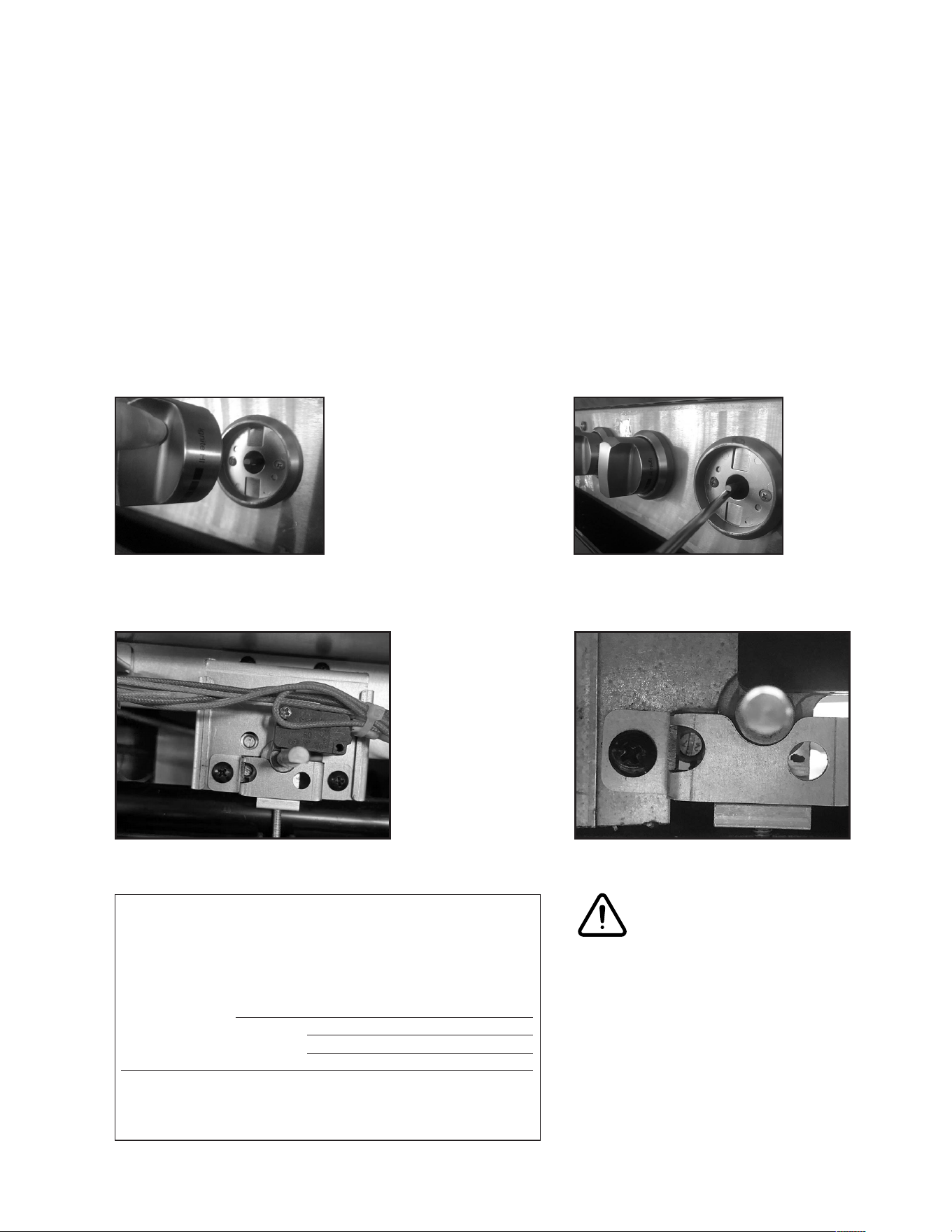
5. Convert Gas Valves for LP/Propane Gas
a. Remove control knobs (ref below 1.).
b. Turn the top burner valve fully counterclockwise (minimum position), then proceed
to adjust the adjustment screw clockwise for a smaller flame and counterclockwise
for a bigger flame. (ref below 2.).
1. 2.
CAUTION
Care should be taken when
removing and replacing gas
components. Use proper support
to prevent damage to components.
Large right front burner
(two adjustment ports)
All other burners
(one adjustment port)
INSTRUCTIONS FOR CONVERTING RANGE TO OPERATE ON
LIQUEFIED PETROLEUM GAS
This cooking range can be used with LPG(Liquid Propane Gas)
and NG (Natural Gas). It is shipped from the factory adjusted
for use with NG. Conversion nozzles are included in this plastic
bag. Follow the instructions in the manual (page 20 to 27) for gas
conversion.
Gas range model:
This range was converted on:
(day/month/year)to LPG by:
(name and address of company making this conversion) . which
accepts the liability that this conversion has been properly made.
LPG Supply Pressure 10” w.c.
26
6. Reconnect Gas and Electrical Supply to Range
Leak testing of the appliance shall be conducted according to the installation
instructions provided with the range.
Checking for Manifold Gas Pressure
If it is necessary to check the manifold gas pressure, remove the burner cap, inner
ring, outer burner head and burner base of the right front top burner and connect a
manometer (water gauge) or other pressure test device to the burner orifice. Use a
rubber hose with inside diameter of approximately 1/4“ and hold the end of the tube
tight over the orifice.
Turn the gas valve on. For a more accurate pressure check, have at least two (2) other
top burners burning. Be sure that the gas supply (inlet) pressure is at least one inch
above the specified manifold pressure.
Do not use a flame to check for gas leaks
a. Disconnect the range and its individual shut-o valve from the gas supply piping
system during any pressure of that system at test pressures greater than 14” of
water column pressure (approximately 1/2“ psig)
b. The appliance must be isolated from the gas supply piping system by closing its
individual manual shut-o valve during any pressure testing of the supply system
at test pressure equal to or less than 14” water column pressure
INSTRUCTIONS FOR CONVERTING RANGE TO OPERATE ON
LIQUEFIED PETROLEUM GAS
CAUTION
INPUT PRESSURE OUTPUT PRESSURE
NG
7inch 7inch
LPG
11inch 10inch

27
7. Air Shutter Oven Burner
The air shutter for the oven burner may need adjustment, especially if the unit has
been converted for use with LP/Propane gas. The approximate flame length of the
oven burner is 1 or 1.5 inch (distinct inner blue flame).
To determine if the oven burner flame is proper:
a. With the kick plate removed, set the oven to bake at 350 °F and observe the flame.
If the flame is yellow in color, increase the air shutter opening size. If the flame is
blue lifting away from the burner, reduce the air shutter opening size.
b. Turn o oven and allow it to cool before adjusting the air shutter. To adjust, loosen
the lock screw, reposition the air shutter and tighten the lock screw. Retest the
burner by repeating the steps above. When the burner flame is a distinct blue color
burning steadily, the air shutter is adjusted correctly.
INSTRUCTIONS FOR CONVERTING RANGE TO OPERATE ON
LIQUEFIED PETROLEUM GAS
28
The bottom of the hood should be 30”min to 36” above the counter top. This would
typically result in the bottom of the hood being 66” to 72” above the floor. These
dimensions provide safe and ecient operation of the hood.
After Installation:
a. Check ignition of cooktop burners.
b. Check the air shutter adjustment - sharp blue flame, with no yellow tipping or
lifting flames. Check ignition of oven burner.
c. Visually check tubular burner (oven burner) re-ignition to be sure both rows of
burner ports are relighting each time.
d. Check for gas leaks at all gas connections
(using a gas detector, never a flame).
Check oven bake and convection bake function.
Using Oven for First Time
When using the appliance or the first time, the oven and broiler burners should be
turned on the burn o the manufacture oils. Turn the oven on the 450°F [230 °C] for
20 to 30 minutes, then turn the oven control knob to “Broil” for the same length of
time. It is recommended to turn on the ventilator above the range at this time.
Before Baking or Broiling the oven and broiler should be turned on to burn o the
manufacturing oils. Turn the oven onto 450°F [230°C] for 2O to 30 minutes; then
turn the broiler to “Broil” for the same length of time. You may wish to turn on the
ventilator above your range at this time.
HOOD/COMPOSITE OVERLAY INSTALL
& USING OVEN FOR FIRST TIME
WARNING
WALL INSTALLATION
Wood Composite Overlay
Metal Hood Metal Hood
Countertop
Countertop
30” (762mm) min
36” (914mm) max
66”-72”
(1676mm)
(1829mm)
66”-72”
(1676mm)
(1829mm)
36”
(914mm)
36”
(914mm)
30” (762mm) min
36” (914mm) max
ISLAND INSTALLATION
Wood Composite Overlay
29
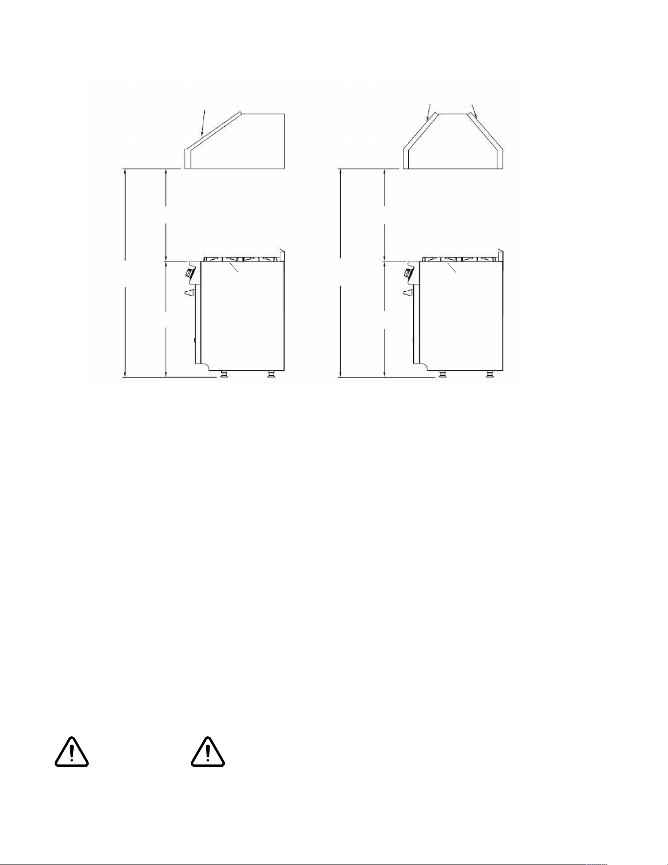
COOKTOP OPERATION
Push to release gas.
Heat Settings
Turn to Ignite and “Hi”
position.
36” Control Panel
Adjust to appropriate
flame height.
To light the surface burners, push and turn the appropriate control knob counter
clockwlse to a “Hi” position. You will hear a clicking noise
(the sound of the electric spark igniting the burner).
Once burner ignition has been achieved, turn the burner control knob to adjust the
flame size. If the knob stays at “Hi”, it will continue to click.
NOTE: When one burner is turned to the “Hi” position, all the burners will spark.
Do not attempt to disassemble or clean around any burner while another burner is on.
Do not touch any burner cap, burner base, or igniter while the igniters are sparking.
Hi
Ignites the burners.
Simmer
Melting small quantities, steaming
rice, warming food, melting chocolate
or butter.
Low
Melting large quantities.
Low - Medium
Low temperature frying, simmering
large quantities, heating milk, cream
sauces, gravies.
Medium
Sauteing and browning, braising,
pan-frying, maintaining slow boil on
large quantities.
Medium - Hi
High temperature frying, pan boiling,
maintaining slow boil on large
quantities .
Hi
Boiling liquid quickly, deep frying.
30
COOKTOP OPERATION
SIMMER AND BOIL
• A smaller flame will give the best simmer results. Small flames oer precise
cooking performance for delicate foods, keeping food warm, melting chocolate or
butter, and for cooking that need to cook over low heat for a long time.
• The highest (larger) flame settings provide the maximum heat that is available
on your range. This setting should be used for heavy cooking loads such as water
boiling and pasta cooking.
FLAME SIZE
• When you select the flame size, watch the flame when you turn the knob.
• Any flame larger than the bottom of the cookware is wasted.
• The flame should be steady and blue in color. Foreign material in the gas line may
cause an orange flame during initial operation.
POWER FAILURE
• If the gas does not ignite within four seconds, turn o the valve and allow at least
five minutes for any gas to dissipate. Repeat the lighting procedure.
• If the power fails, the surface burners can be lighted manually. Hold a lighted match
near a burner and turn knob counterclockwise to “HI”. After burner lights, turn
knob to setting.
COOKTOP
• To prevent the cooktop from discoloring or staining, clean cooktop after each use,
and wipe up acidic or sugary spills as soon as the cooktop has cooled.
• The sealed burners of your range are not secured to the cooktop and are designed
to be removed. Boil overs or spills will not seep underneath the cooktop. The
burners should be cleaned after each use.
Approximate 1” or 1.5”
Flame Height
31
COOKTOP OPERATION
FOOD SAFETY
According to the United States Department of Agriculture: DO NOT hold foods at
temperatures between 40°F to 140°F more than 2 hours. Cooking raw foods below
275°F is not recommended.
Never use this appliance as a space heater to heat or warm the room, Doing so many
result in carbon monoxide poisoning and overheating of the oven. Never use this
appliance as a storage space and storage cabinet areas.
Never use this appliance doors or drawers such as stepping.
Leaning or setting on the doors or drawers, may result in hazards and injuries
BURNER GRATES
a. The grates must be properly positioned before cooking (ref below 1.). Improper
installation of the grates may result in scratching of the cooktop and / or poor
combustion.
b. Do not operate the burners without a pan or utensil on the grates
(ref below 2.).
WARNING
WARNING
WARNING
1. 2.
32
HOW TO USE THE GAS OVEN
General features
The gas oven is provided with two burners:
The Oven burner, mounted on the lower part of the oven
The Broil burner, mounted on the upper part of the oven
Using the oven for the first time
It is advised to follow these instructions:
• Insert shelves and broiler grid and tray
• Turn the oven on to the maximum temperature position (500˚F) to eliminate
possible traces of grease from the oven burner. The same operation should be
followed for the Broil burner (knob on position BROIL).
• Unplug the power cord, let the oven cool down, then clean the interior of the oven
with cloth soaked in water and detergent (neutral) then dry carefully.
OVEN BURNER
Performs the normal “oven cooking” function.
• The gas flow to the burner is regulated by a thermostat which maintains the
desired oven temperature.
• The control of the temperature is determined by a thermostatic probe positioned
inside the oven.
• The probe must be always kept in its housing, in a clean condition, as an incorrect
position or a dirty probe may cause improper control of the temperature.
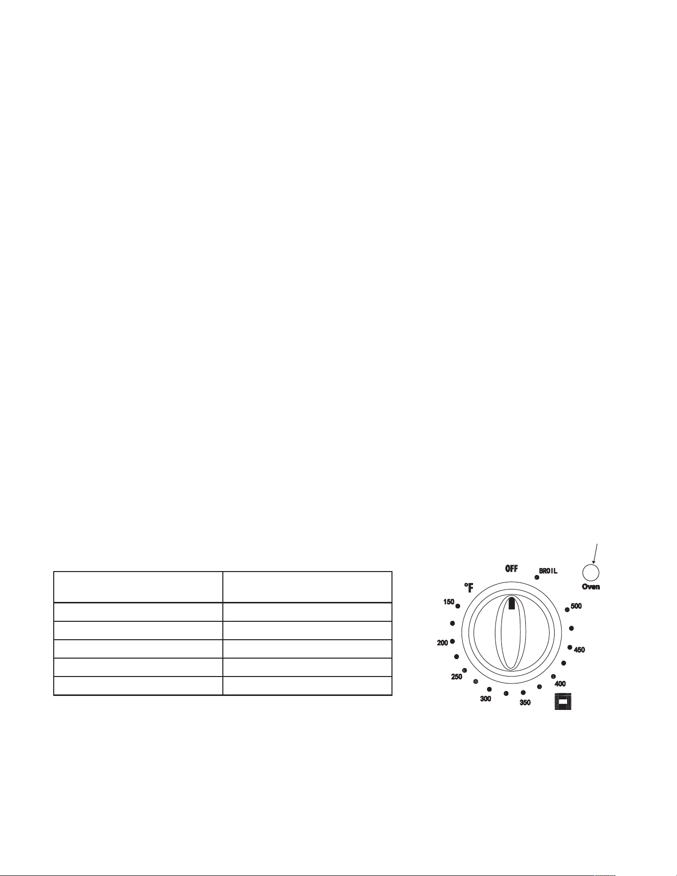
GAS OVEN SETTING
Number printed on the
knob (temperature in ˚F)
Corresponding
temperature in ˚C
150 66
350 177
400 204
450 232
500 260
OVEN INDICATOR LIGHT
The oven indicator light will remain on until the oven knob is turned to the
o position or the desired temperature is reached in the oven.
OVEN OPERATION
OVEN INDICATOR LIGHT
33
OVEN OPERATION
OVEN VENT
Do not block the ducts at the rear of the range when cooking in the oven. It is
important that the flow of hot air from the oven and fresh air into the oven burner
never be interrupted. Avoid touching the vent opening or nearby surfaces during oven
or broiler operation - they may become hot.
Never cover any slots, holes or passages in the oven bottom or cover an
entire rack with materials such as aluminum foil. Doing so blocks air flow through the
oven and may cause carbon monoxide poisoning. Aluminum foil lining may also trap
heat, causing a fire hazard. Do not use Aluminum Foil on any porcelain surface. Doing
so will cause damage the porcelain that aect the life of the porcelain.
OVEN FUNCTION
Natural Airflow Bake occurs when heat is transferred into the oven from the bake
burners in the bottom of the oven cavity. Heat is then circulated by natural airflow.
This is a traditional bake setting.
CONVECTION BAKE
Heat is transferred from the bake burners in the bottom of the oven cavity to the
oven cavity itself. The convection fan in the rear of the oven then circulates it. This
convection process provides more even heat distribution throughout the oven cavity.
Multiple rack use is possible for the large baking jobs. Convection cooking is faster,
can be accomplished at lower temperatures and provides more even temperatures
than regular cooking.
WARNING
34
OVEN OPERATION
OVEN THERMOSTAT
- The numbers printed on the control panel indicate the increasing oven temperature
value (°F).
- To regulate the temperature, set the chosen number onto the control knob indicator.
- The position BROIL serves only to turn on the broil burner.
Note: When the range will not be used for long periods of time, set the gas knobs
to their OFF positions and also close the gas shut-o valve placed on the main gas
supply line.
VERY IMPORTANT: The oven/broil shall be used always with the door closed.
CONVECTION ROAST
The convection fan circulates the heated air evenly over and around the food.
Using the cover and broiler pan provided, heated air will be circulated over the
around the food being roasted. The heated air seals in juices quickly for a moist and
tender product, while at the same time creating a rich golden brown exterior. When
convection roasting, it is important that you use the broiler pan for best convection
roasting results. The pan is used to catch grease spills and has a cover to prevent
grease splatters.
CONVECTION DEFROST
With temperature control o, the motorized fan in the rear of the oven circulates air.
The fan accelerates natural defrosting of the food without heat. To avoid illness and
food waste, do not allow defrost food to remain in the oven for more than two hours
without being cooked.
CONVECTION DEHYDRATE
With the temperature control on 175
O
F warm air is radiated from the bake burners
in the bottom of the oven cavity and is circulated by a motorized fan in the rear of
the oven. Over a period of time, the water is removed from the food by evaporation.
Removal of water inhibits growth of microorganisms and retards the activity of
enzymes.
BEFORE BAKING OR BROILING
The oven and broiler should be turned on to burn o the manufacturing oils. Turn
the oven on to 450°F (230 °C) for 20 to 30 minutes; then turn the oven knob to
“Broil” for the same length of time. You may wish to turn on the ventilator above
your range at this time.
WARNING
35
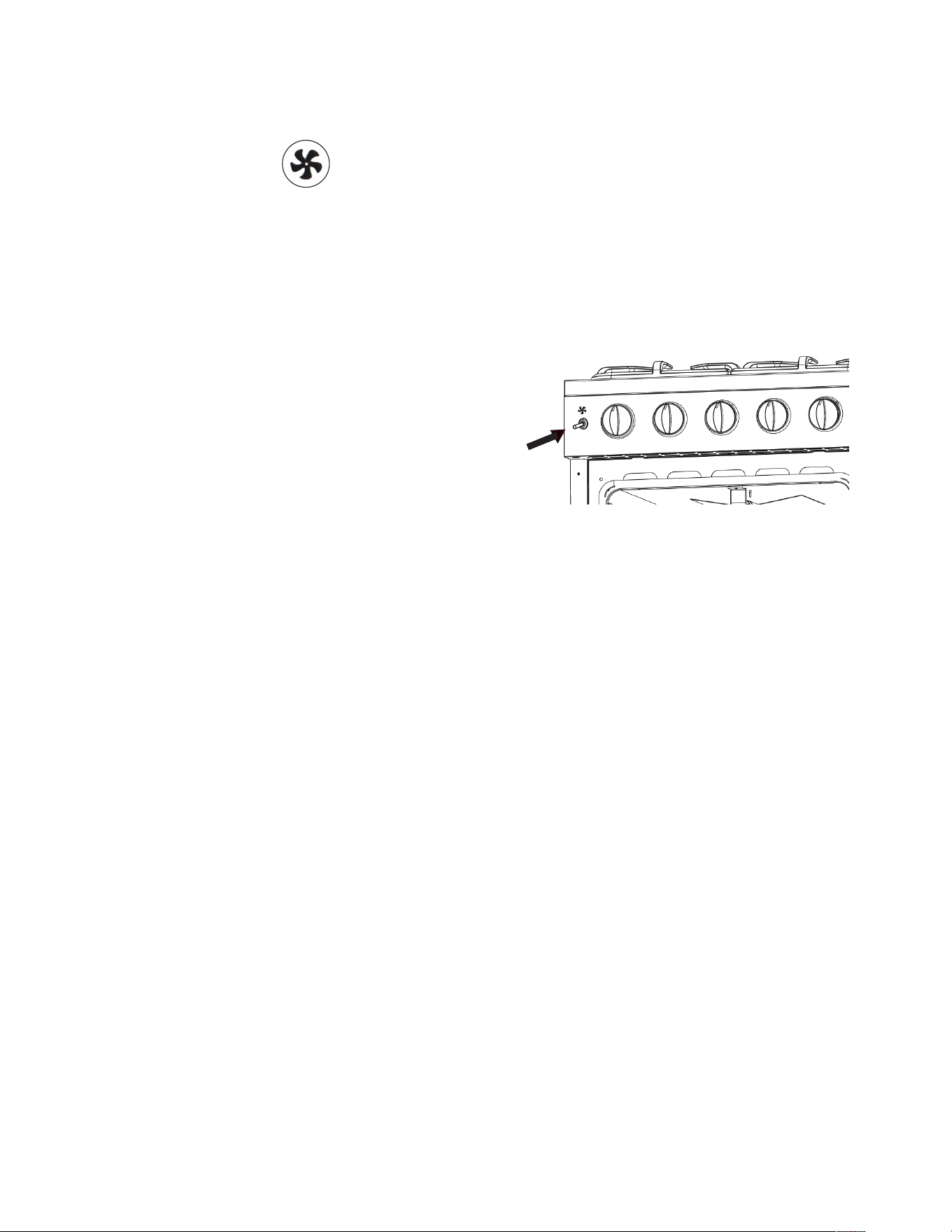
CONVECTION MODE
Heat is transferred from the bake burners in the bottom of the oven cavity to the
oven cavity itself. The convection fan in the rear of the oven then circulates the hot air,
providing even heat distribution throughout the oven. Convection cooking generally
provides a more even temperature with faster baking times than the standard oven
baking setting. This mode is controlled by a switch on the left hand side of the
control panel. Simply flick the switch on the left of the control panel to activate the
convection mode.
• Position the oven’s bottom cover and the oven shelf/shelves before using the oven.
Use more than one oven shelf for larger baking loads. Remove any unused shelves
and baking utensils from the oven.
• Preheat the oven to the temperature stated in the recipe before baking. Depending
on the temperature needed and the size of the oven, preheating will take 15 - 20
minutes. When the light goes o it has reached it’s desired temperature.
• Arrange pans and food items evenly on the shelves. Make sure pans do not touch
each other or the sides of the oven. When baking a single item, always center the
item on the oven shelf, preferably in the center of the oven. If baking on multiple
shelves, make sure to stagger items on the shelves so that one is never directly
above another.
CONVECTION ROASTING
When convection roasting, it is important that you use a broiler pan for best convection
roasting results. A broil/roast pan (with a rack) elevates the roast to allow the hot air
to circulate around the meat, sealing in juices for a moist and tender roast with a richly
browned exterior (similar to a rotisserie eect.) The pan is also used to catch any
drippings from the roast, keeping the oven clean and reducing the chance of smoking
or flare-ups. The convection fan circulates heated air evenly over and around the food,
sealing in juices for a moist and tender roast with a richly browned exterior.
CONVECTION DEFROST
With the temperature control o, a motorized fan in the rear of the oven circulates
air. The fan accelerates natural defrosting of the food without heat. To avoid bacteria
growth, food-borne illness and food waste, do not allow defrosted food to remain in the
oven for more than 2 hours without being cooked.
OVEN OPERATION
Convection Mode Switch
36
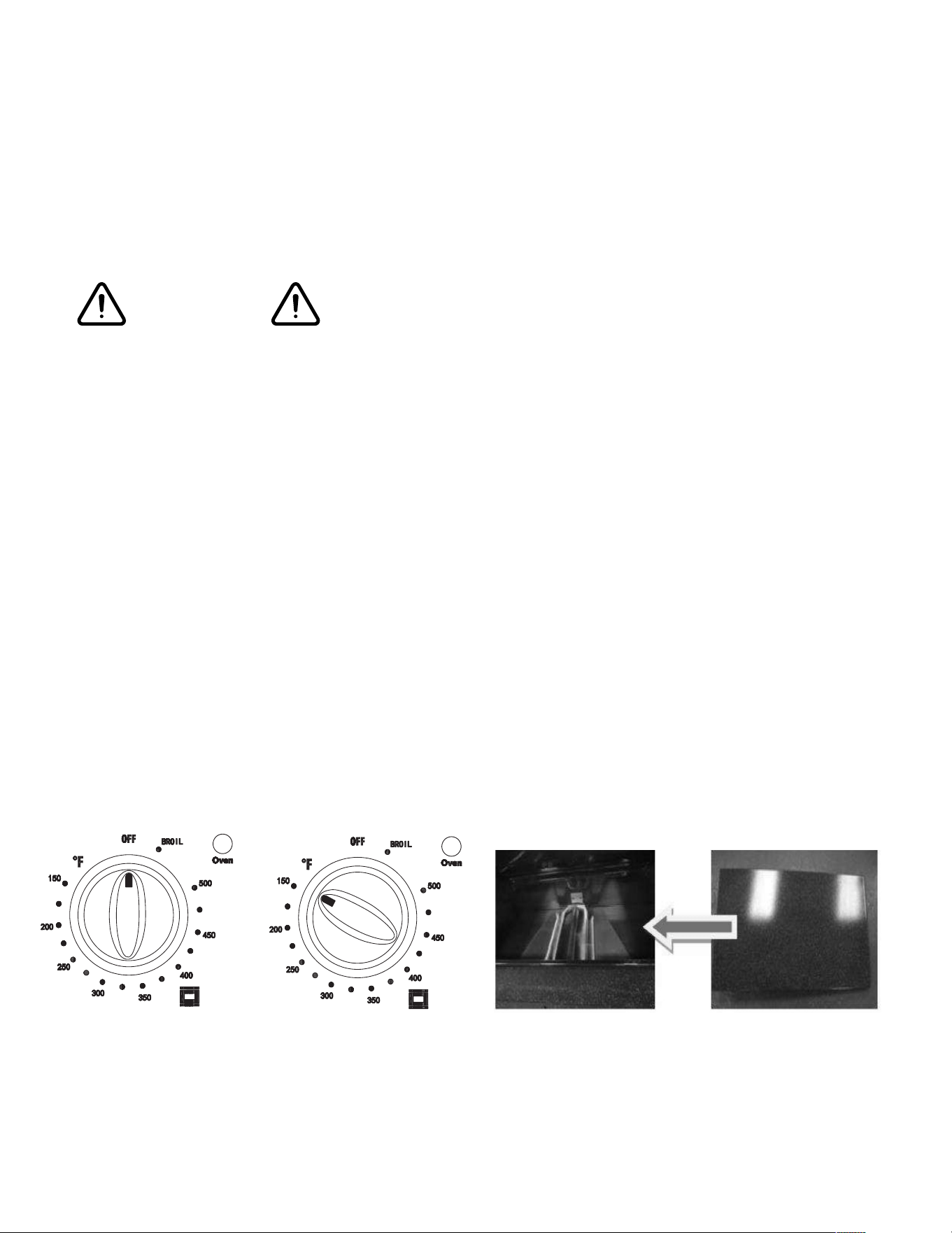
OVEN OPERATION
1. When using the range for the first time or after long period of non-usage, keep
pressing the knob inward for approximately 10 – 15 seconds after the burner has lit to
ensure the gas valve has been accurately primed.
2. Slowly close the oven door. If the flame extinguishes for any reason, the safety valve
will automatically shut o the gas supply to the burner.
To re-light the burner, first turn the oven control knob to the position, wait for at
least 1 minute and then repeat the lighting procedure.
Always broil with oven door closed. Attention: the oven door becomes very hot
during operation. Keep children away.
BROILING
Very important: the broil burner must always be used with the oven door closed.
Position the oven rack on the second level from the top
1. Turn on the broil burner, as explained in the preceding paragraphs and let the broil
burner preheat for about 5 minutes with the door closed.
2. Place the food to be cooked below the broiler.
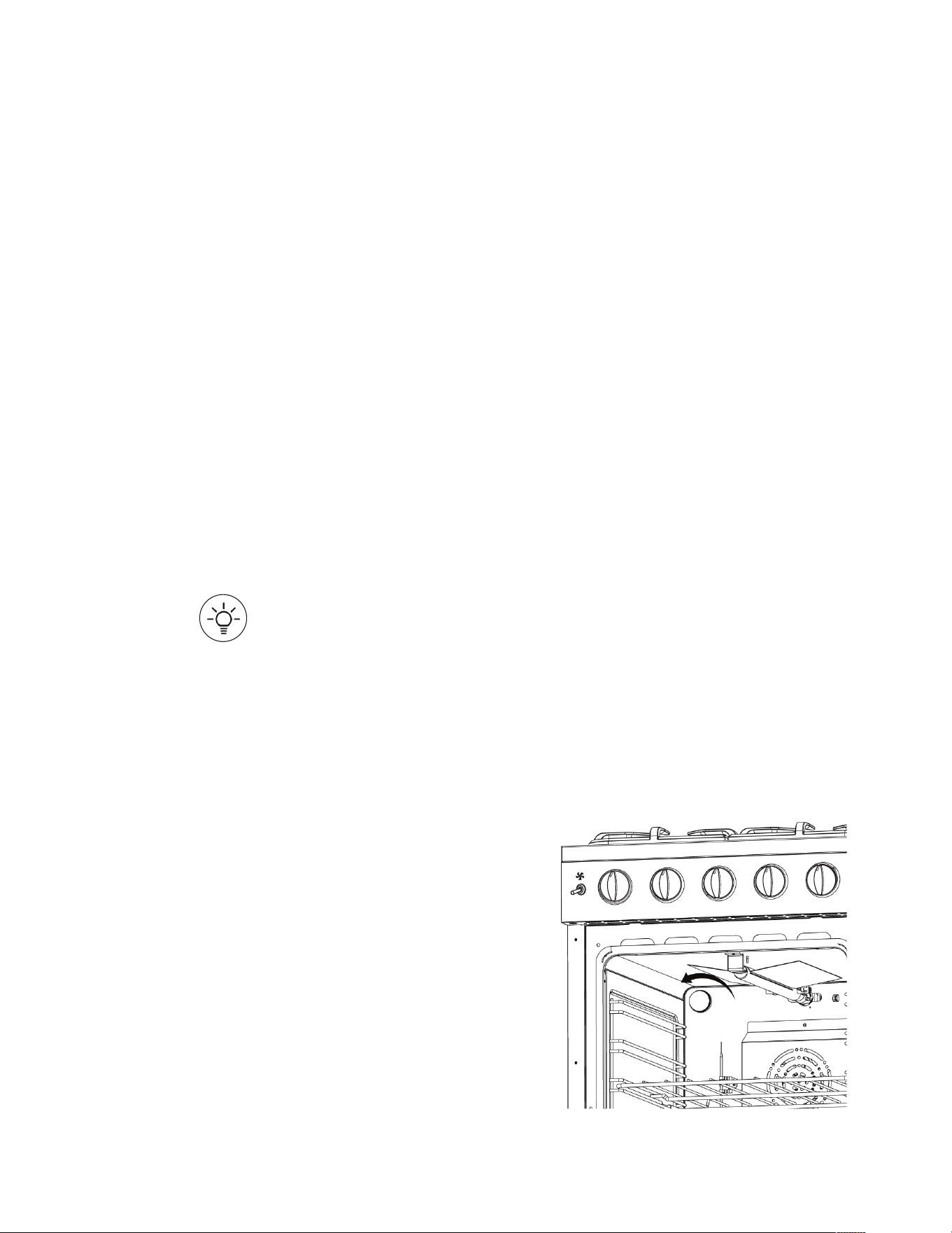
OVEN LIGHT
The range is equipped with two lights that illuminate the oven to enable visually
controlling the food that is cooking. The lights are controlled by a switch on the right
hand side of the control panel.
CHANGING OVEN LIGHT BULB
Remove light bulb cover and unscrew light bulb counter clockwise.
Replace with an E14 120V 25W 300°C bulb.

37
BROILER OPERATION
NOTE: Door must be closed during broiling operation.
Broiling is a method of cooking tender cuts of meat directly under the infrared broiler
in the oven. Broiling in the oven is accomplished with the oven door closed. It is
normal and necessary for some smoke to be present to give the food a broiled flavor.
TO BROIL
Broil one side until the food is browned; turn and cook on the second side. Season
and serve. Always pull the rack out to the “stop” position before turning or removing
food.
SETTING BROIL
The “Oven” selector knob controls the Broil feature. When broiling, heat radiates
downward from the oven broiler for even coverage. The Broil feature temperature is
500°F (260°C).
A broil pan and insert used together allow dripping grease to drain and be kept away
from the high heat of the oven broiler. DO NOT use a broil pan without the insert.
DO NOT cover the broil pan insert with foil. The exposed grease could catch fire.
To set the oven to Broil:
1. Place a broiler pan insert on the broiler pan. Then place the food on the broiler pan
insert
2. Arrange the interior oven rack and place a broiler pan on rack. Be sure to center
the broiler pan and position directly under the broil burner. If preheating the broil
burner first, position the broiler pan after the broil burner is preheated.
3. Turn selector knob to Broil. The oven indicator light will remain on until the selector
knob is turned to the o position or the temperature control cycles o.
38
Grates, Main Tops, Surface Burners
The grates are made of cast iron. These materials can be cleaned at the sink with
detergent or soap-filled scouring pads. Do not be alarmed when the grate loses its shiny
finish. The heat from the burners will cause the grates to lose their shiny finish.
Clean the burner with soap and water, rinse thoroughly and dry completely before
reassembling. Burner heads can be dried in the oven at about 350 degrees Fahrenheit
or in the dishwasher on the dry cycle. After adjustment or cleaning, replace all parts to
their original position.
Stainless Steel Elements
The stainless steel parts can be cleaned with detergent and warm water.
Stainless steel parts must be rinsed with water and dried with a soft and clean cloth or
with a chamois leather.
For dicult grime, use a commercially available, non-abrasive product for cleaning
stainless steel surfaces, or a little hot vinegar.
Note: Regular use could cause discoloring around the burners, because of the high
flame temperature.
Products of combustion from the top pilots as well as certain atmospheric conditions
can create an oxidation reaction on the underside of the top. This will appear as rust or
in the form of a reddish brown deposit. This will NOT AFFECT THE LIFE OF THE TOP in
comparison to the general life expectancy of the range itself.
It is very important that the burner be dry before replacing it in the range. A wet burner
will not allow the gas to ignite properly. This could result in a build-up of gas which
could result in an explosion or fire.
Aluminum Foil in Oven
NEVER cover any slots, holes or passages in the oven bottom or cover an entire rack
with materials such as aluminum foil. Doing so blocks air flow through the oven and
may cause carbon monoxide poisoning. Aluminum foil linings may also trap heat,
causing a fire hazard.
Aluminium foil when used improperly is a cause of many range fires. Make certain that
vents or air openings aren’t covered by the foil. If the vents located along the sides of
the oven bottom are blocked, poor cooking will result.
Never cover a rack completely. A piece of foil slightly larger than the cookware can be
placed on the rack beneath the cookware.
Remove and discard aluminum foil after each use. This will help prevent grease and
spilled food from accumulating and becoming a fire hazard.
CARE AND MAINTENANCE
WARNING

39
Cleaners and Cleaning Materials
Do not use harsh cleaners or degreasers on or around functional parts (valves, controls,
etc., or aluminum tubing). This will damage or drastically reduce the life of the part.
Use only a mild solution of soap and water on backguards, aluminum control panels
and painted surfaces. Never use harsh abrasives or cleaning powders that may scratch
or mar the surface. Make sure the cleaners and cleaning materials are suitable for use
on the area to be cleaned. Always keep cleaning materials in a safe place. Never use a
sharp metal scraper to clean glass, porcelain, or painted surfaces.
Repair Parts
When repair parts are needed, contact the dealer from whom the range was purchased.
In case your range was purchased from a source other than an appliance dealer, you
may prefer to contact the manufacturer at the address shown in this manual.
Moisture
During the initial heat-up of your range, the heat mixing with the cooler air in the oven
cavity may produce fogging of the door glass or a collection of water on the door.
To prevent this, open the oven door for the first few seconds of initial oven heat-up.
This will allow the moist air within the oven to escape, without the forming of visible
moisture on the range. The amount of moisture will depend upon the humidity of the
air and water content of the food being cooked. Fogging and even dripping water will
usually occur in geographic locations of high humidity.
BURNERS AND CAST-IRON GRIDS
• These parts can be removed and cleaned with appropriate products.
• After cleaning, the burners and their flame distributors must be well dried and
correctly replaced.
• It is very important to check that the burner flame distributor and the cap has been
correctly positioned - failure to do so can cause serious problems.
• In appliances with electric ignition keep the electrode clean so that the sparks always
strike.
Note: To avoid damage to the electric ignition do not use it when the burners are
not in place.
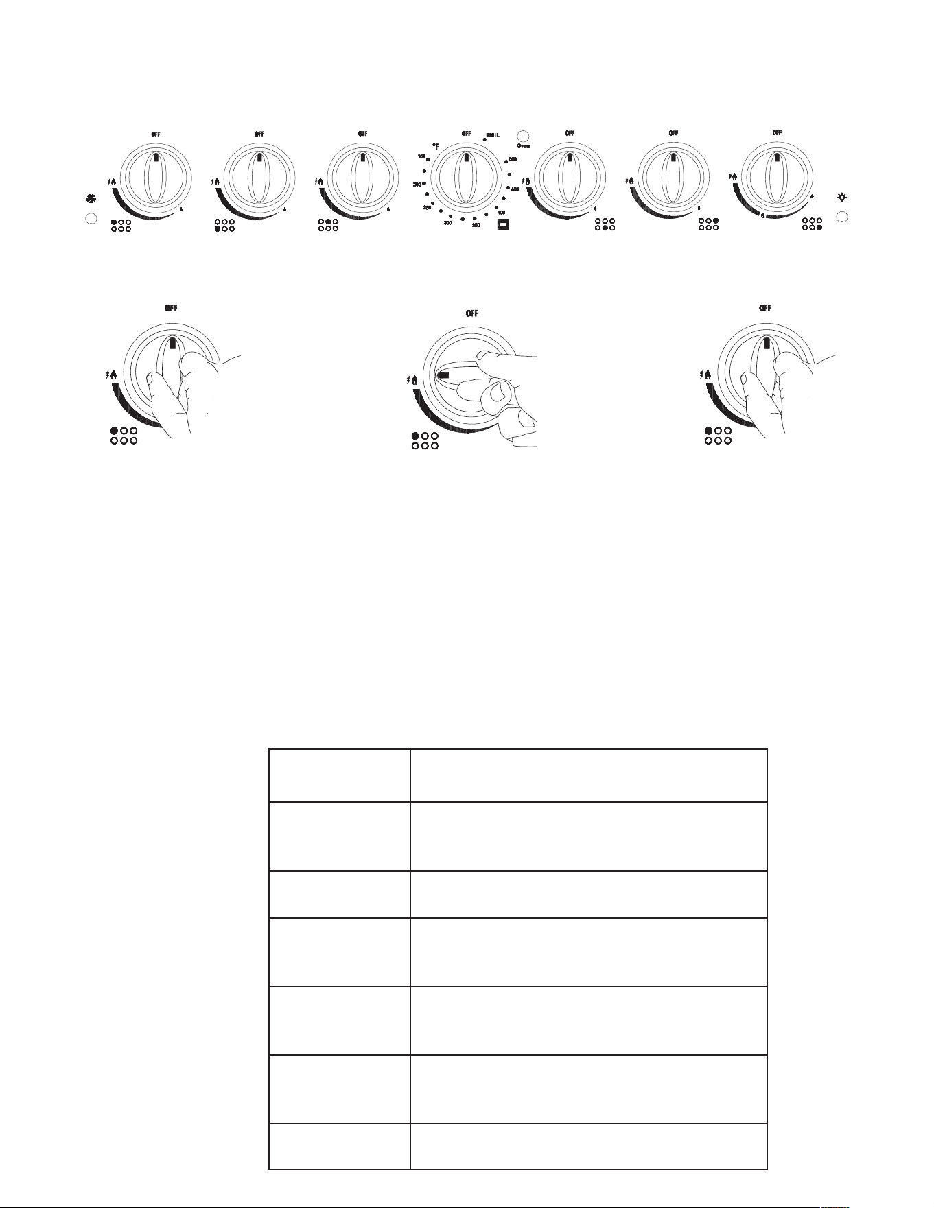
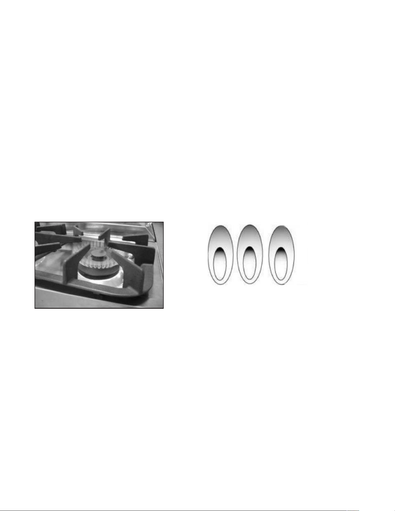
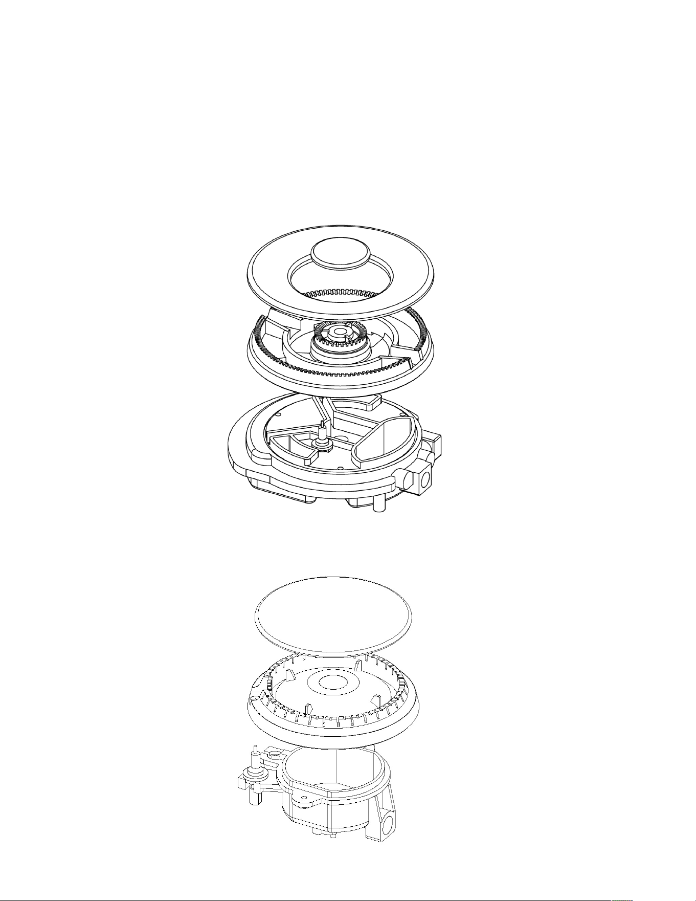
CORRECT REPLACEMENT OF THE BURNERS
It is very important to check that the burner
flame spreader and the cap have been
correctly positioned. Failure to do so can cause
serious problems. In appliances with electric ignition,
check that the electrode is always clean to
ensure trouble-free sparking.
The ignition plug must be cleaned very carefully.
CARE AND MAINTENANCE
40
CARE AND MAINTENANCE
20000 BTU Triple Crown
Burner
2000/15000 BTU Burner
CORRECT REPLACEMENT OF THE BURNERS
It is very important to check that the burner flame spreader and the cap have been
correctly positioned. Failure to do so can cause serious problems. In appliances with
electric ignition, check that the electrode is always clean to ensure
trouble-free sparking.
The ignition plug must be cleaned very carefully.
41
OVEN RACK INSTALLATION AND REMOVAL
• The oven racks are provided with a safety catch to prevent accidental removal.
• They must be inserted as shown.
• To pull them out remove the rack in the reverse order.
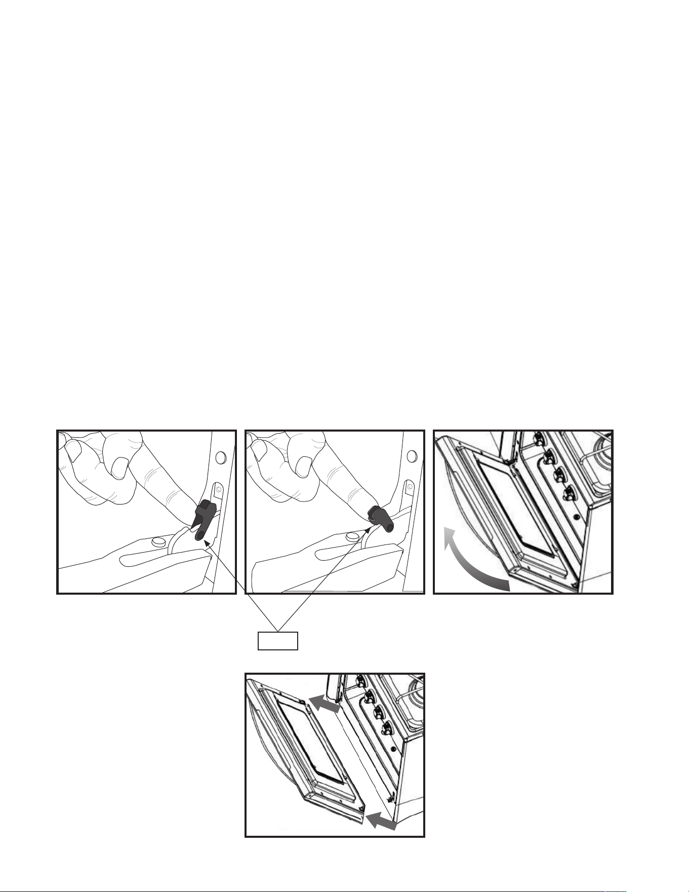
REMOVING THE OVEN DOOR FOR CLEANING
To facilitate oven cleaning, it is possible to remove the door. Please follow
the instructions carefully:
The oven door can easily be removed as follows:
• Open the door to fully.
• Lift the left and right hooks on the hinge figure (A, B).
• Hold the door as shown in figure (C) on a 45 degree angle.
• Gently close the door until the hooks touch the door, then lift at a 45 degree angle (D)
• Set the door on a soft flat surface.
• To replace the door, repeat the above steps in reverse order.
(C)
(D)
(B)(A)
HOOK
CARE AND MAINTENANCE
42
CARE AND MAINTENANCE
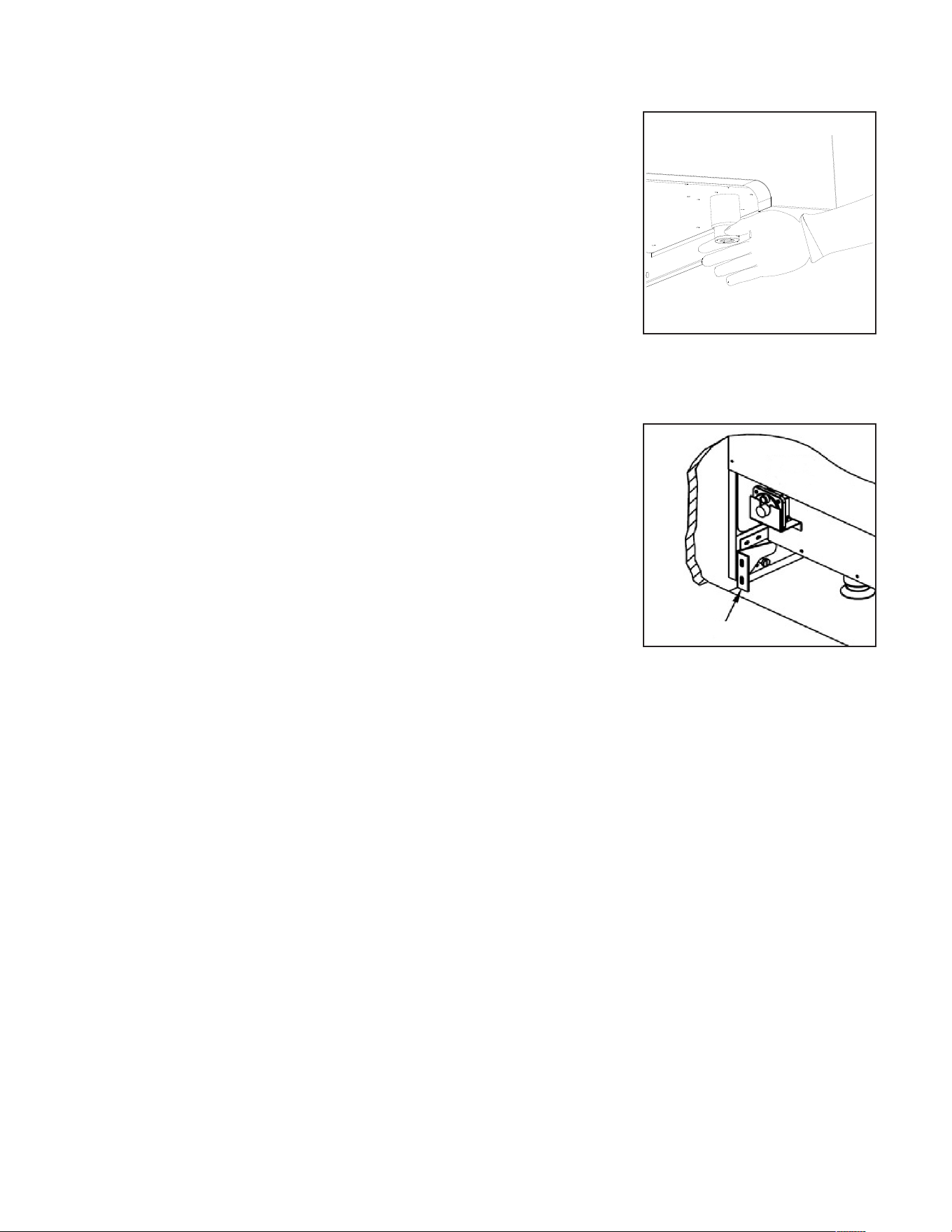
LEVELING THE RANGE
The range must be level to obtain proper operating.
The four screws type leveling legs located on the
corners at the bottom of range should be adjusted
by turning them clockwise to make the range higher
or counter-clockwise to lower the range until the
range is level. Use a level on surface units to
check the leveling of the range.
ANTI-TIP BRACKET INSTALLATION
To reduce the risk of tipping the range by abnormal
usage or improper door loading, the range must
be secured by properly installing the anti-tip device
packed with the appliance.
• Place the anti-tip bracket on the floor as
shown figure. Anti-tip bracket can be installed
on the right and left side.
• Make the locations of 2 (x2) holes of
ant-tip bracket on the floor.
• Use a drill bit
• Secure bracket to floor using screws supplied.
• Slide appliance into position.
Note: If range is relocated, the bracket must be removed and installed in new location.
Anti-tip Bracket

43
CARE AND MAINTENANCE
COOKTOP
• To avoid electrical shock or burns, turn o all controls and ensure the cooktop is
cool before cleaning.
• Before cleaning the cooktop, ensure that all burners are turned o and that all
components are cool enough to safely touch.
• Do not use harsh or abrasive cleaning agents, waxes, polishes, or commercial
cooktop cleaners to clean the cooktop.
• Use only a sponge, soft cloth, fibrous or plastic brush, and nylon pad for cleaning.
• Always dry components completely before using the cooktop.
CONTROL PANEL, DOOR HANDLE, CONTROL HOUSING
• Clean the control panel, door handle and control housing with a solution of mild
detergent and warm water.
• Do not use abrasive cleaners or scrubbers; they will permanently damage the
finish.
• Dry the components with a soft, lint-free cloth.
OVEN WINDOW
• Clean all glass surfaces with a solution of mild detergent and hot water. Use a mild
glass cleaner to remove fingerprint or smears.
• Dry completely with a soft, lint-free cloth.
PORCELAIN SURFACES
• Clean oven interior and inner door liners with a solution of mild detergent and hot
water. Rinse and dry with a soft cloth. Do not use abrasives or commercial oven
cleaners.
PORCELAIN SURFACES
• Do not use any cleaning product containing chlorine bleach.
• Do not use a steel-wool pad; it will scratch the surface.
• Use a hot, damp cloth with a mild detergent. Use a clean, hot, damp cloth to
remove soap. Dry with a dry, clean cloth.

44
CARE AND MAINTENANCE
METAL FINISHES
• Wash with soap and water, glass cleaner, or mild liquid sprays.
OVEN RACKS
• Clean oven racks with solution of detergent and hot water. To clean heavy soil, use
a scouring pad such as steel wool with plenty of water.
OVEN FRAME
• Clean with hot water, soap-filled steel-wool pads or cleaners.
Rinse well with clean water and dry.
OVEN GASKET
• Do not clean the gasket. The fiberglass material of the oven door gasket cannot
withstand abrasion.
• It is necessary for the gasket to remain intact.
OUTER OVEN DOOR
• Use soap and water to thoroughly clean the top, sides and front of the oven door.
Rinse well. You may also use a glass cleaner to clean the glass on the outside of the
door.
• Do not use oven cleaners, cleansing powders of harsh abrasives on the outside of
the door.
INNER OVEN DOOR
• Do not allow excess water to run into any holes or slots in the door. Any soap left
on the liner causes additional stains when the oven is heated.
• Before you call for service, please review the potential problem / possible causes
and remedies shown in the table below.
45
TROUBLESHOOTING
Nothing works
• Oven is not connected to the
electrical power.
• Power supply is not energized.
• Have oven connected to a properly sized
electrical power supply by a qualified
electrician.
• Have an electrician check the power
supply, including the house circuit
breaker, wiring and fuses
Top burners do not
light or do not burn
evenly.
• Plug on range is not completely
inserted in the electrical outlet.
• Burner holes on the side of the
burner may be clogged.
• Make sure the unit is properly connected
to the power supply
• Remove the burner heads and clean
them. Check the electrode area for
burned-on food or grease.
Burner flames very
large and yellow.
• Burner bezel ports are clogged.
• Burner ports or burner caps are
not positioned properly.
• Cooktop is being operated with
the wrong type of gas.
• Regulator is not installed, is faulty,
or is set for the wrong type of gas.
• Clean burner bezel ring ports with
straightened paper clip, needle, or wire.
• Remove and carefully re-install burner
bezel and caps.
• Ensure that the type of cooktop matches
the natural gas supply.
• Check installation, replace regulator, or
set regulator for proper gas.
Sparking but no
flame ignition.
• Gas shut-off valve is in the
’OFF’ position.
• Turn shut-off valve to the ‘ ON’ position.
lgniters spark
continuously after
flame ignition.
• Power supply polarity is reversed.
• Igniters are wet or dirty.
• Have polarity corrected.
• Dry or clean igniters.
Burner flame goes
out at low setting.
• Low gas supply pressure.
• Air intake holes around knobs are
obstructed.
• Contact gas company.
• Remove obstruction.
Oven will not heat
• Oven settings are not corrected
• Follow mode selection and clock settings
as specified in Oven Operation section of
the manual.
Foods over-cooked
or under-cooked
• Incorrect cooking time or
temperature.
• Adjust time, temperature, or rack
position.
‘Cracking’or
‘Popping’sound.
• This is the sound of metal
heating and cooling.
• This is normal.
The flames have
suddenly gone out
• A draft or spill has extinguished
the flame.
• No action required. The burner will
detect this and automatically re-light.
However if there has been a large spill,
we recommend turning the burners off
and cleaning the burners and sump area.
See “Care and Cleaning” for instructions.
Before you call for service, please review the potential
problems and possible causes and remedies shown in the table.
Problem Possible Cause Remedy
46
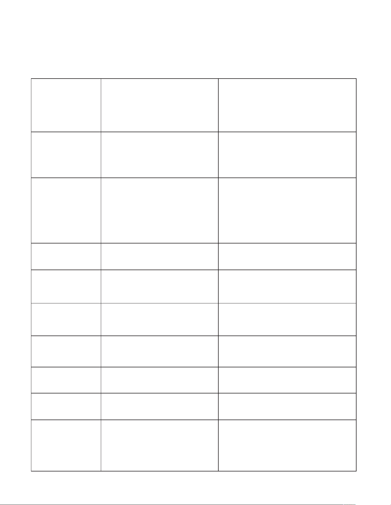
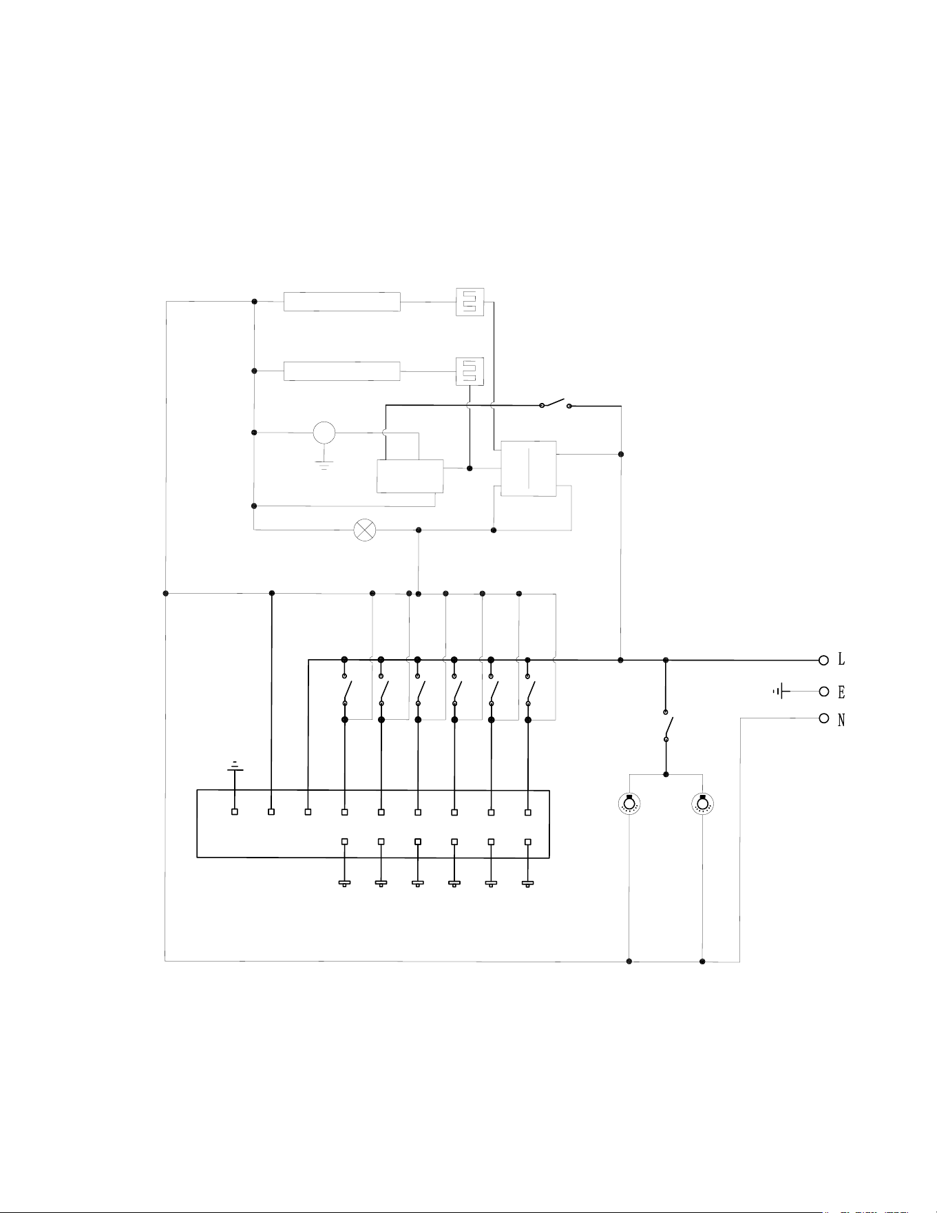
WIRING DIAGRAM
Oven Light
Switch
Oven Light
Left
2
1
C
BR
BA
Thermostat
Oven Indicator Light
13
9
5
1
14
12
8
4
Relay
Broiler Safety Valve
Broil Ignitor
Fan Switch
M
Fan
Bake Safety Valve
Burner Ignitor
E N A
SW6 SW5 SW4 SW3 SW1
S6 S5 S4 S3 S1
Pulse
ignition
SW2
S2
Microswitch
36" Wire Diagram
detatch along dotted line detatch along dotted line
47
APPLIANCE INFORMATION
(manual copy - keep with your records)
APPLIANCE INFORMATION
(remote copy - keep with your appliance)
detatch along dotted line detatch along dotted line
To make care and servicing of your range easy and ecient, please record the
following information for future reference:
Model:
Serial Number:
Purchased From:
Date Purchased:
Installed By:
To make care and servicing of your range easy and ecient, please record the
following information for future reference:
Model:
Serial Number:
Purchased From:
Date Purchased:
Installed By:

48
CLASSIC RETRO BY UNIQUE 36” TRIPLE CROWN
CONVECTION GAS RANGE
Unique Appliances Ltd. (hereafter “Unique”) warrants that this UNIQUE gas range is free from manufacturer’s
defects in material and workmanship under normal usage and service under the following terms.
Parts Warranty
This appliance has been designed for domestic household use. If properly installed, adjusted and operated under normal
conditions in accordance with printed instructions, it will satisfactorily perform the functions that are generally expected of this
type of appliance.
If the appliance fails to do so because of a defect in material or workmanship within one year from the original date of purchase:
Unique will at our option, repair, exchange, or correct by other means Unique consider appropriate, any part(s) Unique finds to
be defective except for the surface finish.
Ownership
This Warranty is made only to the first purchaser (”original purchaser”) who acquires this range for his/her own use and will be
honored by Unique Appliances and by the Seller. Purchaser must retain their receipt as proof of purchase date.
Warranty Conditions
This warranty does not apply to any appliance that has been subjected to alterations, misuse, abuse (including damage by
foreign agents or chemicals), accident, improper installation or service, delivery damage, or other than normal household use
and service. This UNIQUE appliance must be serviced regularly as outlined in the Owner’s Manual. In case of damage, the owner
must provide proof of purchase, Model, and Serial Number to the selling dealer or Unique Appliances. This warranty is LIMITED
STRICTLY to the terms indicated herein, and no other expressed warranties or remedies thereunder shall be binding on Unique.
Purchaser’s Responsibilities
The purchaser will be responsible for the costs of any service calls requested to demonstrate or confirm the proper operation
of the appliance, the installation, or to correct malfunctions in the appearance created by the operation of the appliance in a
manner not prescribed by or cautioned against in the use and care instructions.
Model and Serial Number
The appliance model number and serial number can be found on a rating plate located on the range. The purchaser should
always refer to the model and serial number when talking to or contacting the dealer from whom the appliance was purchased.
EXCLUSIONS
Save as herein provided, by Unique, there are no other warranties, conditions, representations or guarantees, express or implied,
made or intended by Unique or its authorized distributors and all other warranties, conditions, representations or guarantees,
including any warranties, conditions, representations or guarantees under any Sale of Goods Act or like legislation or statute is
hereby expressly excluded. Save as herein provided, Unique shall not be responsible for any damages to persons or property,
including the unit itself, howsoever caused or any consequential damages arising from the malfunction of the unit and by the
purchase of the unit, the purchaser does hereby agree to indemnify and hold harmless Unique from any claim for damages to
persons or property caused by the unit
Removal or disfigurement of the rating plate will void the warranty. The purchaser will be responsible for any expenses involved
in making the gas range readily accessible for servicing. The purchaser will be responsible for any extra charges where the
installation is in a remote location such as un-assumed roads, islands, areas known as cottage country, more than 20 Km outside
a Metropolitan area, or where a technician is not available. Freight damage is not covered by this warranty.
GENERAL PROVISIONS
No warranty or insurance herein contained or set out shall apply when damage or repair is caused by any of the following:
1) Power failure.
2) Damage in transit or when moving the appliance.
3) Improper power supply such as low voltage, defective house wiring or inadequate fuses.
4) Accident, alteration, abuse or misuse of the appliance such as inadequate air circulation in the room or abnormal operating
conditions (ie. extremely high or low room temperature).
5) Use for commercial or industrial purposes (ie. If the appliance is not installed in a domestic residence).
6) Fire, water damage, theft, war, riot, hostility, acts of God such as hurricanes, floods etc.
7) Service calls resulting in customer education.
8) Improper Installation (ie. Building-in of a free standing appliance or using an appliance outdoors that is not approved for
outdoor application, including but not limited to: garages, patios, porches or anywhere that is not properly insulated or
climate controlled).
Proof of purchase date will be required for warranty claims; retain bills of sale. In the event that warranty service is required,
present the proof of purchase to our authorized service depot.
Nothing within this warranty shall imply that Unique will be responsible or liable for any direct or indirect loss of foods
caused by failure in operation.
Factory Assistance
If the purchaser is unable to locate an authorized dealer/service agent, or if the purchaser does not receive satisfaction from the
dealer, they may contact Unique Appliances Customer Service directly at Toll Free 1-877-427-2266 or 905-827- 6154.
49
NOTES
Toll-free
1-877-427-2266 or 1-905-827-6154
available during regular business hours,
8:30 am to 4:30 pm, EST
Website
www.UniqueAppliances.com
Email
info@UniqueAppliances.com
CONTACT US
For general information or questions related to the operation, safety or the
purchase of your range, please contact our customer service department:
PRODUCT REGISTRATION
Please visit our website at https://UniqueAppliances.com/product-registration/ to
register your product.
Please visit our website for more quality Unique products:
www.UniqueAppliances.com
Unique Appliances Ltd., 2245 Wyecroft Road #5,
Oakville, Ontario, Canada, L6L 5L7
50
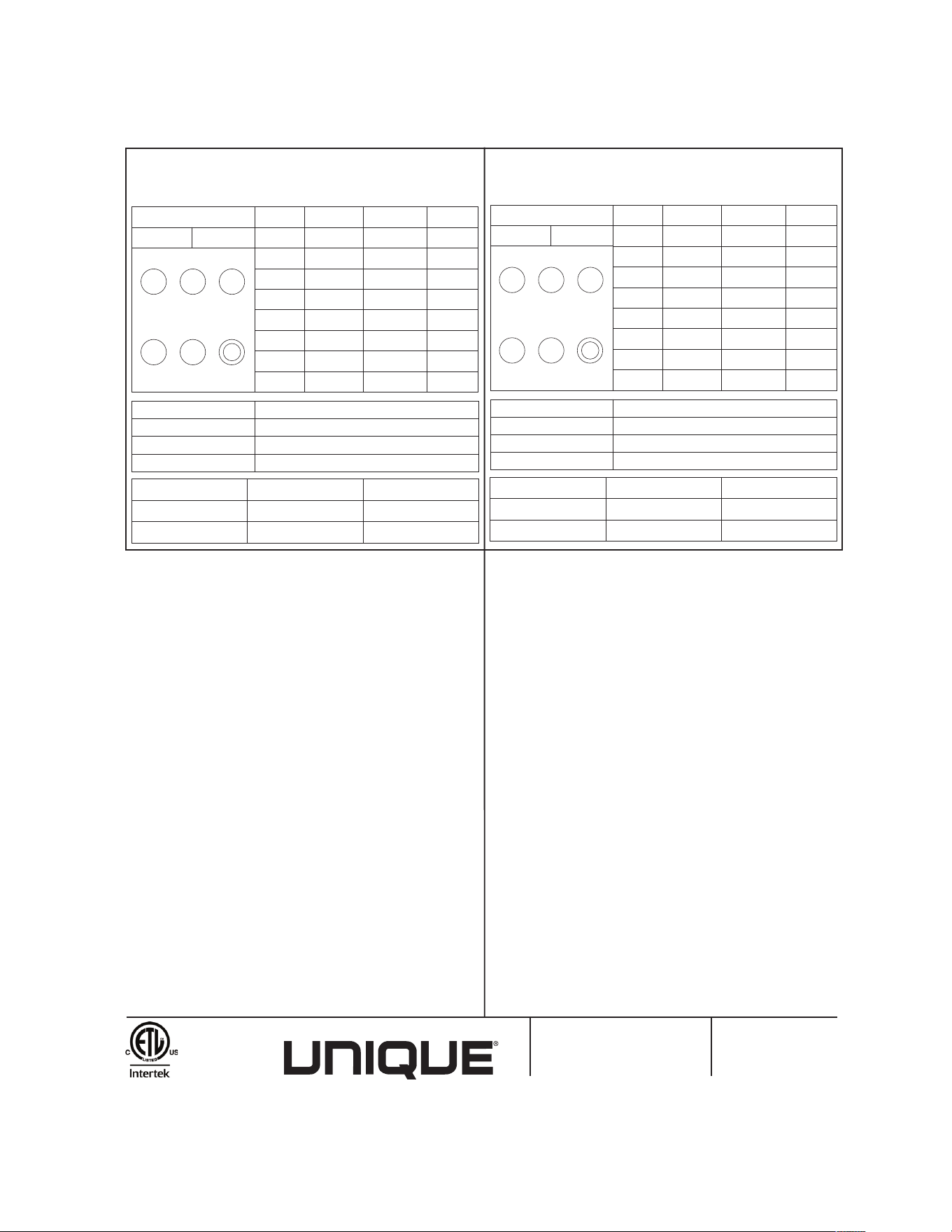
RATING PLATE
Conforms to ANS1 STD Z21.1-2018 Certified to CSA STD 1.1-2018
HOUSEHOLD COOKING APPLIANCE. FOR INDOOR USE ONLY.
Model: UGP-36CR Serial No:
En conformité avec ANS1 STD Z21.1b-2018 Certifiés CSA STD 1.1-2018
APPAREIL DE CUISSON DOMESTIQUE. POUR USAGE INTÉRIEUR SEULEMENT.
Modèle: UGP-36CR N
o
de série:
Email / courriel:
Uniqueappliances.com
2245 Wyecroft Road, Oakville, ON
Canada L6L 5L7
Toll-free / sans frais: 877-427-2266
Manufactured & certified by: / Fabriqué et certifié par:
File Number:
4002621
Burner NG LPG (BTU/H)
A 1.36*2+0.73 0.89*2+0.53 20000
B 1.57 1.0 12000
C 1.07 0.74 6000
D 1.36 0.9 9000
E 1.79 1.16 15000
F 1.36 0.9 9000
Broil 1.42 0.94 10000
Oven 2.13 1.4 22000
Type of Gas
Natural Gas LP Gas
F D B
E C
A
INPUT PRESSURE
OVEN
OVEN LIGHT
IGNITOR
OVEN FAN
NG 7inch
120V, 60HZ, 5.0 AMP
Top Burners Brûleurs Supérieurs
Triple Crown
Burner
Brûleur Triple
Couronne
120V, 60HZ, 0.2 AMP
120V, 60HZ, 3 AMP
120V, 60HZ, 0.53 AMP
5inch
LPG 11inch 10inch
OUTPUT PRESSURE
Brûleur GN GLP (BTU/H)
A 1.36*2+0.73 0.89*2+0.53 20000
B 1.57 1.0 12000
C 1.07 0.74 6000
D 1.36 0.9 9000
E 1.79 1.16 15000
F 1.36 0.9 9000
Griller 1.42 0.94 10000
Four 2.13 1.4 22000
Type de Gaz
Gaz Naturel GPL
F D B
E C
A
PRESSION D’ENTRÉE
FOUR
LUMIÈRE DU FOUR
ALLUMEUR
VENTILATEUR DU FOUR
GN 7po
120V, 60HZ, 5.0 AMP
120V, 60HZ, 0.2 AMP
120V, 60HZ, 3 AMP
120V, 60HZ, 0.53 AMP
5po
GPL 11po 10po
PRESSION DE SORTIE
Minimum distance from the sides of the range above the countertop to
flammable walls be at least 13 inches. The minimum horizontal distance is
18 inches between the appliance and flammable structure extending from
the cooking surface. The minimum vertical clearance between the
countertop surface and flammable structure above the appliance is 30
inches. The minimum horizontal distance between overhead cabinets
installed on either side of the appliance shall not be less than the nominal
width of the appliance. A floor supported unit requires no space between
adjacent flammable structures. Do not store or use a gasoline liquid
propane cylinder or other flammable vapours and liquids in the vicinity of
this appliance. The gas appliance pressure regulator must be set for the gas
with which the appliance is used with Natural gas. Only the gas for which
the appliance is shipped from the factory adjusted for use with Natural Gas.
You can find the orifices in the package with LP manual. Conversion orifices
are located in the LP package. Please follow the instructions in the package
with the gas conversion orifices. Each orifice shall be clearly identified for
the gas for which it is designed, and the orifice size shall be indicated on
the spud. Vented unit. See installation instructions. May be vented. If
vented, see installation instructions. The gas appliance pressure regulator
must be set for the gas with which the appliance is used.
La distance minimale à respecter à partir des côtés de la cuisinière
audessus du comptoir jusqu’aux parois latérales inflammables doit être
d’au moins 13 po (33cm). La distance horizontale minimale entre l’appareil
et la structure inflammable s’étendant depuis la surface de cuisson est de
18 po (45cm). Le dégagement vertical minimal entre la surface du comptoir
et la structure inflammable au-dessus de l’appareil est de 30po (76 cm).
La distance horizontale minimale entre les armoires supérieures installées
de chaque côté de l’appareil ne doit pas être inférieure à la largeur
nominale de l’appareil. Une unité posée sur le sol ne nécessite aucun
aspace entre les structures inflammables adjacentes. Ne pas entreposer ni
utiliser d’essence, de bonbonne de propane liquide ni d’autres liquides ou
vapeurs inflammables à proximité de cet appareil. Le régulateur de
pression du gaz de l’appareil doit être réglé selon le type de combustible
utilisé par l’appareil avec du gaz naturel. Seul le type de gaz utilisé par
l’appareil est identifié. L’appareil est réglé pour une utilisation avec du gaz
naturel lorsqu’il quitte l’usine. Les orifices se trouvent dans l’emballage
avec le guide de gaz liquide. Les orifices de conversion se situent dans
l’emballage de gaz liquide. Veuillez suivre les instructions fournies avec les
orifices de conversion de gaz. Chaque orifice doit être clairement identifié
en fonction du type de gaz utilisé et sa taille doit être indiquée sur la tête e
buse à filetage mâle. Ventilation de l’unité. Se référer aux consignes
d’installation. Peut être ventilé. Si ventilé, se referrer aux consignes
d’installation. Le régulateur de pression de l’appareil à gaz doit être réglé
pour le gaz avec lequel l’appareil est utilisé.

51

©2022 Unique Appliances Ltd., 2245 Wyecroft Road #5,
Oakville, Ontario, Canada, L6L 5L7
www.UniqueAppliances.com