
830
July 2020 PN DOC 24.103.EN
© 2020 Fluke Corporation. All rights reserved. All rights reserved. Specications are subject to change
without notice. All product names are trademarks of their respective companies.
Laser Alignment Tool
Users Manual Addendum
1.888.610.7664 sales@GlobalTestSupply.com
Fluke-Direct.com

830
Users Manual
2
Changes
Introduction . ... ... ... ... ... ... ... ... ... ... ... ... ... ... ... ... ... ... ... ... 4
2. Package ... ... ... ... ... ... ... ... ... ... ... ... ... ... ... ... ... ... ... ... ... 4
3. Safety and operating notes ... ... ... ... ... ... ... ... ... ... ... ... ... 6
4. FLUKE 830 - an overview (Change 1) ... ... ... ... ... ... ... ... ... 7
4. FLUKE 830 - an overview (Change 2) ... ... ... ... ... ... ... ... ... 8
6. Getting started (Change 1) . ... ... ... ... ... ... ... ... ... ... ... ... . 14
6. Getting started (Change 2) . ... ... ... ... ... ... ... ... ... ... ... ... . 15
7. Horizontal machine alignment (Change 1) ... ... ... ... ... ... . 16
7. Horizontal machine alignment (Change 2) ... ... ... ... ... ... . 17
7. Horizontal machine alignment (Change 3) ... ... ... ... ... ... . 17
7. Horizontal machine alignment (Change 4) ... ... ... ... ... ... . 20
7. Horizontal machine alignment (Change 5) ... ... ... ... ... ... . 23
10. Appendix ... ... ... ... ... ... ... ... ... ... ... ... ... ... ... ... ... ... ... . 25
1.888.610.7664 sales@GlobalTestSupply.com
Fluke-Direct.com

830
Users Manual
4
Introduction
This addendum explains the functions of the sensor with integrated wireless
data transmission technology (the Wireless Sensor or the Sensor). Use this
addendum with the Users Manual for the Fluke 830 Laser Alignment Tool (the
Product). See each section for changes.
On page 28, make sure the setting for Wireless is ON.
2. Package
On pages 5 and 6, replace the Package chapter with:
2. Package
Table 2-1. Package items is a list of all the items included with the Product. The
items are shown in Figure 2-1. Items included with the Product.
Table 2-1. Package items
Item Description Part Number
Fluke 830 Laser Alignment Tool 4503893
Storage case 4462624
Wireless Sensor including dust cap 5237155
Prism including dust cap 5144366
Chain-type bracket (2 no.) – each comprises two support
posts and chain
4503916
Adapter/charger for power to Alignment Tool 4503957
USB Adapter/charger for power to sensor 5168024
Micro USB cable for power to sensor 5153070
PC cable 4503925
USB cable for USB memory stick 4503933
USB memory stick 4473175
Cleaning cloth 2687537
N/A
Quick reference guide 4473130
N/A
Safety sheets 4473148
N/A
830 Users manual N/A
N/A
830 Users manual addendum (this document) DOC 24.103.EN
1
2
3
4
5
6
7
8
9
10
11
12
1.888.610.7664 sales@GlobalTestSupply.com
Fluke-Direct.com

5
Addendum
BACK
CLEAR
ENTER
1
4
7
-
+
GHI
PQRS
2
5
8
0
ABC
JKL
TUV
space
3
6
9
DEF
MNO
WXYZ
.
/
*
1 2
3
4
8
7
9
10
6
11
12
5
AU
EU
CN
US
UK
Figure 2-1. Items included with the Product
1.888.610.7664 sales@GlobalTestSupply.com
Fluke-Direct.com

830
Users Manual
6
3. Safety and operating notes
On page 7, replace the IP classication section and the rst paragraph in the
Laser safety section, with:
IP classication
Both the Product and the Wireless Sensor comply with code IP65 (dustproof and
water jets resistant). The prism complies with code IP67 (dust-tight and protected
against immersion).
Laser safety
This Product uses a Class 2 laser according to the requirements of IEC 60825-
1:2014. This laser complies with 21 CFR 1040.10 and 1040.11 except for
deviations pursuant to Laser Notice No. 50, dated June 24, 2007. The laser
operates at a wavelength of 630 nm – 680 nm and has a maximum radiant power
<1 mW. No maintenance is necessary to keep the product compliant as outlined
above.
1.888.610.7664 sales@GlobalTestSupply.com
Fluke-Direct.com
7
Addendum
4. FLUKE 830 - an overview (Change 1)
On page 17, in the Mounting and dismounting the universal adapter/charger plug
section, replace text and Figure 4-3 as follows:
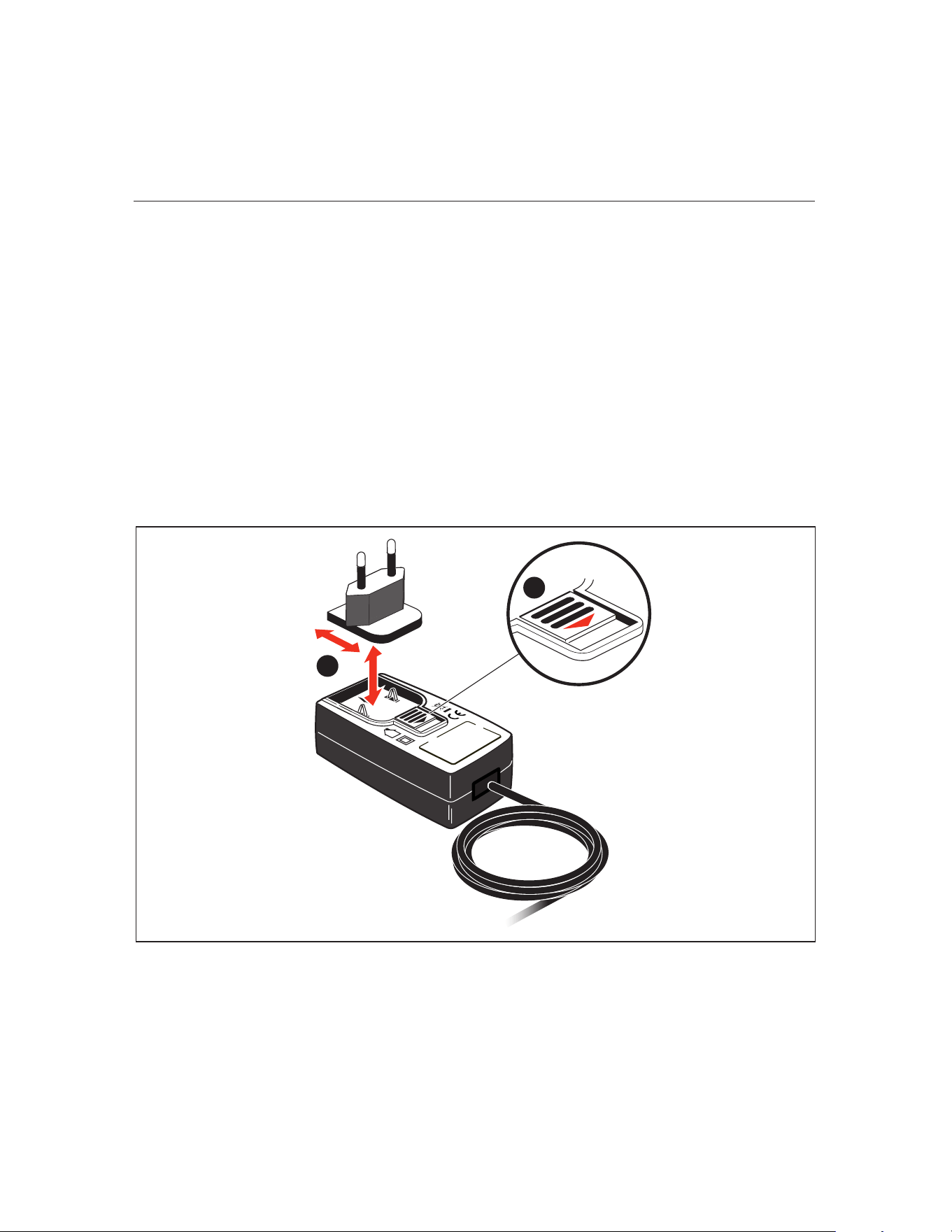
Mounting and dismounting the universal adapter/charger plug
The universal adapter/charger comes with regional plugs for the Euro zone, the
US/Canada/Japan, the UK, Australia and China.
To mount the plug:
1. Push down the latch and hold [
A].
2. Insert the plug into the housing with the lip on the leading edge [
B].
When the latch is pushed down, the arrow inside the charger housing shows
the direction to insert the plug. The plug is locked into position when the latch
release springs back into position.
To dismount a plug, push down the latch [
A]. The plug pops out.
1
2
Figure 4-3. Mounting the charger plug
1.888.610.7664 sales@GlobalTestSupply.com
Fluke-Direct.com

830
Users Manual
8
4. FLUKE 830 - an overview (Change 2)
On pages 18-19, replace the Sensor section with:
Wireless Sensor
The Wireless Sensor mounts using the chain type bracket on the shaft or solid
coupling of the left machine (usually stationary machine) – as viewed from the
normal working position.
The Sensor contains a position detector, which measures the position of the laser
beam as the shafts are rotated. The Sensor also contains an electronic inclinom-
eter for shaft rotation measurements. The semiconductor laser diode within the
Sensor emits a ray of red light (wavelength 630 nm to 680 nm) which is visible at
the point it strikes a surface. The Class 2 laser beam is emitted with a diameter of
approximately 5 mm (3/16”).
The Sensor has two indicator LEDs on the front. See Figure 4-4. Parts of the
Sensor. When facing the sensor, the left LED [
A] indicates the laser beam
adjustment and the charging status. The LED on the right [
B] indicates the
wireless communication status and lights blue when scanning and when commu-
nication is established. See Table 4-2. Monitoring sensor LEDs.
The internal optics and electronics are internally sealed to prevent possible con-
tamination. The Sensor lens, however, must be kept clean. Use the lens cleaning
cloth or a ne dusting brush such as that normally used to clean other optical
devices. Keep the dust cap on when not in use.
An internal rechargeable battery powers the Sensor.
To turn on the Sensor, press the On/O switch on the Sensor. The red LED lights
when sensor is switched on.
To turn o the Sensor, press and hold the On/O switch until both LEDs are o.
Warning
When the Wireless Sensor is on, the laser beam is emitted. DO NOT stare
into the laser beam.
1.888.610.7664 sales@GlobalTestSupply.com
Fluke-Direct.com
9
Addendum
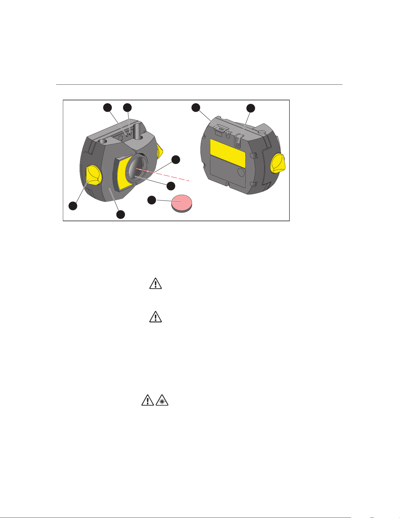
Figure 4-4. Parts of the Sensor
Caution
Avoid polishing the lens too vigorously to prevent irreparable damage to
its anti-reective coating.
Caution
DO NOT remove the six housing torx head screws. Removing the screws
voids the warranty.
Note
Check the calibration accuracy of the Wireless Sensor every two years as in-
dicated by the colored label located on the back of the housing. Return the
Sensor to your authorized service center for calibration.
Warning
Do not stare into the beam.
A
Laser beam status and charging LED; B Laser on/Communication LED;
C Laser beam; D Scratch resistant lens; E Sensor dust cap; FHousing;
G Locking knob; H Micro USB port; I On/O switch
1 8
9
2
3
4
6
7
5
1.888.610.7664 sales@GlobalTestSupply.com
Fluke-Direct.com

830
Users Manual
10
Wireless Sensor LEDs
Table 4-2. Monitoring sensor LEDs
Activity Status / Charging LED (left)
(See [
A] in Figure 4-4)
Laser On / Communication LED (right)
(See [B] in Figure 4-4)
Turn on Lights red for 1 second, then red or green
(depending on the battery capacity) for
another second, then blinks red
Lights blue for 1 second then blinks red (indi-
cating laser emission)
Laser beam
status
Blinks red when laser is OFF
Blinks orange when laser is in END position
Blinks green when laser is centered or in
‘laser OK’ position
When wireless communication is established,
blinks blue once then red three times (indicat-
ing laser emission). This sequence repeats.
Charging Blinks fast green during fast charge (0 % -
90 %)
Blinks slowly green when charge is > 90 %
Steady green when charge is 100 %
1.888.610.7664 sales@GlobalTestSupply.com
Fluke-Direct.com
11
Addendum
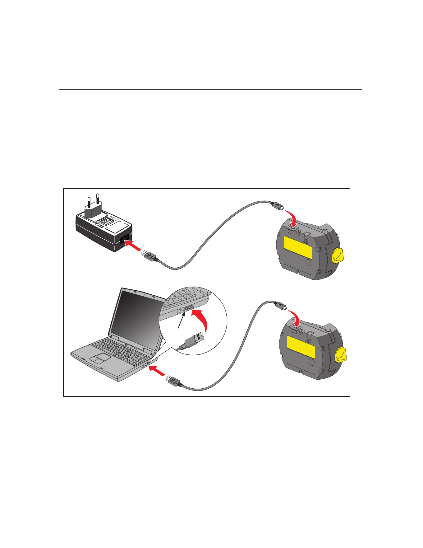
Charging the Wireless Sensor
Use the mains supply or a PC to charge the Sensor.
Note
Charging the Sensor using the mains supply is faster than when charging
through a PC.
Use the supplied micro USB to connect the charging source to the Sensor. (See
Figure 4-8. Charging the non-removable rechargeable battery.)
Figure 4-8. Charging the non-removable rechargeable battery
USB
1.888.610.7664 sales@GlobalTestSupply.com
Fluke-Direct.com
830
Users Manual
12
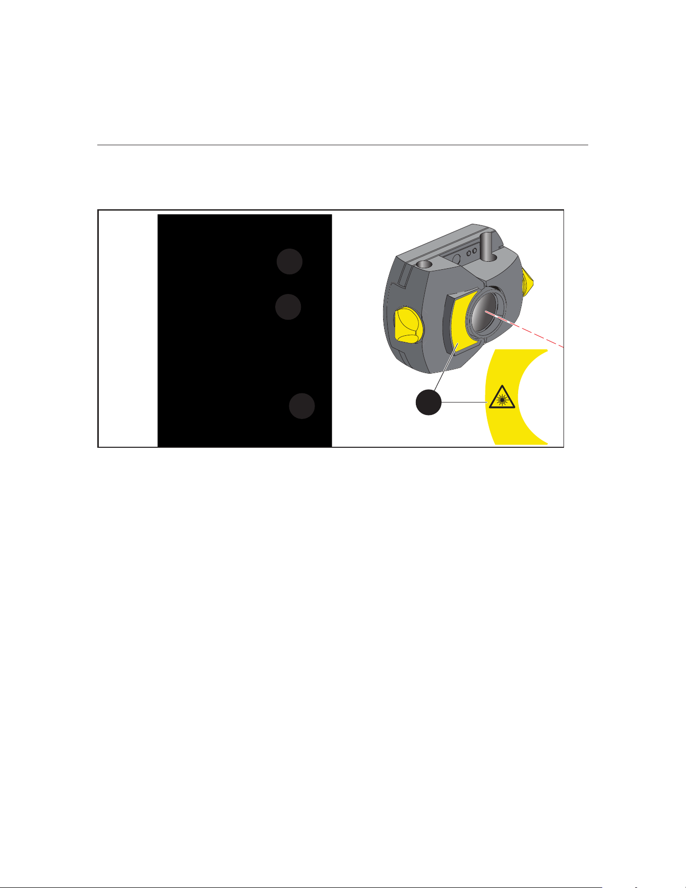
Wireless Sensor and reector labeling
Labels that communicate laser safety and other general information are axed to
the housing of the system components.
Figure 4-9. Labels axed to the measuring components
● A The laser safety warning symbol label is on the front of the Sensor.
● B On the back of the Sensor
• The top label is the laser safety warning.
• The lower label contains the sensor identication, related certication,
and disposal information.
• The round calibration check label shows the calibration check due date;
the black arrow points to the month when the calibration check is due.
The year appears in center of the label. (Not shown.)
The labels contain this text:
LASER RADIATION
DO NOT STARE INTO BEAM
CLASS 2 LASER PRODUCT
P<1 mW, l = 630-680 nm
IEC 60825-1:2014
Complies with 21 CFR 1040.10 and 1040.11 except for deviations pur-
suant to Laser Notice No. 50, dated June 24, 2007
2
2
3
1
1.888.610.7664 sales@GlobalTestSupply.com
Fluke-Direct.com

13
Addendum
Type ALI 21.901 PRÜFTECHNIK GmbH
85737 Ismaning
www.pruftechnik.com
Made in Germany
S.No. 2191 XXXX
Date MM-JJJJ MM-JJJJ
HWS
Contains IC: 5123A-BGTBT121
Contains FCC ID: QOQBT121
Contains Rechargeable Lithium Ion Battery 3.7 V 5 Wh
R 209-J00171
MSIP-CRM-BGT-BT121
● C The label axed on the back of the reector.
The label contains this text:
S.No. XXXX XXXX Opening housing causes
misadjustment and voids
warranty
Type ALI 5.110
HW 1.XX
Made in Germany PRÜFTECHNIK AG
D-85737 Ismaning
1.888.610.7664 sales@GlobalTestSupply.com
Fluke-Direct.com
830
Users Manual
14
6. Getting started (Change 1)
On page 39, replace Set up the product section and the gure with:
Set up the product
1. Prepare the machines by making certain that they are locked out, tagged out
and all necessary safety precautions have been taken.
2. Mount brackets, Sensor, and prism. Mount the Sensor to the left machine
(usually stationary).
3. On the Product, press O and hold until the right LED on the Product lights up
followed by a beep. Shortly after, the Setup screen appears.
Enter dimensions
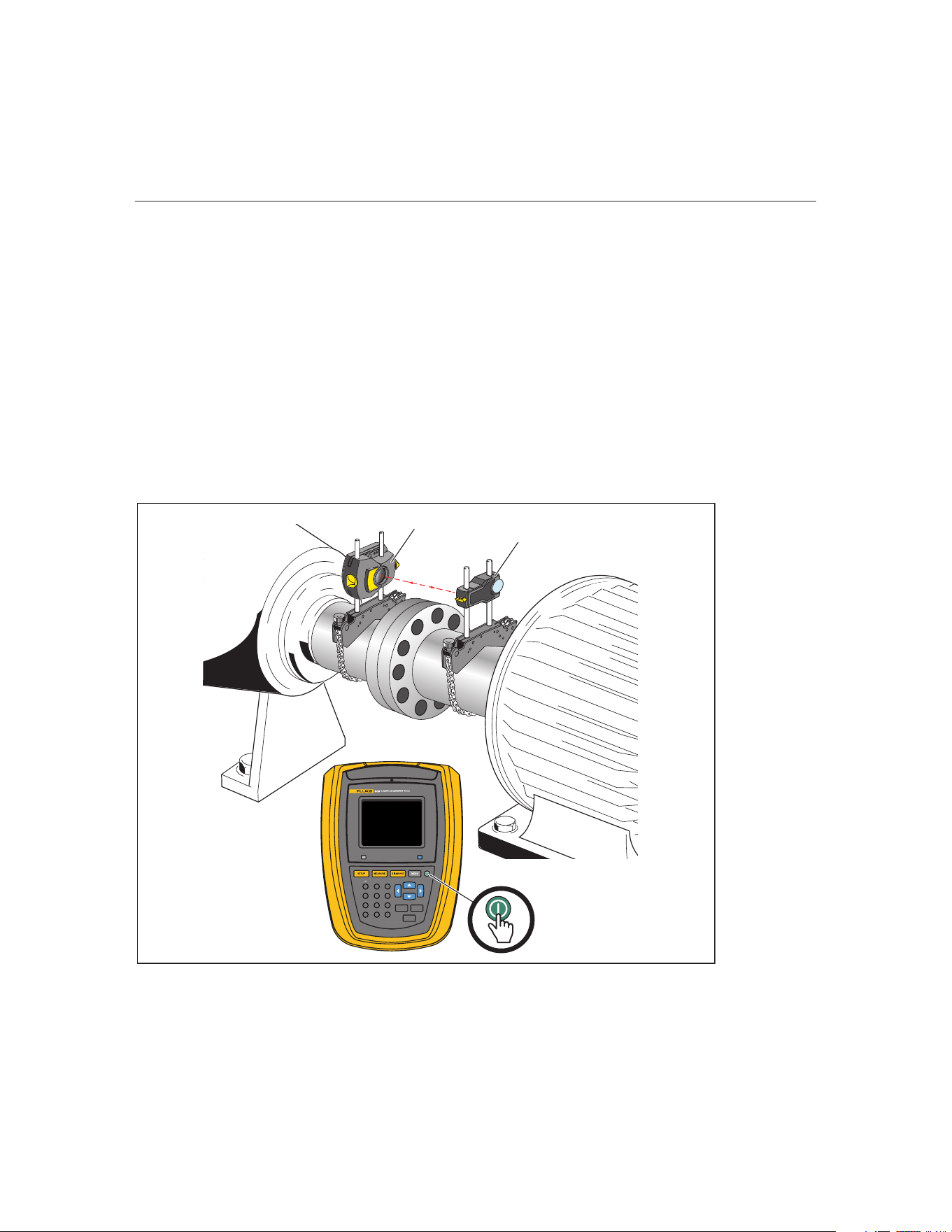
On page 39, replace Figure 6-1 in the Enter dimensions section as follows:
BACK
CLEAR
ENTER
1
4
7
-
+
GHI
PQRS
2
5
8
0
ABC
JKL
TUV
space
3
6
9
DEF
MNO
WXYZ
.
/
*
Fluke 830
Figure 6-1. Mounting components across the coupling
Left machine
(stationary)
Right machine (movable)
Wireless Sensor
Prism
1.888.610.7664 sales@GlobalTestSupply.com
Fluke-Direct.com

15
Addendum
6. Getting started (Change 2)
On page 41, in the Wireless measurement section, replace the text after the note
with:
Press the On/O switch to turn on the Sensor. This initializes the laser beam.
Center the laser dot on the prism dust cap (see Figure 6-2).
On page 43, replace the graphics and text between the graphics with:
Use
/ and highlight ‘Scan’ then press
ENTER
to scan nearby sensors.
Note
Make sure the Sensor is on.
Once detected, the Sensor is selected automatically.
1.888.610.7664 sales@GlobalTestSupply.com
Fluke-Direct.com
830
Users Manual
16
7. Horizontal machine alignment (Change 1)
On pages 50-51, in the Mount wireless module, sensor and prism section,
replace Step 1 through Step 4 including Figure 7-2, then continue the procedure
with Steps 5:
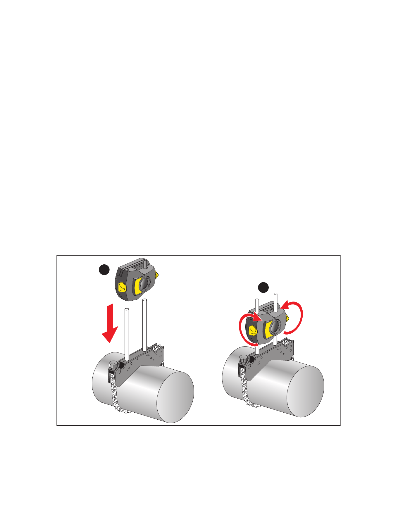
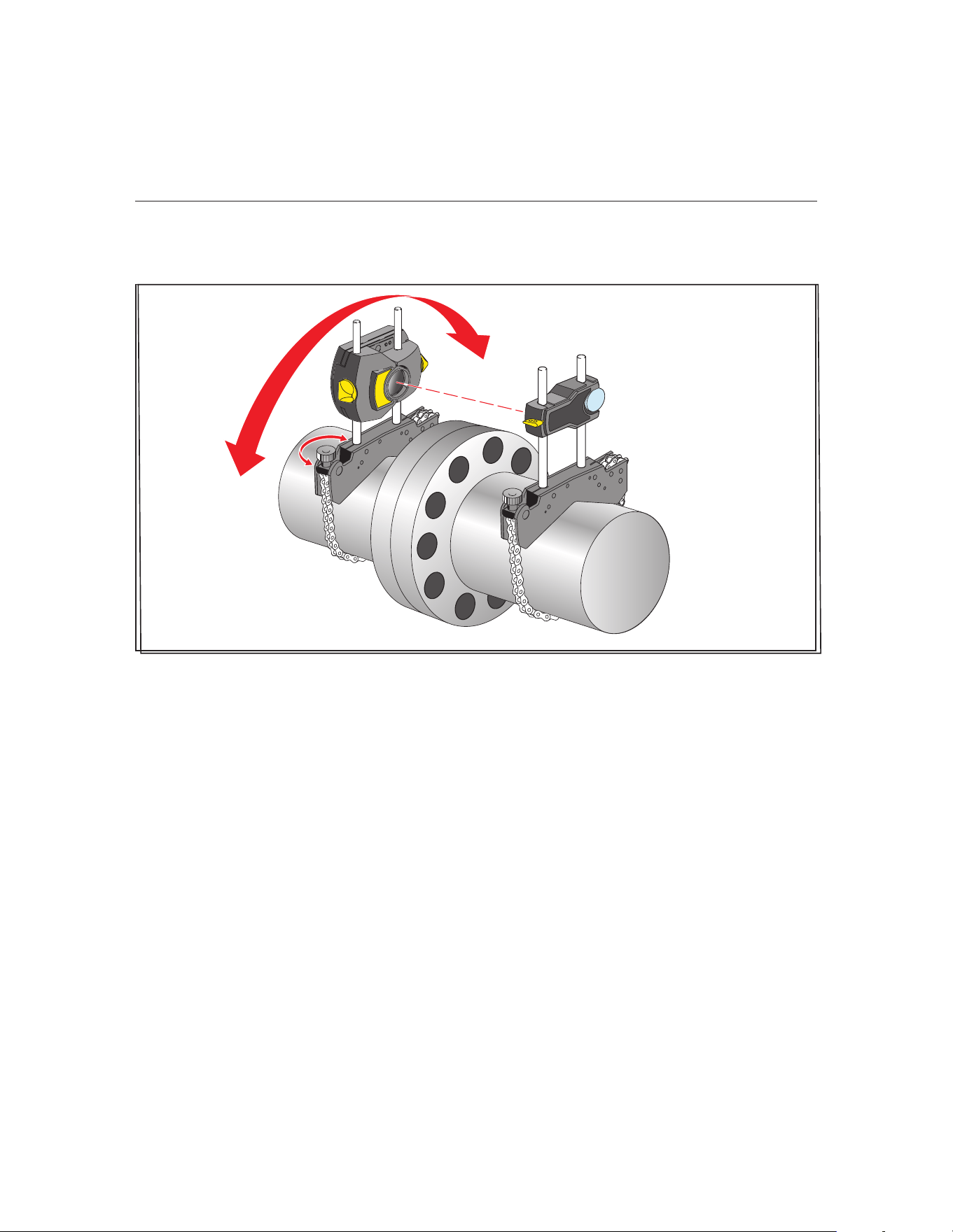
Mount the Wireless Sensor and prism
1. Locate the bracket xed on the shaft of the left machine (usually stationary
machine) – as viewed from normal working position.
2. Mount the Sensor on the support posts of this bracket.
• Note the orientation of the Sensor. The micro USB port must be at the
top. (See Figure 7-2. Mounting the Sensor, Item
A.)
• Loosen the yellow knobs until you can slide the housing onto the support
posts.
3. Tighten the yellow knobs to clamp the Sensor onto the support posts. Do not
overtighten the yellow locking knobs. (See Figure 7-2. Mounting the Sensor
Item
B.)
• Make sure that the laser beam can pass over or through the coupling and
is not blocked.
1
2
Figure 7-2. Mounting the Sensor
1.888.610.7664 sales@GlobalTestSupply.com
Fluke-Direct.com
17
Addendum
7. Horizontal machine alignment (Change 2)
On pages 60-64, replace the Laser beam adjustment section with:
Laser beam adjustment
After entering all required dimensions, the measurement screen appears auto-
matically.
Press the On/O switch to turn on the Sensor. Refer to Table 4-2. Monitoring
sensor LEDs to check the status of the sensor LEDs. The laser is now activated.
Adjust the Sensor and prism so that the laser beam strikes the prism and is
reected back into the Sensor.
7. Horizontal machine alignment (Change 3)
On pages 61-64, replace the Remove prism cap and establish communication
between the sensor and the Product with:
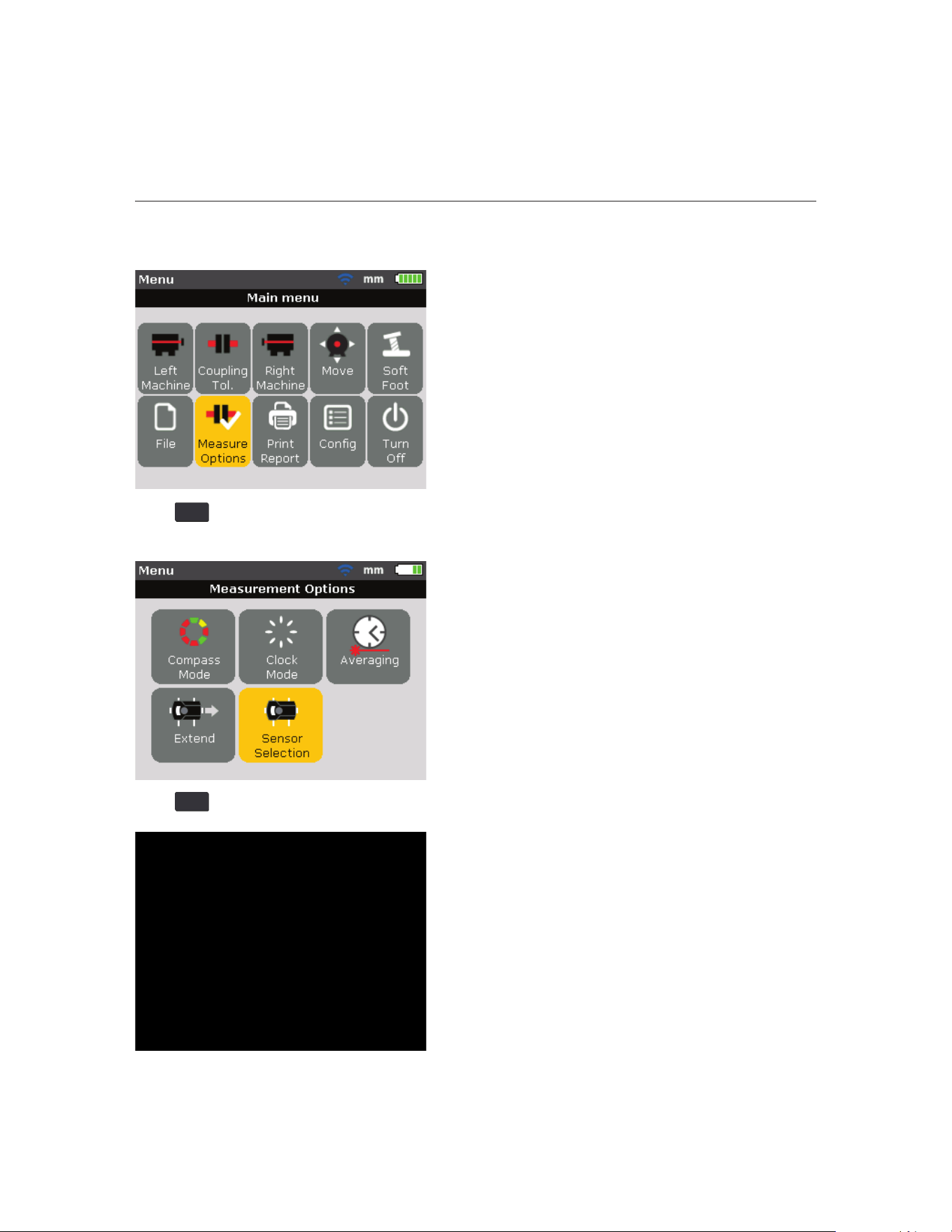
Remove prism cap and establish communication between the
Sensor and the Product
The Product collects measurement data using the Sensor.
Remove the prism dust cap to allow the beam to strike the prism and be reected
back to the Sensor, and then press
MENU
. The “Main menu” window opens. Use
1.888.610.7664 sales@GlobalTestSupply.com
Fluke-Direct.com
830
Users Manual
18
the navigation keys and highlight the icon ‘Measure options’.
Press
ENTER
to conrm the selection. The “Measurement options” window opens.
Use the navigation keys and highlight the icon ‘Sensor selection’.
Press
ENTER
to conrm the selection. The selection window opens.
1.888.610.7664 sales@GlobalTestSupply.com
Fluke-Direct.com

19
Addendum
Use or to highlight ‘Scan’ then press
ENTER
to scan nearby sensors.
Once detected, the Wireless Sensor automatically connects and establishes
communication with the Product.
Note
The serial number of the Sensor in use shows on the screen during measure-
ment.
Now proceed with laser beam adjustment.
The Product remembers the sensors. Select ‘Sensor selection’ to show detected
sensors.
Use
or to highlight the selection and press
ENTER
to conrm the
selection.
1.888.610.7664 sales@GlobalTestSupply.com
Fluke-Direct.com

830
Users Manual
20
You can delete sensor entries. To delete entries, access the ‘Sensor selection’
menu. Use
or to highlight the selection and then press
CLEAR
.
The Product remembers deleted Sensors if the sensor is detected during
scanning.
7. Horizontal machine alignment (Change 4)
On page 65, replace the section, Adjust prism until ONLY the GREEN sensor
LED lights constantly, the Product’s right LED turns blue, with:
Adjust Wireless Sensor and prism until the laser beam status LED
(left) blinks GREEN and the Product’s right LED turns blue
The Status LED (right) indicates the beam adjustment condition. This condition is
simultaneously monitored by the Product’s Communication LED (right).
Note
Make sure that the prism and Sensor lens are clean. Use a soft lint-free cloth. A
lens cleaning cloth is supplied.
1.888.610.7664 sales@GlobalTestSupply.com
Fluke-Direct.com

21
Addendum
Adjust the Sensor and prism so that the laser beam strikes the prism and is
reected back into the Sensor.
Warning
Do not stare into the beam.
1. Keep the prism dust cap on. If the Sensor and prism are roughly positioned
with each other during mounting, the laser beam should strike the prism dust
cap and is readily visible. If the beam is so far o target that the beam misses
the prism completely, hold a sheet of paper in front of the prism to locate the
beam and readjust it.
2. Make these adjustments:
● Vertical adjustment: slide the prism or Sensor up and down along the
support posts. Use the thumbwheel [
A] on the side of the prism housing.
To move the Sensor, loosen the yellow knobs [
B].
The lever [
C] must always be in the horizontal position except for mounting
and dismounting.
Figure 7-9. Horizontal and vertical adjustment of the laser beam
1
2
3
1.888.610.7664 sales@GlobalTestSupply.com
Fluke-Direct.com
830
Users Manual
22
● Horizontal adjustment: loosen one of the brackets on the shaft and rotate it
slightly and then retighten.
Figure 7-15. Horizontal adjustment of the laser beam
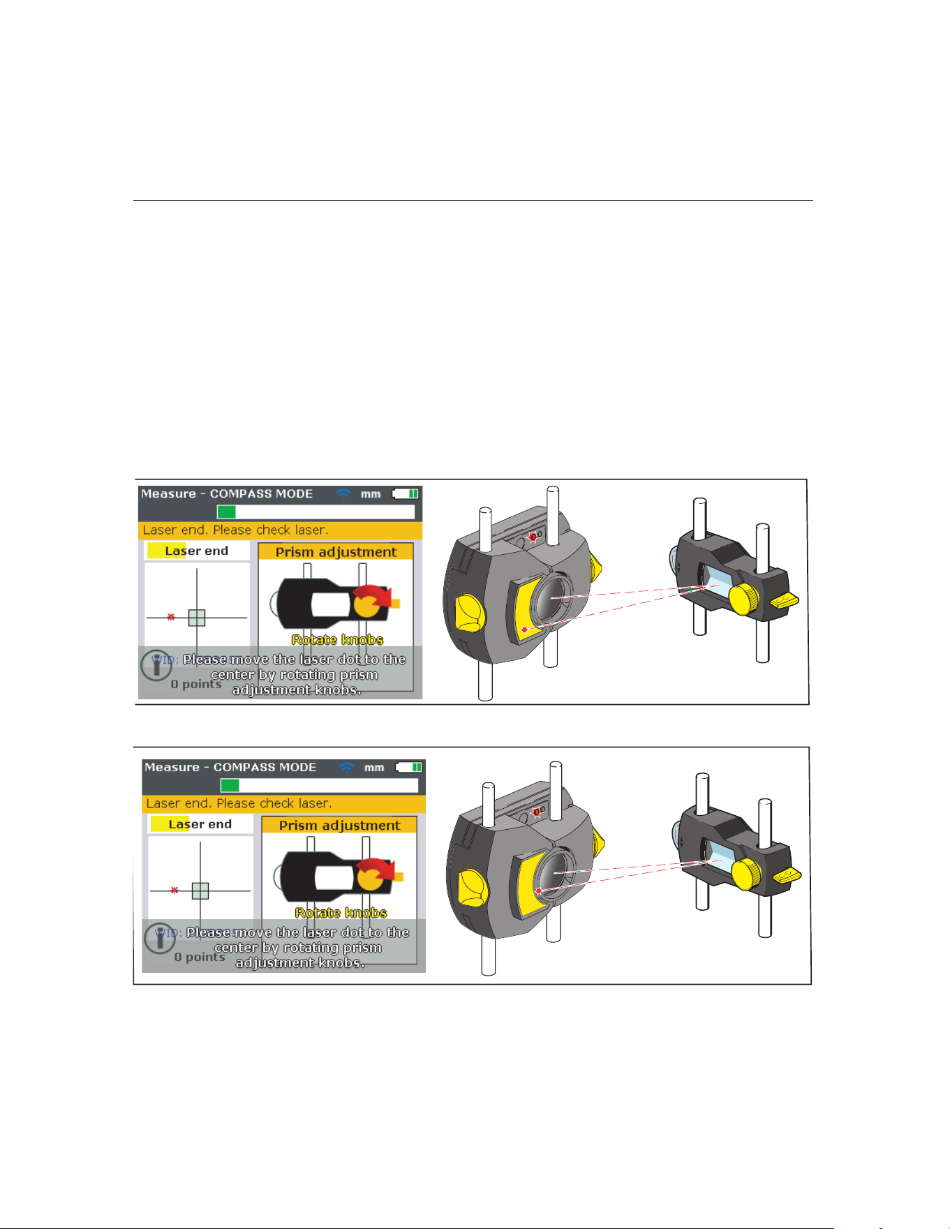
Adust the beam to the center:
1. Position the components until the laser beam strikes the center of the target
on the prism dust cap.
2. Remove the prism dust cap so the laser beam strikes the prism and is
reected back to the Sensor. The Sensor’s Status LED (left) indicates the
beam adjustment condition.
• If the reected beam does not strike the detector surface, the Product’s
right LED turns red while the Sensor Status LED (left) blinks red. (See
Table 4-2. Monitoring sensor LEDs). The message ‘Laser OFF’ appears on
the display screen. Adjust the reected beam using the metal thumbwheel
and the yellow adjustment knob on the prism as shown on Figure 7-9.
Horizontal and vertical adjustment of the laser beam.
• When the reected beam strikes the edge of the detector, the Product’s
right LED turns orange while the Sensor’s Status LED (left) blinks orange
(refer to Table 4-2. Monitoring sensor LEDs). The message ‘Laser End’
appears on the display screen.
1.888.610.7664 sales@GlobalTestSupply.com
Fluke-Direct.com
23
Addendum
7. Horizontal machine alignment (Change 5)
On pages 66-67, replace the section, Center beam such that the Product’s right
LED turns blue section, as follows:
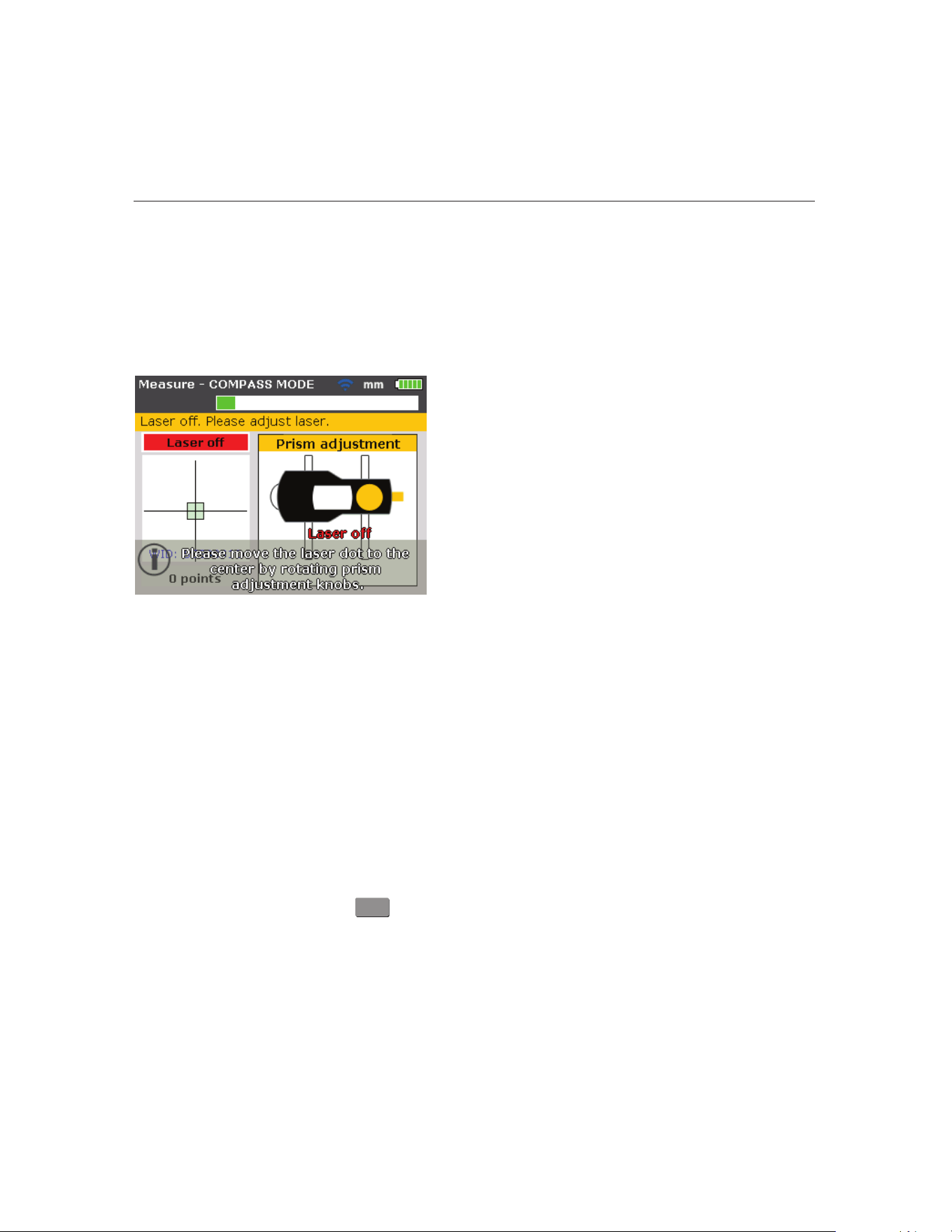
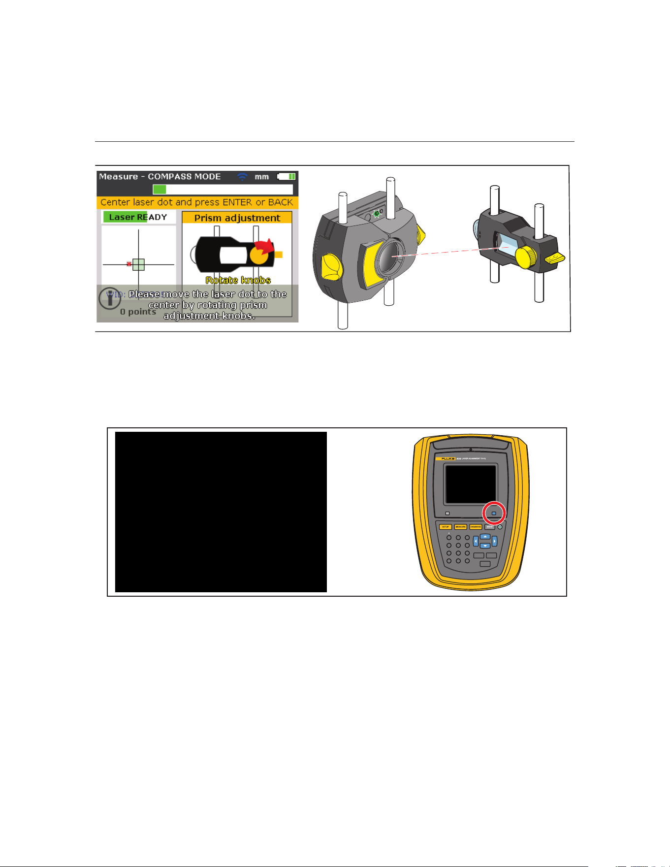
Center beam such that the Product’s right LED turns blue
Adjust the laser beam such that the laser dot on the display screen is positioned
in the green square in the center of the detector display.
● Vertical adjustment: use the side metal thumbwheel.
● Horizontal adjustment: use the yellow prism knob.
The Product’s right LED shows blue.
Laser beam status LED blinks red, and the Product’s RIGHT
LED turns RED
Laser beam status LED blinks orange, and the Product’s RIGHT
LED turns ORANGE
1.888.610.7664 sales@GlobalTestSupply.com
Fluke-Direct.com
830
Users Manual
24
Note
The red arrow on the yellow knob indicates which way to turn the knob. The
closer the beam comes to being centered, the smaller the arrow becomes.
When the laser beam is inside the center square, the Status LED (left) blinks
green.
Note
If the beam is not exactly at the center of the crosshair, it will not aect measure-
ment accuracy. However, maximum range for measurement is available when
the beam is well centered.
Note
Once centered, do not touch the Sensor or prism, as any movement during
measurement will be interpreted as misalignment. You can move these compo-
nents when extending the measurement range.
Laser beam status LED blinks green, and the Product’s RIGHT
LED turns GREEN
BACK
CLEAR
ENTER
1
4
7
-
+
GHI
PQRS
2
5
8
0
ABC
JKL
TUV
space
3
6
9
DEF
MNO
WXYZ
.
/
*
The RIGHT LED turns BLUE
1.888.610.7664 sales@GlobalTestSupply.com
Fluke-Direct.com

