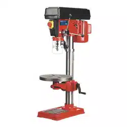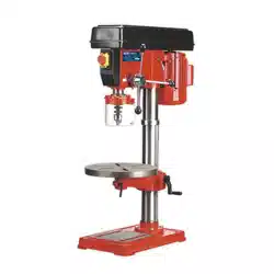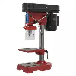

5-SPEED PILLAR DRILL 350W
MODEL NO: SDM30.V2
Thank you for purchasing a Sealey product. Manufactured to a high standard, this product will, if used according to these instructions,
and properly maintained, give you years of trouble free performance.
IMPORTANT: PLEASE READ THESE INSTRUCTIONS CAREFULLY. NOTE THE SAFE OPERATIONAL REQUIREMENTS, WARNINGS & CAUTIONS. USE
THE PRODUCT CORRECTLY AND WITH CARE FOR THE PURPOSE FOR WHICH IT IS INTENDED. FAILURE TO DO SO MAY CAUSE DAMAGE AND/OR
PERSONAL INJURY AND WILL INVALIDATE THE WARRANTY. KEEP THESE INSTRUCTIONS SAFE FOR FUTURE USE.
1. SAFETY
1.1. ELECTRICAL SAFETY
WARNING! It is the user’s responsibility to check the following:
9 Check all electrical equipment and appliances to ensure that they are safe before using. Inspect power supply leads, plugs
and all electrical connections for wear and damage. Sealey recommend that an RCD (Residual Current Device) is used with
all electrical products.
Electrical safety information. It is important that the following information is read and understood:
9 Ensure that the insulation on all cables and on the appliance is safe before connecting it to the power supply.
9 Regularly inspect power supply cables and plugs for wear or damage and check all connections to ensure that they are secure.
Important: Ensure that the voltage rating on the appliance suits the power supply to be used and that the plug is tted with the correct fuse.
8 DO NOT pull or carry the appliance by the power cable.
8 DO NOT pull the plug from the socket by the cable.
8 DO NOT use worn or damaged cables, plugs or connectors. Ensure that any faulty item is repaired or is replaced
immediately by a qualied electrician.
If the cable or plug is damaged during use, switch off the electricity supply and remove from use.
Ensure that repairs are carried out by a qualied electrician.
1.2. GENERAL SAFETY
WARNING! Disconnect drill from mains power before changing accessories, servicing or performing any maintenance.
9 Maintain the drill in good condition (use an authorised service agent).
WARNING! Keep all guards and holding screws in place, tight and in good working order. Check regularly for damaged parts.
A guard, or any other part, that is damaged should be repaired/replaced before the tool is used, to ensure that it will operate
properly and perform its intended function. The safety guard is a mandatory fitting where drill is used in premises covered by
the Health & Safety at Work Act.
9 Check alignment of moving parts and check for possible broken parts.
9 Replace or repair damaged parts. Use recommended parts only. Non-authorised parts may be dangerous and will invalidate the warranty.
9 Ensure the set screws of the head frame are tight before using the drill.
9 Secure the drill to a supporting structure to avoid the machine tipping, sliding or walking.
9 Drill is designed for use with drill bits only. No other accessory may be used.
9 Ensure the chuck is securely fastened to the spindle.
9 Remove adjusting keys and wrenches from the machine and working area before switching on.
9 Use clamps or a vice (not included) to secure the work piece. Available from your Sealey stockist.
8 DO NOT secure the work piece by hand.
9 Refer to speed chart for recommended drilling speeds.
WARNING! Always wear approved eye or face protection when operating this drill. Use a face or dust mask if dust is generated.
WARNING! DO NOT wear gloves when drilling.
9 Others in the workplace should keep a safe distance from the drill, especially when it is in operation.
9 Keep the work area as childproof as possible by using padlocks and master switches.
9 Keep drill bits clean and sharp for best and safest performance. Follow the instructions for lubrication and changing accessories.
9 Remove ill fitting clothing. Remove ties, watches, rings and other loose jewellery and contain long hair.
9 Locate the drill in a suitable working area, keep area clean and tidy and free from unrelated materials. Ensure there is adequate lighting.
9 Maintain correct balance and footing. Ensure the floor is not slippery and wear non-slip shoes.
9 Avoid unintentional starting.
8 DO NOT force the drill to achieve a task it was not designed to perform.
8 DO NOT allow untrained persons to operate the drill.
8 DO NOT get the drill wet or use in damp or wet locations or areas where there is condensation.
8 DO NOT operate the drill if damaged.
8 DO NOT use drill in an area where paint fumes, solvents or flammable liquids pose a potential hazard. Keep flammable material away
from the drill when operating. Flammable waste, such as wiping or cleaning rags, must be placed in a closed metal container and
disposed of correctly.
8 DO NOT exceed the rated capacity of the drill.
8 DO NOT operate the drill if any parts are missing as this may cause failure and/or personal injury.
Refer to
Instruction
Manual
Wear eye
protection
Original Language Version
© Jack Sealey Limited
SDM30.V2 Issue 6 (H,2,F) 31/01/24

8 DO NOT leave the drill operating unattended.
8 DO NOT operate the drill when you are tired, under the influence of alcohol, drugs or intoxicating medication.
8 DO NOT pull the cable from the power supply.
9 When not in use switch the drill off, remove plug from the power supply and do not leave until the tool has come to a complete stop.
2. INTRODUCTION
Compact bench drill powerful enough to cut through wood, plastic and metal. Easy to operate, smooth and quiet in operation. 5-Speed
settings between 580 and 2650rpm. Safety is ensured by protection guard, no-volt safety switch and access to drive belt is denied during
operation by mechanical protection.
3. SPECIFICATION
4. CONTENTS
Unpack the parts listed below and check to ensure they are in good condition. Any queries must be reported to your stockist immediately.
Head Assembly Base Chuck and Key
Column with Flange Feed Handles and Knobs (3) Table and Bracket
3 Bolts and Washers Safety Guard Hex. Keys (2)
5. ASSEMBLY
NOTE: Figures are illustrative and may differ in detail from your drill.
5.1. Place the column assembly on the base, align holes and secure with the three screws and washers provided.
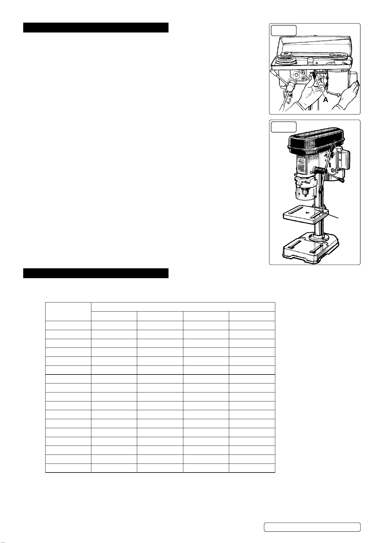
5.2. Install the table onto the column and tighten clamp screw (fig.1.A).
5.3. Carefully place the head assembly over the column and slide it into position. Align head with base.
5.4. Tighten the two set screws in the right side of the head to lock it into position (fig.2).
5.5. Screw the three feed handles and knobs into the pinion shaft (fig.3.A).
5.6. To install chuck open the chuck jaws completely by turning the chuck key counter-clockwise. Place a piece of wood on the drill table (to
prevent the chuck from getting damaged).
5.7. Fit chuck to protruding end of spindle and hold in place (fig.3.B).
5.8. Turn feed handles to bring nose of chuck down onto wood (fig.3). Firmly pull on feed handle to seat the spindle taper in the chuck.
5.9. The safety guard mounting is pre-fitted to the drill head. Remove the three small screws in the guard support channel, insert the guard and
refit the screws, through the holes provided in the guard. Note that the guard is in two parts held together by two screws and wing nuts.
For packaging purposes these are supplied with the wing nuts on the inside of the guard. Before use remove screws and wing nuts and
refit so that wing nuts are on the outside and accessible.
5.10. DRILL MOUNTING
5.10.1. For stability and safety it is important that the drill base is securely bolted to the workbench.
5.10.2. Ensure that the mounting surface is capable of supporting the drill together with the weight of the heaviest likely work piece.
FIG.1
FIG.2 FIG.3
MODEL NO:
SDM30.V2
Drilling Capacity (Chuck Size):
13mm
Spindle Nose Taper:
MT2
Swing:
208mm
Spindle centre to column:
104mm
Spindle travel:
50mm
Number of speeds:
5
Speed range:
580-2650rpm
Maximum Distance Spindle to Table:
200mm
Maximum Distance Spindle to Base:
290mm
Working Table Surface size:
158 x 160mm
Working Base Surface size:
138 x 180mm
Base Size:
200 x 310mm
Column diameter:
46mm
Collar diameter:
40mm
Overall Height:
580mm
Motor Power:
185W(350W)
Supply
230V
Original Language Version
© Jack Sealey Limited
SDM30.V2 Issue 6 (H,2,F) 31/01/24
6. OPERATION
6.1. INSTALL DRILL BIT
WARNING! Ensure the drill is unplugged from the mains power supply before
commencing.
6.1.1. Insert drill bit into chuck jaws to 1” (25mm) deep (avoid inserting small bits too far) and centre
bit in chuck before tightening jaws with chuck key.
6.2. ADJUSTING THE TABLE
6.2.1. To adjust table up, down or round the column, loosen clamp bolt (fig.1.A). Move table to
required position and tighten clamp bolt (fig.1.A).
6.2.2. To adjust table tilt, loosen the work table bolt (fig.1.B), adjust to the desired angle using the
angle scale, then re-tighten.
6.3. ADJUSTING THE SPEED
6.3.1. Open the pulley cover and loosen the belt tension lock screw (fig.4.A).
6.3.2. Choose the speed for drilling operation (see drill speed chart) and move the belt to the correct
position for that speed, as shown on the chart inside the pulley cover.
6.4. BELT TENSION
6.4.1. With the belt tension lock screw (fig.4.A) loosened the motor plate spring will automatically
give the correct belt tension (belt give of approx. 13mm under finger pressure). Tighten lock
screw and close pulley cover.
6.5. POSITIONING THE WORK PIECE
6.5.1. Use a piece of wood to rest the work piece on. The drill bit may break through the work
piece and damage the table otherwise.
6.5.2. The wood should rest on the table so that one end of it is against the left side of the column.
When the drill bit breaks through the work piece, it will contact the wood and cause it to spin.
Resting the wood against the column will prevent this.
6.5.3. For small work pieces that cannot be clamped to the table, use a drill vice (not included). Vice
must be clamped or bolted to table.
6.6. SETTING DRILL DEPTH
6.6.1. Use the scale at the front of the drill head.
6.6.2. Loosen lock nuts on threaded rod and adjust so that at desired drill depth, nuts contact head
lug and prevent further drill movement. Tighten lock nuts.
6.6.3. When ready to drill, simply pull the feed handle. The drill feed will stop at the set depth.
6.7. GUARD
6.7.1. Always adjust guard length, by loosening wing nut at each side (g.5.A), to give maximum
protection before starting to drill.
7. DRILL SPEEDS
The chart below shows recommended drill speeds for various bit diameters and materials. Select the available drill speed that is the same
as, or nearest to, the one recommended for the task in hand.
Drill Dia. (mm)
Drill speed (rpm)
Steel Cast Iron Iron Alum. & Copper
3 1820 2580 2580 2580
4 1350 1820 1820 2580
5 1290 1350 1350 2580
6 970 1290 1290 2580
7 830 970 970 2580
8 830 970 970 2580
9 500 970 830 1820
10 500 830 830 1820
11 500 830 830 1820
12 420 830 500 1820
13 420 500 500 1350
14 420 500 500 1350
16 320 500 500 1290
18 320 420 420 1290
20 280 320 320 970
22 210 320 280 970
25 120 280 210 830
FIG.4
FIG.5
A
Original Language Version
© Jack Sealey Limited
SDM30.V2 Issue 6 (H,2,F) 31/01/24
8. MAINTENANCE
8.1. Clean the tool after each use. A coat of car type wax applied to the table and column will help to keep the surfaces clean.
8.2. Blow out any dust that may have accumulated in the motor.
8.3. Periodically lubricate all moving parts.
9. TROUBLESHOOTING
PROBLEM POSSIBLE CAUSES SOLUTION
Excessive noise 1. Incorrect belt tension
2. Spindle is dry
3. Pulley is loose
4. Bearing damaged
1. Adjust tension
2. Disassemble spindle/quill and lubricate
3. Tighten pulley
4. Replace the bearing
Excessive drill wobble 1. Chuck is loose
2. Bearing or spindle shaft is worn
3. Chuck is worn
1. Tighten the chuck by pressing it against the table (see 5.6 and 5.8)
2. Replace worn part
3. Replace the chuck
Drill binds in the work
piece
1. Feed pressure is wrong
2. Belt is loose
3. Drill is loose
4. Speed is too fast
1. Apply less pressure
2. Adjust tension
3. Tighten the drill with the key
4. Change the speed
Drill burns or smokes 1. Speed is too fast
2. Chips are not discharging
3. Drill bit is dull
4. Lubrication needed for work
5. Feed pressure is wrong
1. Change the speed
2. Clean the drill
3. Use a new bit
4. Lubricate whilst drilling
5. Apply less pressure
Table is difficult to move 1. Lubrication is needed 1. Lubricate with light oil
Original Language Version
© Jack Sealey Limited
SDM30.V2 Issue 6 (H,2,F) 31/01/24
Sealey Group, Kempson Way, Suffolk Business Park, Bury St Edmunds, Suffolk. IP32 7AR
01284 757500 sales@sealey.co.uk www.sealey.co.uk
WEEE REGULATIONS
Dispose of this product at the end of its working life in compliance with the EU Directive on Waste Electrical and Electronic
Equipment (WEEE). When the product is no longer required, it must be disposed of in an environmentally protective way. Contact
your local solid waste authority for recycling information.
ENVIRONMENT PROTECTION
Recycle unwanted materials instead of disposing of them as waste. All tools, accessories and packaging should be
sorted, taken to a recycling centre and disposed of in a manner which is compatible with the environment. When
the product becomes completely unserviceable and requires disposal, drain any uids (if applicable) into approved
containers and dispose of the product and uids according to local regulations.
REGISTER YOUR
PURCHASE HERE
Note: It is our policy to continually improve products and as such we reserve the right to alter data, specications and component parts
without prior notice. Please note that other versions of this product are available. If you require documentation for alternative versions, please
email or call our technical team on technical@sealey.co.uk or 01284 757505.
Important: No Liability is accepted for incorrect use of this product.
Warranty: Guarantee is 12 months from purchase date, proof of which is required for any claim.