
2MP ColorVu Smart Hybrid
Light Audio Fixed
Bullet & Turret Camera
User Manual
User Manual
Thank you for purchasing our product. If there are any
questions, or requests, do not hesitate to contact the
dealer.
This manual applies to the models below:
Type
Model
Type I Camera
DS-2CE10DF0T-LFS
DS-2CE10DF0T-LPFS
Type II Camera
DS-2CE12DF0T-LFS
Type III Camera
DS-2CE70DF0T-LPFS
Type IV Camera
DS-2CE70DF0T-LMFS
Type V Camera
DS-2CE72DF0T-LFS
This manual may contain several technical mistakes or
printing errors, and the content is subject to change
without notice. The updates will be added to the new
version of this manual. We will readily improve or update
the products or procedures described in the manual.
01040020230322

Initiatives on the Use of Video Products
Thank you for choosing Hikvision products.
Technology affects every aspect of our life. As a high-tech
company, we are increasingly aware of the role
technology plays in improving business efficiency and
quality of life, but at the same time, the potential harm of
its improper usage. For example, video products are
capable of recording real, complete and clear images. This
provides a high value in retrospect and preserving real-
time facts. However, it may also result in the infringement
of a third party’s legitimate rights and interests if
improper distribution, use and/or processing of video
data takes place. With the philosophy of “Technology for
the Good”, Hikvision requests that every end user of
video technology and video products shall comply with all
the applicable laws and regulations, as well as ethical
customs, aiming to jointly create a better community.
Please read the following initiatives carefully:
1. Everyone has a reasonable expectation of privacy,
and the installation of video products should not be
in conflict with this reasonable expectation.
Therefore, a warning notice shall be given in a
reasonable and effective manner and clarify the
monitoring range, when installing video products in
public areas. For non-public areas, a third party’s
rights and interests shall be evaluated when
installing video products, including but not limited
to, installing video products only after obtaining the
consent of the stakeholders, and not installing
highly-invisible video products.
2. The purpose of video products is to record real
activities within a specific time and space and under
specific conditions. Therefore, every user shall first
reasonably define his/her own rights in such specific
scope, in order to avoid infringing on a third party’s
portraits, privacy or other legitimate rights.
3. During the use of video products, video image data
derived from real scenes will continue to be
generated, including a large amount of biological
data (such as facial images), and the data could be
further applied or reprocessed. Video products
themselves could not distinguish good from bad
regarding how to use the data based solely on the
images captured by the video products. The result
of data usage depends on the method and purpose
of use of the data controllers. Therefore, data
controllers shall not only comply with all the
applicable laws and regulations and other
normative requirements, but also respect
international norms, social morality, good morals,
common practices and other non-mandatory
requirements, and respect individual privacy,
portrait and other rights and interests.
4. The rights, values and other demands of various
stakeholders should always be considered when
processing video data that is continuously
generated by video products. In this regard, product
security and data security are extremely crucial.
Therefore, every end user and data controller, shall
undertake all reasonable and necessary measures
to ensure data security and avoid data leakage,
improper disclosure and improper use, including
but not limited to, setting up access control,
selecting a suitable network environment (the
Internet or Intranet) where video products are
connected, establishing and constantly optimizing
network security.
Video products have made great contributions to the
improvement of social security around the world, and we

believe that these products will also play an active role in
more aspects of social life. Any abuse of video products in
violation of human rights or leading to criminal activities
are contrary to the original intent of technological
innovation and product development. Therefore, each
user shall establish an evaluation and tracking mechanism
of their product application to ensure that every product
is used in a proper and reasonable manner and with good
faith.

© 2022 Hangzhou Hikvision Digital Technology Co., Ltd.
All rights reserved.
About this Manual
The Manual includes instructions for using and managing
the Product. Pictures, charts, images and all other
information hereinafter are for description and
explanation only. The information contained in the
Manual is subject to change, without notice, due to
firmware updates or other reasons. Please find the latest
version of this Manual at the Hikvision website
(https://www.hikvision.com/).
Please use this Manual with the guidance and assistance
of professionals trained in supporting the Product.
Trademarks
and other Hikvision’s trademarks and
logos are the properties of Hikvision in various
jurisdictions.
Other trademarks and logos mentioned are the
properties of their respective owners.
Disclaimer
TO THE MAXIMUM EXTENT PERMITTED BY APPLICABLE
LAW, THIS MANUAL AND THE PRODUCT DESCRIBED, WITH
ITS HARDWARE, SOFTWARE AND FIRMWARE, ARE
PROVIDED “AS IS” AND “WITH ALL FAULTS AND ERRORS”.
HIKVISION MAKES NO WARRANTIES, EXPRESS OR
IMPLIED, INCLUDING WITHOUT LIMITATION,
MERCHANTABILITY, SATISFACTORY QUALITY, OR FITNESS
FOR A PARTICULAR PURPOSE. THE USE OF THE PRODUCT
BY YOU IS AT YOUR OWN RISK. IN NO EVENT WILL
HIKVISION BE LIABLE TO YOU FOR ANY SPECIAL,
CONSEQUENTIAL, INCIDENTAL, OR INDIRECT DAMAGES,
INCLUDING, AMONG OTHERS, DAMAGES FOR LOSS OF
BUSINESS PROFITS, BUSINESS INTERRUPTION, OR LOSS OF
DATA, CORRUPTION OF SYSTEMS, OR LOSS OF
DOCUMENTATION, WHETHER BASED ON BREACH OF
CONTRACT, TORT (INCLUDING NEGLIGENCE), PRODUCT
LIABILITY, OR OTHERWISE, IN CONNECTION WITH THE
USE OF THE PRODUCT, EVEN IF HIKVISION HAS BEEN
ADVISED OF THE POSSIBILITY OF SUCH DAMAGES OR
LOSS.
YOU ACKNOWLEDGE THAT THE NATURE OF THE INTERNET
PROVIDES FOR INHERENT SECURITY RISKS, AND
HIKVISION SHALL NOT TAKE ANY RESPONSIBILITIES FOR
ABNORMAL OPERATION, PRIVACY LEAKAGE OR OTHER
DAMAGES RESULTING FROM CYBER-ATTACK, HACKER
ATTACK, VIRUS INFECTION, OR OTHER INTERNET
SECURITY RISKS; HOWEVER, HIKVISION WILL PROVIDE
TIMELY TECHNICAL SUPPORT IF REQUIRED.
YOU AGREE TO USE THIS PRODUCT IN COMPLIANCE WITH
ALL APPLICABLE LAWS, AND YOU ARE SOLELY
RESPONSIBLE FOR ENSURING THAT YOUR USE
CONFORMS TO THE APPLICABLE LAW. ESPECIALLY, YOU
ARE RESPONSIBLE, FOR USING THIS PRODUCT IN A
MANNER THAT DOES NOT INFRINGE ON THE RIGHTS OF
THIRD PARTIES, INCLUDING WITHOUT LIMITATION,
RIGHTS OF PUBLICITY, INTELLECTUAL PROPERTY RIGHTS,
OR DATA PROTECTION AND OTHER PRIVACY RIGHTS. YOU
SHALL NOT USE THIS PRODUCT FOR ANY PROHIBITED
END-USES, INCLUDING THE DEVELOPMENT OR
PRODUCTION OF WEAPONS OF MASS DESTRUCTION, THE
DEVELOPMENT OR PRODUCTION OF CHEMICAL OR
BIOLOGICAL WEAPONS, ANY ACTIVITIES IN THE CONTEXT
RELATED TO ANY NUCLEAR EXPLOSIVE OR UNSAFE
NUCLEAR FUEL-CYCLE, OR IN SUPPORT OF HUMAN
RIGHTS ABUSES.
IN THE EVENT OF ANY CONFLICTS BETWEEN THIS
MANUAL AND THE APPLICABLE LAW, THE LATTER
PREVAILS.
Regulatory Information
EU Conformity Statement
This product and - if applicable - the
supplied accessories too are marked with
"CE" and comply therefore with the
applicable harmonized European standards
listed under the Directive 2014/30/EU (EMCD), Directive
2001/95/EC (GPSD) and Directive 2011/65/EU (RoHS).
2012/19/EU (WEEE directive): Products
marked with this symbol cannot be
disposed of as unsorted municipal waste in
the European Union. For proper recycling,
return this product to your local supplier
upon the purchase of equivalent new
equipment, or dispose of it at designated collection
points. For more information see: www.recyclethis.info.
2006/66/EC (battery directive): This product contains a
battery that cannot be disposed of as
unsorted municipal waste in the European
Union. See the product documentation for
specific battery information. The battery is
marked with this symbol, which may
include lettering to indicate cadmium (Cd), lead (Pb), or
mercury (Hg). For proper recycling, return the battery to
your supplier or to a designated collection point. For
more information, see: www.recyclethis.info.
Industry Canada ICES-003 Compliance
This device meets the CAN ICES-3 (A)/NMB-3(A)
standards requirements.
Warning
This is a class A product. In a domestic environment this
product may cause radio interference in which case the
user may be required to take adequate measures.
Safety Instruction
These instructions are intended to ensure that user can
use the product correctly to avoid danger or property
loss.
The precaution measure is divided into “Warnings” and
“Cautions”.
Warnings: Serious injury or death may occur if any of the
warnings are neglected.
Cautions: Injury or equipment damage may occur if any
of the cautions are neglected.
Warnings
Warnings Follow
these safeguards to
prevent serious injury
or death.
Cautions Follow these
precautions to prevent
potential injury or
material damage.
In the use of the device, you must be in strict
compliance with the electrical safety regulations of the
nation and region.
Input voltage should meet both the SELV (Safety Extra
Low Voltage) and the Limited Power Source with 12
VDC according to the IEC60950-1 and IEC62368-1
standard. Refer to technical specifications for detailed
information.
Do not connect multiple devices to one power adapter
to avoid over-heating or a fire hazard caused by
overload.
Make sure that the plug is firmly connected to the
power socket.
Make sure that the device is firmly fixed if wall
mounting or ceiling mounting is adopted.
If smoke, odor or noise rise from the device, turn off
the power at once and unplug the power cord, and
then contact the service center.
Never attempt to disassemble the camera by
unprofessional personal.
Cautions
Do not drop the camera or subject it to physical shock.
Do not touch senor modules with fingers.
Do not place the camera in extremely hot, cold (the
operating temperature shall be -40°C to 60°C), dusty or
damp locations, and do not expose it to high
electromagnetic radiation.
If cleaning is necessary, use clean cloth with a bit of
ethanol and wipe it gently.
Do not aim the camera at the sun or extra bright places.
The sensor may be burned out by a laser beam, so
when any laser equipment is in using, make sure that
the surface of sensor will not be exposed to the laser
beam.
Do not expose the device to high electromagnetic
radiation or extremely hot, cold, dusty or damp
environment.
To avoid heat accumulation, good ventilation is
required for the operating environment.
Keep the camera away from liquid while in use for non-
water-proof device.
While in delivery, the camera shall be packed in its
original packing, or packing of the same texture.
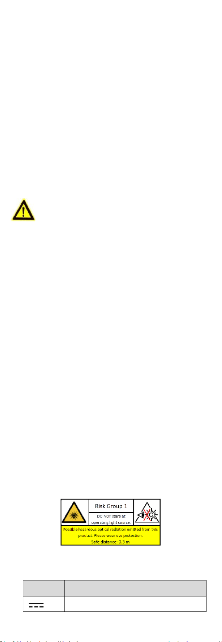
The beam of the light at the distance of 200 mm is
classified as Risk Group 1 (RG1). Possible hazardous
optical radiation emitted from this product.
DO NOT stare at operating light source. May be harmful
to the eyes.
Wear appropriate eye protection or turn on the
supplement light only at a safe distance (0.3 m) or in
the area that is not directly exposed to the light when
installing or maintaining the device.
Mark Description
Table 0-1 Mark Description
Mark
Description
DC Voltage
1 Introduction
1.1 Product Features
The main features are as follows:
High performance CMOS sensor
OSD menu with configurable parameters
24-hour color image
Smart light
3-axis adjustment
1.2 Overview
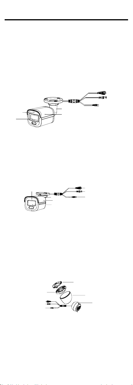
1.2.1 Overview of Type I Camera
Power Cord
Video Cable
Switch Button
Bracket
Main Body
Lens
Microphone
Figure 1-1 Overview of Type I Camera
Note:
Press and hold the switch button for 5 seconds to switch
the video output. Four kinds of video outputs are
available: TVI, AHD, CVI, and CVBS
1.2.2 Overview of Type II Camera
Power Cord
Video Cable
Switch Button
Bracket
Main Body
Lens
Microphone
Figure 1-2 Overview of Type II Camera
Note:
Press and hold the switch button for 5 seconds to switch
the video output. Four kinds of video outputs are
available: TVI, AHD, CVI, and CVBS.
1.2.3 Overview of Type III Camera
DC12VIN
Video Cable
Switch Button
Power Cord
Base
Gang Box
Enclosure
Main Body
Microphone
Figure 1-3 Overview of Type III Camera
Note:
Press and hold the switch button for 5 seconds to switch
the video output. Four kinds of video outputs are
available: TVI, AHD, CVI, and CVBS.
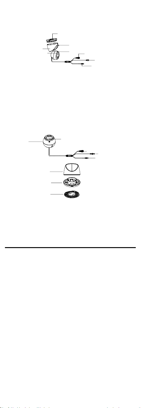
1.2.4 Overview of Type IV Camera
Enclosure
Base
Set Screw
Main Body
Video Cable
Switch Button
Power Cord
DC12VIN
Microphone
Figure 1-4 Overview of Type IV Camera
Note:
Press and hold the switch button for 5 seconds to switch
the video output. Four kinds of video outputs are
available: TVI, AHD, CVI, and CVBS.
1.2.5 Overview of Type V Camera
Enclosure
Base
Gang Box
Main
Body
Power Cord
Switch Button
Video Cable
Microphone
Figure 1-5 Overview of Type V Camera
Note:
Press and hold the switch button for 5 seconds to switch
the video output. Four kinds of video outputs are
available: TVI, AHD, CVI, and CVBS.
2 Installation
Before you start
Make sure that the device in the package is in good
condition and all the assembly parts are included.
Make sure that all the related equipment is power-off
during the installation.
Check the specification of the products for the
installation environment.
Check whether the power supply is matched with your
power output to avoid damage.
Make sure the wall is strong enough to withstand three
times the weight of the camera and the mount.
If the product does not function properly, contact your
dealer or the nearest service center. DO NOT
disassemble the camera for repair or maintenance by
yourself.
2.1 Installation of Type I Camera
2.1.1 Ceiling/Wall Mounting
Before you start:
Ceiling mounting and wall mounting are similar. Following
steps take ceiling mounting as an example.
Steps:
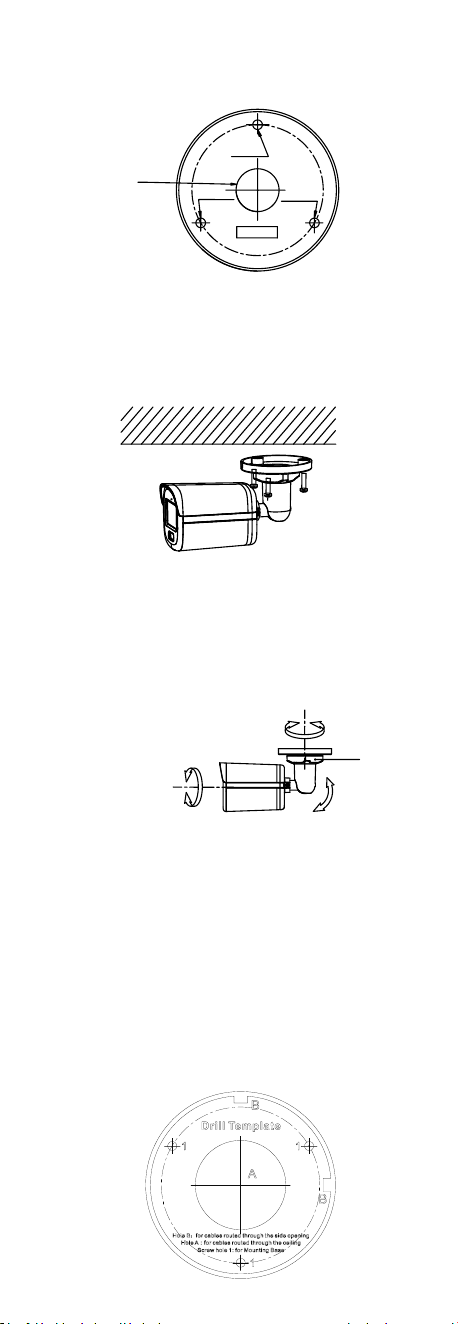
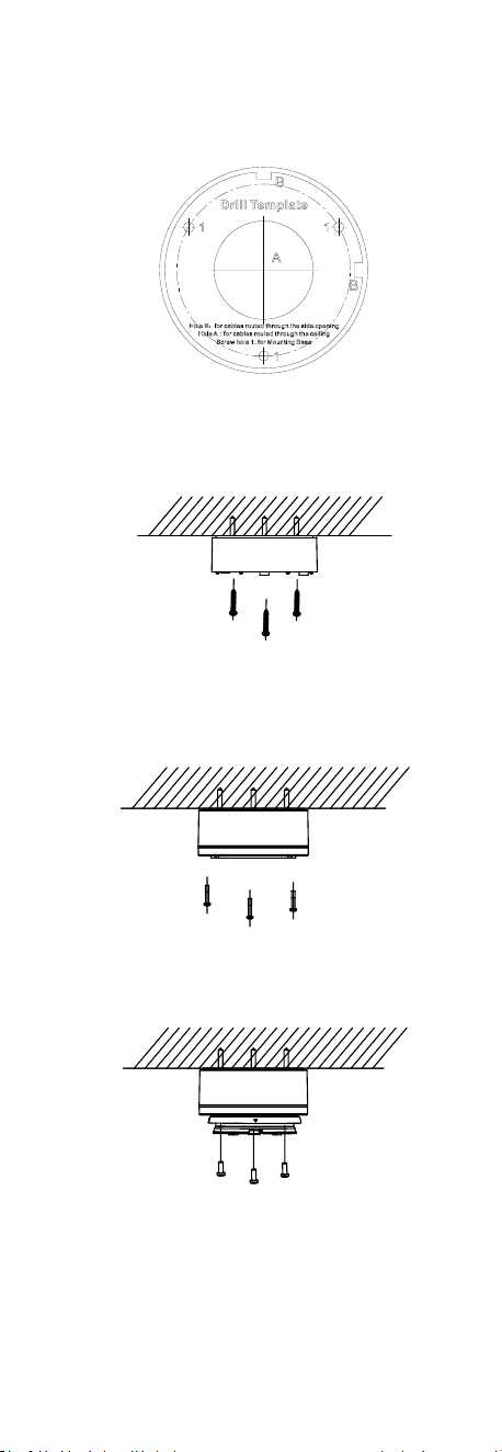
1. Paste the drill template (supplied) to the place where
you want to install the camera.
2. (Optional) For cement ceiling, drill the screw holes
with a 5.5 mm drill and insert the supplied wall plugs.
Screw
Hole
Screw
Hole
Screw
Hole
template
Cable
Hole
Figure 2-1 Drill Template
3. (Optional) Drill the cable hole, when the cables are
routed through the ceiling.
4. Align the screw holes in the bracket to the ceiling, and
secure the camera with three PA4 × 25 screws
(supplied).
Figure 2-2 Secure Camera to Ceiling
5. Connect the power cord and video cable.
6. Power on the camera to check whether the image on
the monitor is gotten from the optimum angle. If not,
turn the trim ring counterclockwise to loosen it and
adjust the positions according to the figure below.
Rotation Position
[0° to 360°]
Tilt Position
[0° to 90°]
Pan Position
[0° to 360°]
Trim Ring
Figure 2-3 3-Axis Adjustment
7. Turn the trim ring clockwise to lock the positions.
2.1.2 Ceiling/Wall Mounting with Junction Box
Before you start:
You need to purchase a junction box in advance.
Ceiling mounting and wall mounting are similar.
Following steps take wall mounting as an example.
Steps:
1. Paste the drill template for junction box to the place
where you want to install the camera.
2. (Optional) For cement wall, drill the screw holes with
a 5.5 mm drill and insert the supplied wall plugs.
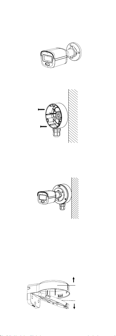
Figure 2-4 Drill Template for Junction Box
3. (Optional) Drill the cable hole, when the cables are
routed through the wall.
4. Take apart the junction box.
5. Align the screw holes of the camera with those on the
junction box cover. Attach the camera to the junction
box cover with three PM4 × 10 screws.
Figure 2-5 Attach Camera to Junction Box Cover
6. Secure the junction box body on the wall with three
PA4 × 25 screws (supplied).
Figure 2-6 Secure Junction Box on Wall
7. Route the cables through the bottom cable hole or
side cable hole of the junction box and connect the
cables.
8. Fix the junction box cover on its body with three PM3
× 16 L6 screws that come with the junction box.
Figure 2-7 Fix Junction Box Cover on Its
Body
9. Repeat steps 6 to 7 of 2.1.1 Ceiling/Wall Mounting to
adjust the angle and finish the installation.
2.1.3 Wall Mounting with Wall Mount
Before you start:
You need to purchase a wall mount in advance.
Steps:
1. Take apart the wall mount.
Main Body
Cover
Figure 2-8 Take Apart Wall Mount
2. Paste the drill template (supplied) to the place where
you want to install the camera.
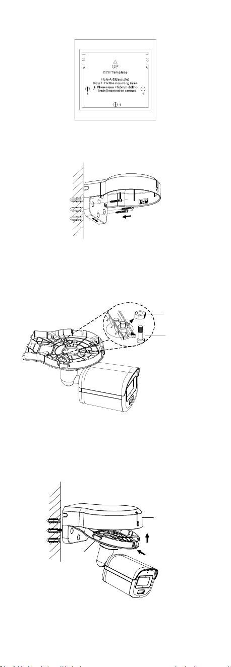
3. Drill the screw holes with a 5.5 mm drill and insert the
supplied wall plugs.
Figure 2-9 Drill Template for Wall Mount
4. Attach the main body of the wall mount to the wall
and secure it with three PA4 × 25 screws (supplied).
Figure 2-10 Secure Main Body to Wall
5. (Optional) Drill the cable hole, when the cables are
routed through the wall.
6. Secure the camera to the cover of the wall mount with
three PM4 × 13 screws and three M4 screws.
PM4 × 13 screw
M4 screw
Figure 2-11 Secure Camera to Wall Mount Cover
7. Route the cables through the cable hole of the wall
mount and connect the cables.
8. Insert one end of the wall mount cover diagonally into
the wall mount body, and then snap the other end of
the cover upward on the body.
Step 1
Step 2
Main Body
Cover
Figure 2-12 Secure Cover to Body
9. Lock the cover to the body with one PA3 × 8 screw.
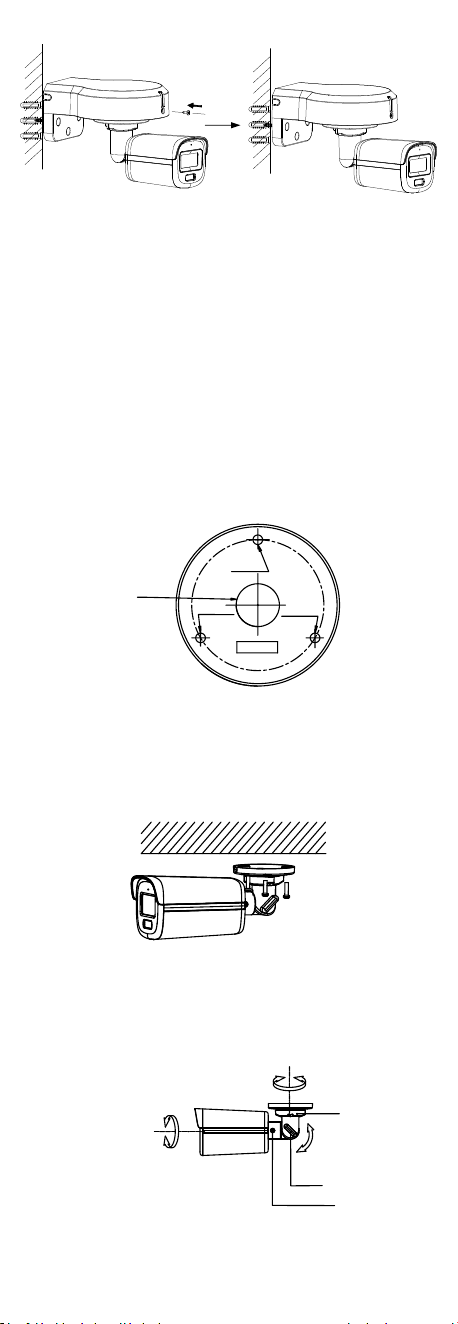
Figure 2-13 Lock Cover to Body
10. Repeat steps 6 to 7 of 2.1.1 Ceiling/Wall Mounting to
adjust the angle and finish the installation.
2.2 Installation of Type II Camera
2.2.1 Ceiling/Wall Mounting
Before you start:
Ceiling mounting and wall mounting are similar. Following
steps take ceiling mounting as an example.
Steps:
1. Paste the drill template (supplied) to the place where
you want to install the camera.
2. (Optional) For cement ceiling, drill the screw holes
with a 5.5 mm drill and insert the supplied wall plugs.
Screw
Hole
Screw
Hole
Screw
Hole
template
Cable
Hole
Figure 2-14 Drill Template
3. (Optional) Drill the cable hole, when the cables are
routed through the ceiling.
4. Align the screw holes in the bracket to the ceiling, and
secure the camera with three PA4 × 25 screws
(supplied).
Figure 2-15 Secure Camera to Ceiling
5. Connect the power cord and video cable.
6. Power on the camera to check whether the image on
the monitor is gotten from the optimum angle. If not,
adjust the camera according to the figure below.
Rotation Position
[0° to 360°]
Tilt Position
[0° to 180°]
Pan Position
[0° to 360°]
Trim Ring
Screw
Thumbscrew
Figure 2-16 3-Axis Adjustment
1). Loosen the trim ring to adjust the pan position [0°
to 360°].
2). Loosen the thumbscrew to adjust the tilt position
[0° to 180°].
3). Loosen the screw to adjust the rotation position
[0° to 360°].
7. Tighten the trim ring and screws to finish the
installation.
2.2.2 Ceiling/Wall Mounting With Junction Box
For installation with junction box, refers to 2.1.2
Ceiling/Wall Mounting with Junction Box.
2.2.3 Wall Mounting With Wall Mount
For installation with wall mount, refers to 2.1.3 Wall
Mounting with Wall Mount.
2.3 Installation of Type III Camera
2.3.1 Ceiling/Wall Mounting
Steps:
1. Paste the drill template (supplied) to the place where
you want to install the camera.
2. (Optional) For cement ceiling, drill the screw holes
with a 5.5 mm drill and insert the supplied wall plugs.
Figure 2-17 Drill Template
3. Attach the gang box to the ceiling and secure it with
three PA4 × 25 screws (supplied).
Figure 2-18 Attach Gang Box to Ceiling
4. Fit the camera onto the gang box.
Figure 2-19 Fit Camera onto Gang Box
5. Turn the camera clockwise until it snaps into the gang
box.
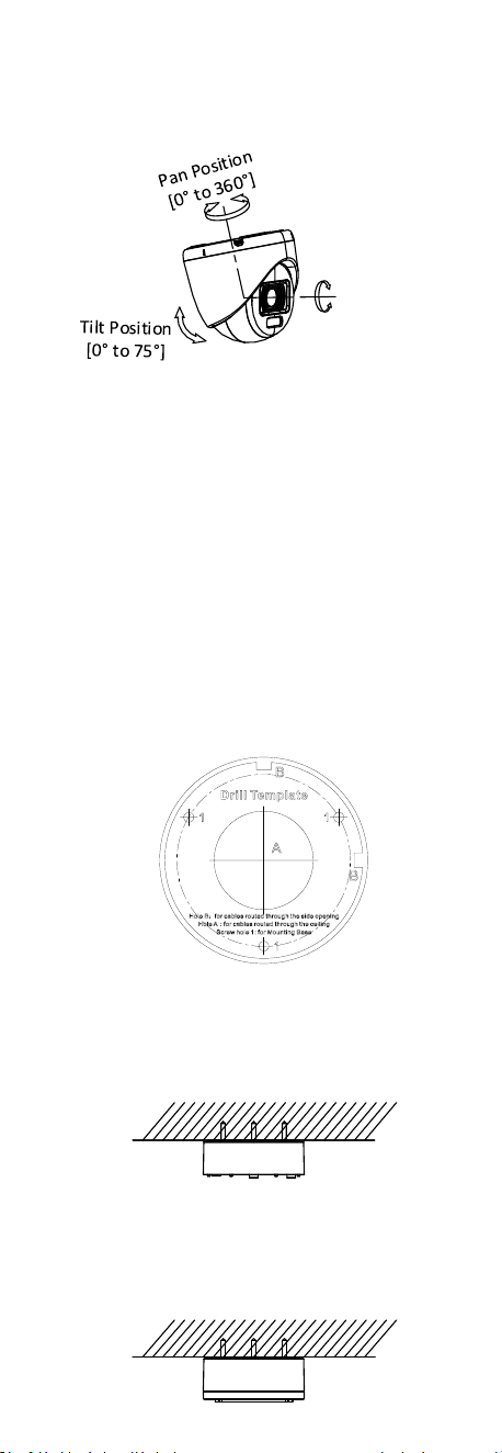
Figure 2-20 Snap Camera into Gang Box
6. Connect the power cord and video cable.
7. Power on the camera to check whether the image on
the monitor is gotten from the optimum angle. If not,
adjust the camera according to the figure below.
Rotation Postion
[0° to 360°]
Figure 2-21 3-Axis Adjustment
1). Rotate the enclosure to adjust the pan position [0°
to 360°].
2). Move the main body up and down to adjust the
tilt position [0° to 75°].
3). Rotate the main body to adjust the rotation
position [0° to 360°].
2.3.2 Ceiling/Wall Mounting with Junction Box
Before you start:
You need to purchase a junction box in advance.
Steps:
1. Loosen screws to take apart the junction box.
2. Paste the drill template for junction box to the place
where you want to install the camera.
3. (Optional) For cement ceiling, drill the screw holes
with a 5.5 mm drill and insert the supplied wall plugs.
Figure 2-22 Drill Template for Junction Box
4. (Optional) Drill the cable hole, when the cables are
routed through the ceiling.
5. Secure the junction box body on the ceiling with three
PA4 × 25 screws that come with the junction box.
Figure 2-23 Secure Junction Box Body
6. Route the cables through the bottom cable hole or
the side cable hole of the junction box.
7. Combine the junction box cover with its body and
secure it with three PM3 × 13 screws.

Figure 2-24 Combine Junction Box Cover and Body
8. Fix the gang box onto the junction box cover with PA4
× 10 screws that come with the junction box.
9. Connect the power cord and video cable and put the
cables back into the junction box.
10. Press the camera base to the gang box. Turn the
camera clockwise until it snaps into the gang box.
11. Refer to step 6 to 7 of 2.3.1 Ceiling/Wall Mounting to
adjust the angle and finish the installation.
Figure 2-25 Finish Installation
2.3.3 Wall Mounting with Wall Mount
Before you start:
You need to purchase a wall mount in advance.
Type I Wall Mount
Steps:
1. Drill Ø10 mm screw holes in the wall where you want
to install the wall mount.
2. Use M6 × 75 metal expansion bolts to fix the wall
mount onto the wall.
Figure 2-26 Fix Wall Mount
3. Use PM4 × 10 screws to fix the gang box onto the wall
mount.
Figure 2-27 Fix Gang Box
4. Repeat the step 4 to 7 of 2.3.1 Ceiling/Wall Mounting
to adjust the angle and finish the installation.
Figure 2-28 Finish Installation
Type II Wall Mount
Steps:
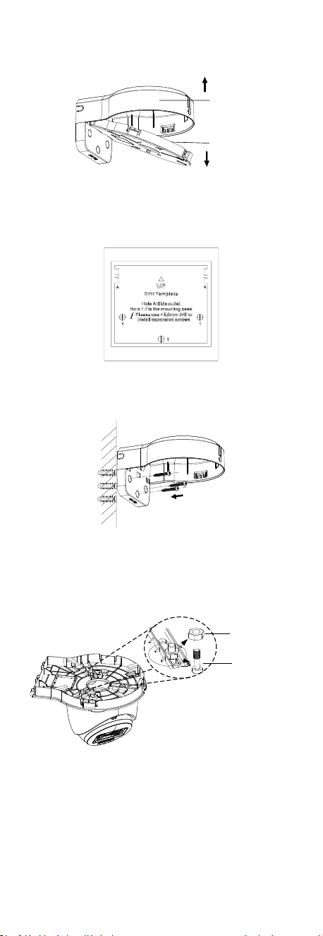
1. Take apart the wall mount.
Main Body
Cover
Figure 2-29 Take Apart Wall Mount
2. Paste the drill template (supplied) to the place where
you want to install the camera.
3. Drill the screw holes with a 5.5 mm drill and insert the
supplied wall plugs.
Figure 2-30 Drill Template for Wall Mount
4. Attach the main body of the wall mount to the wall
and secure it with three PA4 × 25 screws (supplied).
Figure 2-31 Secure Main Body to Wall
5. (Optional) Drill the cable hole, when the cables are
routed through the wall.
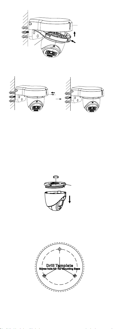
6. Secure the camera to the cover of the wall mount with
three PM4 × 13 screws and three M4 screws.
PM 4 × 13 screw
M 4 screw
Figure 2-32 Secure Camera to Wall Mount Cover
7. Route the cables through the cable hole of the wall
mount and connect the cables.
8. Insert one end of the wall mount cover diagonally into
the wall mount body, and then snap the other end of
the cover upward on the body.
Step 1
Step 2
Main Body
Cover
Figure 2-33 Secure Cover to Body
9. Lock the cover to the body with one PA3 × 8 screw.
Figure 2-34 Lock Cover to Body
10. Repeat steps 6 to 7 of 2.3.1 Ceiling/Wall Mounting to
adjust the angle and finish the installation.
2.4 Installation of Type IV Camera
2.4.1 Ceiling/Wall Mounting
Steps:
1. Loosen the set screw.
2. Rotate the camera to align the triangle mark with the
screw hole, and dissemble the camera.
Triangle
Mark
Figure 2-35 Dissemble Camera
3. Paste the drill template (supplied) to the place where
you want to install the camera.
4. (Optional) For cement ceiling, drill the screw holes
with a 5.5 mm drill and insert the supplied wall plugs.
Figure 2-36 Drill Template
5. Use three PA4 × 25 screws (supplied) to secure the
base to the ceiling.
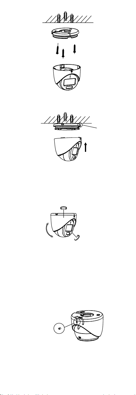
Figure 2-37 Secure Base to Ceiling
6. Align the screw hole with the triangle mark to install
the camera back to the base and secure it.
Triangle
Mark
Figure 2-38 Install Camera Back
7. Connect the power cord and video cable.
8. Power on the camera to check whether the image on
the monitor is gotten from the optimum angle. If not,
adjust the camera according to the figure below.
Rotation Position
[0° to 360°]
Tilt Position
[0° to 75°]
Pan Position
[0°to 360°]
Figure 2-39 3-Axis Adjustment
1). Rotate the enclosure to adjust the pan position [0°
to 360°].
2). Move the main body up and down to adjust the
tilt position [0° to 75°].
3). Rotate the main body to adjust the rotation
position [0° to 360°].
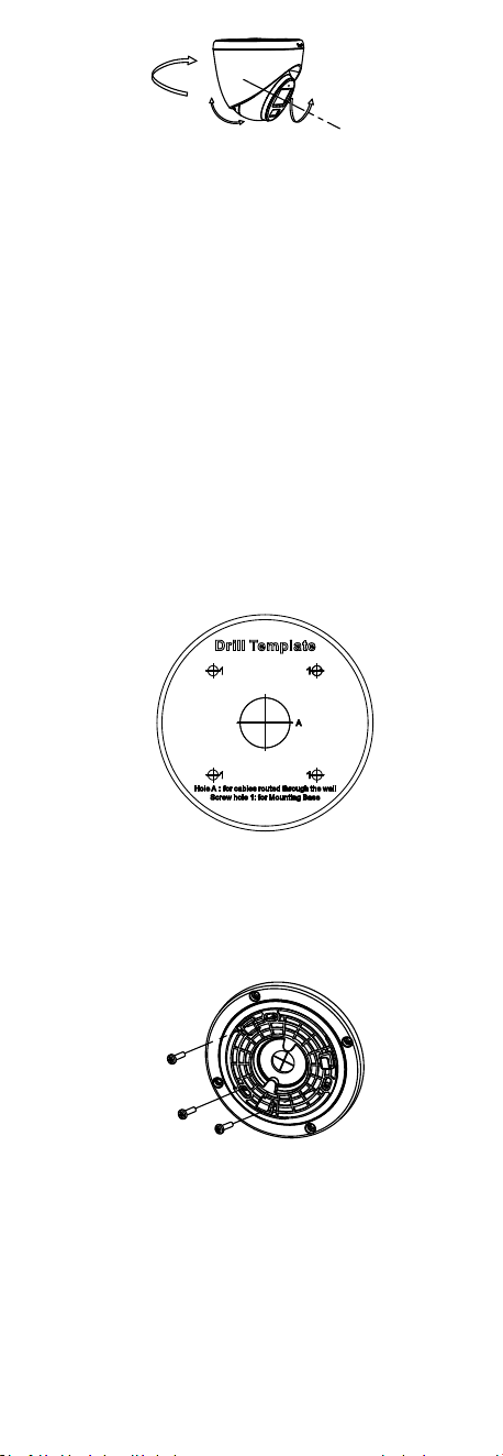
9. Tighten the set screw to finish the installation.
Note:
If you need to adjust the angle after installation,
loosen the set screw first and then repeat step 8 to 9.
Set Screw
Figure 2-40 Loosen the Set Screw
2.4.2 Ceiling/Wall Mounting with Junction Box
Before you start:
You need to purchase a junction box in advance.
Steps:
1. Loosen screws to take apart the junction box.
2. Paste the drill template for junction box to the place
where you want to install the camera.
3. (Optional) For cement ceiling, drill the screw holes
with a 5.5 mm drill and insert the supplied wall plugs.
Figure 2-41 Drill Template for Junction Box
4. (Optional) Drill the cable hole, when the cables are
routed through the ceiling.
5. Secure the junction box body on the ceiling with three
PA4 × 25 screws that come with the junction box.
Figure 2-42 Secure Junction Box Body
6. Route the cables through the bottom cable hole or
the side cable hole of the junction box.
7. Combine the junction box cover with its body and
secure it with three PM3 × 13 screws.
Figure 2-43 Combine Junction Box Cover and Body
8. Fix the base onto the junction box cover with three
M4 × 10 screws.
Figure 2-44 Fix Base
9. Connect the power cord and video cable and put the
cables back into the junction box.
10. Repeat the step 6, 8, and 9 of 2.4.1 Ceiling/Wall
Mounting to adjust the angle and finish the
installation.
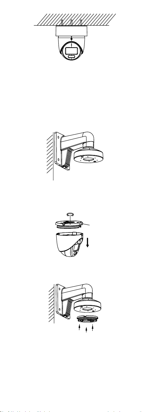
Figure 2-45 Finish Installation
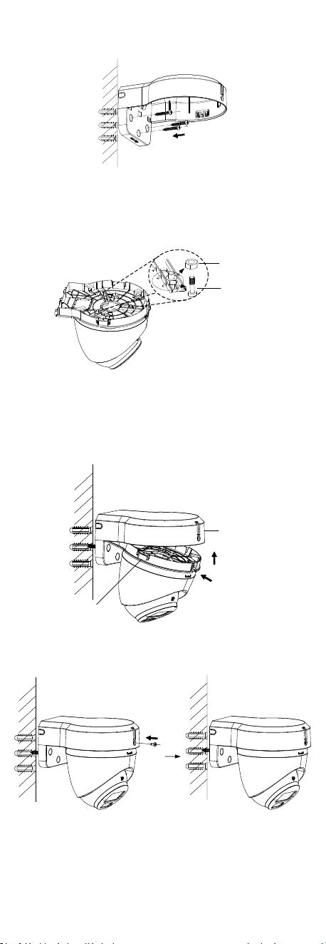
2.4.3 Wall Mounting with Wall Mount
Before you start:
You need to purchase a wall mount in advance.
Steps:
1. Drill Ø10 mm screw holes in the wall where you want
to install the wall mount.
2. Use four M6 expansion bolts to fix the wall mount
onto the wall.
Figure 2-46 Fix Wall Mount
3. Loosen the set screw.
4. Rotate the camera to align the triangle mark with the
screw hole, and disassemble the camera.
Triangle
Mark
Figure 2-47 Dissemble Camera
5. Use M4 × 10 screws to fix the base onto the wall
mount.
Figure 2-48 Fix the Base onto the Wall Mount
6. Repeat steps 6 to 9 of 2.4.1 Ceiling/Wall Mounting to
adjust the angle and finish the installation.
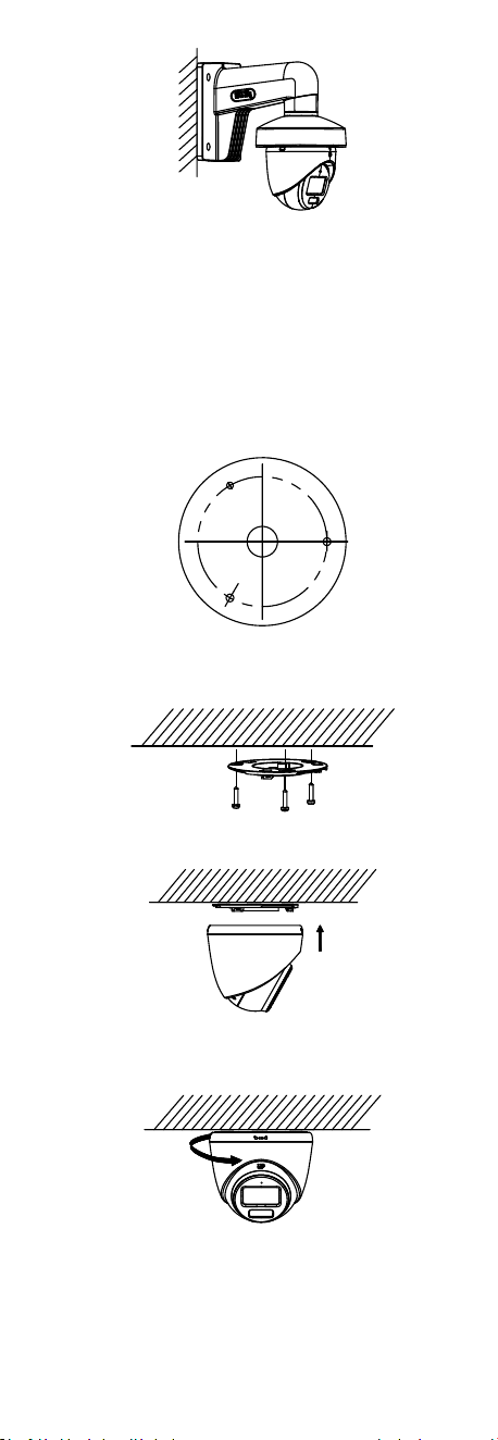
Figure 2-49 Finish Installation
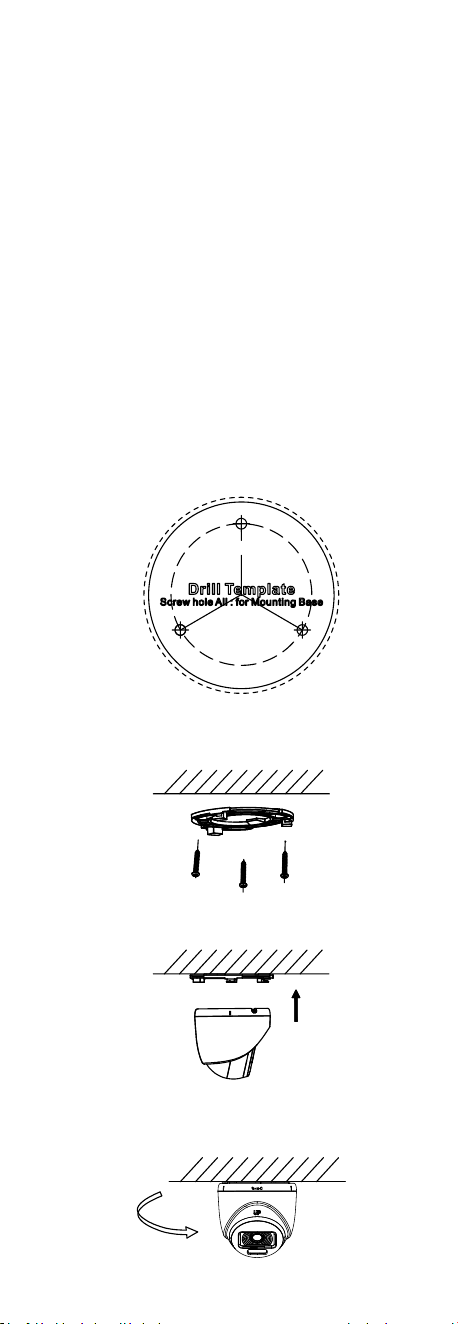
2.5 Installation of Type V Camera
2.5.1 Ceiling/Wall Mounting
Steps:
1. Paste the drill template (supplied) to the place where
you want to install the camera.
2. (Optional) For cement ceiling, drill the screw holes
with a 5.5 mm drill and insert the supplied wall plugs.
Figure 2-50 Drill Template
3. Attach the gang box to the ceiling and secure it with
three PA4 × 25 screws (supplied).
Figure 2-51 Attach Gang Box to Ceiling
4. Fit the camera onto the gang box.
Figure 2-52 Fit Camera
5. Turn the camera clockwise until it snaps into the gang
box.
Figure 2-53 Snap Camera into Gang Box
6. Connect the power cord and video cable.
7. Power on the camera to check whether the image on
the monitor is gotten from the optimum angle. If not,
adjust the camera according to the figure below.
Rotation Position
[0° to 360°]
Pan Position
[0° to 360°]
Tilt Position
[0° to 75°]
Figure 2-54 3-Axis Adjustment
1). Rotate the enclosure to adjust the pan position [0°
to 360°].
2). Move the main body up and down to adjust the
tilt position [0° to 75°].
3). Rotate the main body to adjust the rotation
position [0° to 360°].
2.5.2 Ceiling Mounting with Junction Box/Inclined
Ceiling Mount
Before you start:
You need to purchase a junction box or inclined ceiling
mount in advance.
Ceiling mounting with junction box and inclined ceiling
mount are similar. Following steps take junction box as
an example.
Steps:
1. Paste the drill template for junction box to the place
where you want to install the camera.
2. (Optional) For cement ceiling, drill the screw holes
with a 5.5 mm drill and insert the supplied wall plugs.
Figure 2-55 Drill Template
3. (Optional) Drill the cable hole, when the cables are
routed through the wall.
4. Take apart the junction box.
5. Install the gang box to the junction box cover with
three PM4 screws.
Figure 2-56 Install Gang Box to Junction Box Cover
6. Fit the camera onto the gang box.
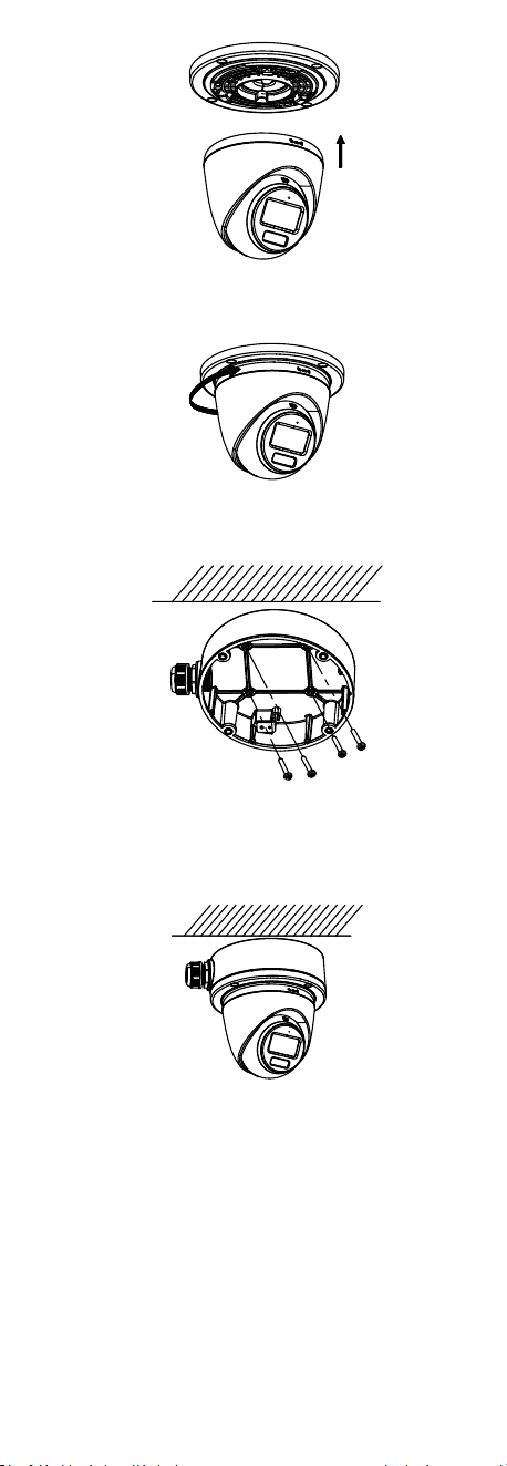
Figure 2-57 Fit Camera
7. Turn the camera clockwise until it snaps into the gang
box.
Figure 2-58 Snap Camera into Gang Box
8. Secure the junction box body on the ceiling with four
PA4 × 25 screws.
Figure 2-59 Secure Junction Box Body
9. Route the cables through the bottom cable hole or
the side cable hole of the junction box and connect
the cables.
10. Combine the junction box cover with its body.
Figure 2-60 Combine Junction Box Cover with Body
11. Refer to step 6 to 7 of 2.5.1 Ceiling/Wall Mounting to
adjust the angle and finish the installation.
2.5.3 Wall Mounting with Wall Mount
Before you start:
You need to purchase a wall mount in advance.
Type I Wall Mount
Steps:
1. Drill Ø10 mm screw holes in the wall where you want
to install the wall mount.
2. Use four M6 expansion bolts to fix the wall mount
onto the wall.
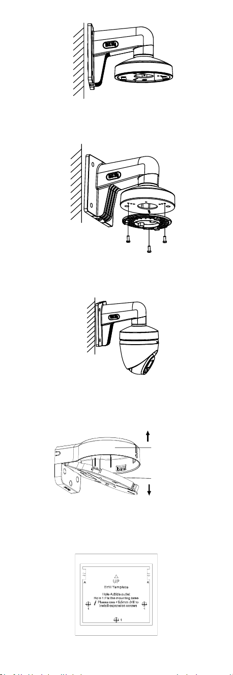
Figure 2-61 Fix Wall Mount
3. Use three PM4 × 10 screws to fix the gang box onto
the wall mount.
Figure 2-62 Fix Gang Box
4. Repeat the step 4 to 7 of 2.5.1 Ceiling/Wall Mounting
to adjust the angle and finish the installation.
Figure 2-63 Finish Installation
Type I Wall Mount
1. Take apart the wall mount.
Main Body
Cover
Figure 2-64 Take Apart Wall Mount
2. Paste the drill template (supplied) to the place where
you want to install the camera.
3. Drill the screw holes with a 5.5 mm drill and insert the
supplied wall plugs.
Figure 2-65 Drill Template for Wall Mount
4. Attach the main body of the wall mount to the wall
and secure it with three PA4 × 25 screws (supplied).
Figure 2-66 Secure Main Body to Wall
5. (Optional) Drill the cable hole, when the cables are
routed through the wall.
6. Secure the camera to the cover of the wall mount with
three PM4 × 13 screws and three M4 screws.
PM 4 × 13 screw
M 4 screw
Figure 2-67 Secure Camera to Wall Mount Cover
7. Route the cables through the cable hole of the wall
mount and connect the cables.
8. Insert one end of the wall mount cover diagonally into
the wall mount body, and then snap the other end of
the cover upward on the body.
Step 1
Step 2
Main Body
Cover
Figure 2-68 Secure Cover to Body
9. Lock the cover to the body with one PA3 × 8 screw.
Figure 2-69 Lock cover to Body
10. Repeat steps 6 to 7 of 2.5.1 Ceiling/Wall Mounting to
adjust the angle and finish the installation.
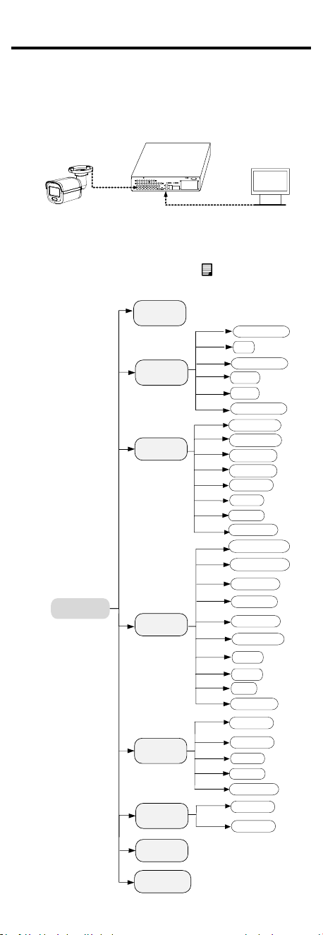
3 Menu Description
Please follow the steps below to call the menu.
Note:
The actual display may vary with your camera model.
Steps:
1. Connect the camera with the TVI DVR and the
monitor, as shown in figure 3-1.
Camera
TVI DVR
Monitor
Figure 3-1 Connection
2. Power on the camera, TVI DVR, and monitor to view
the image on the monitor.
3. Click PTZ Control to enter the PTZ Control interface.
4. Call the camera menu by clicking button or calling
preset No. 95.
EXPOSURE
EXPOSURE MODE
MAIN MENU
VIDEO
SETTINGS
EXIT
SAVE & EXIT
AGC
BACK
EXIT
CONTRAST
SHARPNESS
SATURATION
DNR
BACK
VIDEO
FORMAT
AUDIO
SETTINGS
SAVE & EXIT
WHITE BALANCE
BRIGHTNESS
EXIT
SAVE & EXIT
IMAGE MODE
ANTI- BANDING
FACTORY
DEFAULT
AUDIO
BACK
EXIT
SAVE
&
VOLUME
EXIT
CANCEL
CONFIRM
LIGHTING
LIGHTING MODE
BACK
EXIT
SAVE & EXIT
THRESHOLD
LEVEL
SETTINGS
IR/WHITE LIGHT
SMART IR

Figure 3-2 Main Menu Overview
5. Click the direction buttons to control the camera.
1). Click up/down direction buttons to select menu
options.
2). Click Iris + to confirm the selection.
3). Click left/right direction buttons to adjust the
value of the selected option.
3.1 VIDEO FORMAT
You can set the video format to 2MP@25 fps, 2MP@30
fps, PAL, or NTSC.
3.2 EXPOSURE
EXPOSURE MODE
You can set the EXPOSURE MODE to GLOBAL, BLC, HLC,
or DWDR.
GLOBAL
GLOBAL refers to the normal exposure mode which
adjusts lighting distribution, variations, and non-standard
processing.
BLC (Backlight Compensation)
BLC (Backlight Compensation) compensates light to the
object in the front to make it clear, but this may cause
over-exposure of the background where the light is
strong.
HLC (Highlight Compensation)
HLC stands for highlight compensation. The camera
detects strong spots (over-exposure portion of image)
and reduces the brightness of strong spots to improve the
overall images.
DWDR (Digital Wide Dynamic Range)
Digital wide dynamic range gives the camera the ability to
view dark areas of given image as well as extremely
lighted portions of the image or areas of high contrast.
AGC (Auto Gain Control)
It optimizes the clarity of the image in poor light
conditions. The AGC level can be set to HIGH, MEDIUM,
or LOW.
Note:
The noise will be amplified when setting the AGC level.
ANTI-BANDING
ANTI-BANDING is a camera setting that prevents the
appearance of horizontal lines (banding) when
photographing images in low frequency light and high
brightness environments.
3.3 LIGHTING SETTINGS
I LIGHTING MODE
IR and WHITE LIGHT are available.
IR
IR LIGHT
You can turn on/off the IR LIGHT to meet the
requirements of different circumstances.
SMART IR
The Smart IR function is used to adjust the light to its
most suitable intensity, and prevent the image from over
exposure.
D N Threshold (Day to Night Threshold)
Day to Night Threshold is used to control the sensitivity
of switching the day mode to the night mode. You can set
the value from 1 to 9. The larger the value is, the more
sensitive the camera is.
N D Threshold (Night to Day Threshold)

Night to Day Threshold is used to control the sensitivity
of switching the night mode to the day mode. You can set
the value from 1 to 9. The larger the value is, the more
sensitive the camera is.
WHITE LIGHT
Under the WHITE LIGHT sub-menu, you can set the mode
to OFF or AUTO.
OFF: Set it to OFF to give up this function.
AUTO: You can set THRESHOLD and LEVEL in this section.
THRESHOLD
The higher the threshold is, the more sensitive the device
is to dark environment.
LEVEL
You can adjust the maximum brightness of supplement
light.
3.4 VIDEO SETTINGS
Move the cursor to VIDEO SETTINGS and click Iris+ to
enter the submenu. IMAGE MODE, WHITE BALANCE,
BRIGHTNESS, CONTRAST, SHARPNESS, SATURATION, and
DNR are adjustable.
VIDEO SETTINGS
IMAGE MODE STD
WHITE BALANCE
BRIGHTNESS
CONTRAST
SHARPNESS
SATURATION
3DNR
BACK
EXIT
SAVE & EXIT
5
5
5
5
5
Figure 3-3 VIDEO SETTINGS
IMAGE MODE
IMAGE MODE is used to adjust the image saturation, and
you can set it to STD (Standard), HIGH-SAT (High
Saturation), or HIGHLIGHT (better indoor facial details).
WHITE BALANCE
White balance, the white rendition function of the
camera, is to adjust the color temperature according to
the environment. It can remove unrealistic color casts in
the image. You can set WHITE BALANCE mode to AUTO or
MANUAL.
AUTO
Under AUTO mode, white balance is being adjusted
automatically according to the color temperature of the
scene illumination.
MANUAL
You can adjust the R-GAIN and B-GAIN value to correct
colors manually.
WHITE BALANCE
MODE
R-GAIN
B-GAIN
BACK
EXIT
SAVE&EXIT
MANUAL
5
5

Figure 3-4 WHITE BALANCE
BRIGHTNESS
Brightness refers to the brightness of the image. You can
set the brightness value from 1 to 9 to darken or brighten
the image. The greater the value is, the brighter the
image is.
CONTRAST
This feature enhances the difference in color and light
between parts of an image.
SHARPNESS
Sharpness determines the amount of detail an imaging
system can reproduce.
SATURATION
Saturation is the proportion of pure chromatic color in the
total color sensation. Adjust this feature to change the
saturation of the color.
DNR
DNR refers to digital noise reduction. This function
reduces noise in video stream.
3.5 AUDIO SETTINGS
Under the AUTO SETTINGS sub-menu, you can set the
mode to ON or OFF. Adjust the VOLUME value to turn
up/down the volume.
AUDIO SETTINGS
AUDIO
VOLUME
BACK
EXIT
SAVE&EXIT
ON
5
Figure 3-5 AUTO SETTINGS
3.6 FACTORY DEFAULT
Click CANCEL to back to the main menu.
Click CONFIRM to reset all the settings to factory defaults.
3.7 EXIT
Move the cursor to EXIT and click Iris+ to exit the menu.
3.8 SAVE & EXIT
Move the cursor to SAVE & EXIT and click Iris+ to save the
settings and exit the menu.
UD31334B-A