1
WARNING
TO REDUCE THE RISK OF FIRE, ELECTRIC SHOCK, OR INJURY TO
PERSONS, OBSERVE THE FOLLOWING:
1. Use this unit only in the manner intended by the manufacturer. If
you have questions, contact the manufacturer at the address or
telephone number listed in the warranty.
2. Before servicing or cleaning unit, switch power off at service panel
and lock the service disconnecting means to prevent power from
being switched on accidentally. When the service disconnecting
means cannot be locked, securely fasten a prominent warning
device, such as a tag, to the service panel.
3. Installation work and electrical wiring must be done by a qualified
person(s) in accordance with all applicable codes and standards,
including fire-rated construction codes and standards.
4. Sufficient air is needed for proper combustion and exhausting of
gases through the flue (chimney) of fuel burning equipment to
prevent backdrafting. Follow the heating equipment manufacturer’s
guideline and safety standards such as those published by the
National Fire Protection Association (NFPA), and the American
Society for Heating, Refrigeration and Air Conditioning Engineers
(ASHRAE), and the local code authorities.
5. When cutting or drilling into wall or ceiling, do not damage electrical
wiring and other hidden utilities.
6. Ducted fans must always be vented to the outdoors.
7. Acceptable for use over a tub or shower when connected to a GFCI
(Ground Fault Circuit Interrupter) - protected branch circuit (ceiling
installation only).
8. This unit must be grounded.
9. Do not use this fan with any solid-state speed control device.
10. Do not use replacement parts that have not been recommended
by Broan NuTone LLC.
11. If the fan makes excessive noise or if there is unusual noise or
smells of smoke. Disconnect power supply and contact customer
service.
12. The wearing of safety glasses and gloves is recommended when
installing, maintaining or cleaning the unit to reduce the risk of
injury that could be caused by the presence of thin metal and/or
moving parts.
CAUTION
1. For general ventilating use only. Do not use to exhaust hazardous
or explosive materials and vapors.
2. Install the fan at least 8 feet (2.4 m) above the floor.
3. To avoid motor bearing damage and noisy and/or unbalanced
impellers, keep drywall spray, construction dust, etc. off power
unit.
4. DO NOT TOUCH THE HUMIDITY-SENSING CIRCUIT BOARD.
Electrostatic discharge may damage the circuit board.
5. Please read specification label on product for further information
and requirements.
CLEANING & MAINTENANCE
TO CLEAN THE GRILLE: Remove the grille and grille trim. Plastic
parts can be cleaned with mild detergent, such as dishwashing
liquid. Dry with a soft cloth. DO NOT USE ABRASIVE CLOTH, STEEL
WOOL PADS OR SCOURING POWDERS.
TO CLEAN INTERIOR OF THE UNIT: Once the grille and grille trim
are removed, gently vacuum interior of the unit with the dusting
brush attachment.
READ AND SAVE THESE INSTRUCTIONS
TO CLEAN THE SENSOR: Remove the grille and grille trim. Use a
dry dustcloth, clean toothbrush or lightly vacuum to clean sensor
and grille. DO NOT USE ABRASIVE CLOTH, STEEL WOOL PADS OR
SCOURING POWDERS. DO NOT USE cleaning sprays, solvents or
water on or near sensor!
The motor is permanently lubricated and never needs oiling. If the
motor bearings are making excessive or unusual noises, replace the
blower assembly (includes motor and impeller).
OPERATION
Use an on/off switch to operate the fan and sensor. The fan and
sensor can be operated separately if an appropriate 2-function wall
control is used.
Refer to Broan-NuTone catalog for a complete line of accessories/
controls to effectively adapt these fans to your requirements.
SENSOR OPERATION
To activate the humidity sensor, turn the humidity switch ON.
The fan will run automatically when the set Humidity condition
is met, and stop automatically when the timer condition is met.
The Humidity Sensor may occasionally turn the fan ON when
environmental conditions change.
BES8 Roomside Series
Humidity Sensing Fan
For Warranty Statement, Service Parts, Technical Support,
or to Register your product, please visit our website or call:
In the United States - Broan-NuTone.com 800-558-1711.
In Canada - Broan-NuTone.ca 800-567-3855.
HUMIDITY
OFF
50
90
80
70
60
100
TIME
60
50
40
30
20
0
10
%
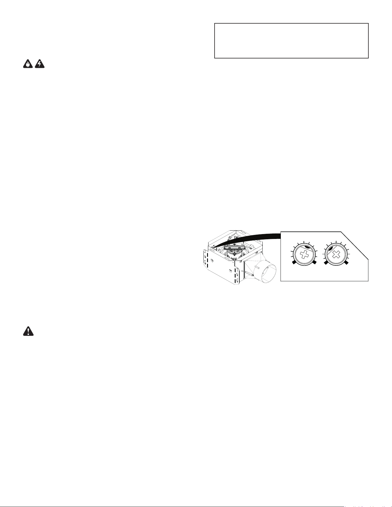
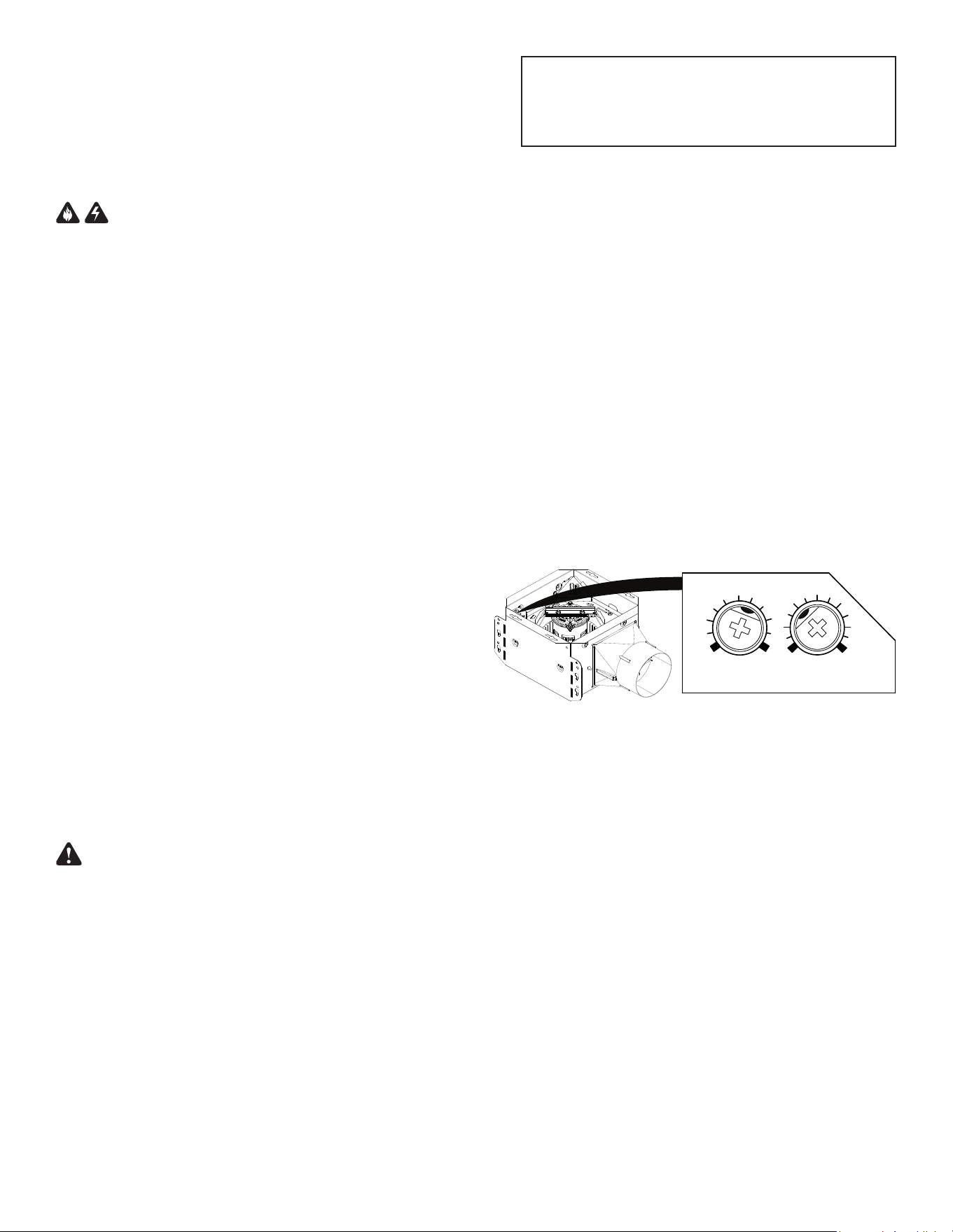
% HUMIDITY ADJUSTMENT
To adjust the % HUMIDITY:
1. Turn power off at electrical service panel.
2. Use a small screwdriver to carefully rotate %HUMIDITY control
to desired level. If fan is not responding to changing humidity
conditions, adjust towards 50%. If fan is responding too often to
changing humidity conditions, adjust towards 100%.
3. Turn power on.
4. Repeat above steps if necessary.
MINUTES ADJUSTMENT (TIMER)
This humidity-sensing fan has a timer that controls how long the
fan remains on after the humidity in the room returns to the user-
adjustable set-point.
To adjust the timer:
1. Disconnect power at electrical service panel.
2. Use a small screwdriver to carefully rotate MINUTES control to
increase or decrease time.
3. Turn power on.
4. Repeat above steps if necessary.
If fan is still not responding as desired after making adjustments,
contact Broan Technical Support.
MANUAL ON
To manually energize the fan:
- Turn the fan only switch on
or
- Cycle the Humidity switch on/off/on.

2
OPTION - To mount housing anywhere between ceiling framing:
Use optional Hanger Bar Kit (sold separately from local distributors
or website). Follow mounting instructions included with kit.
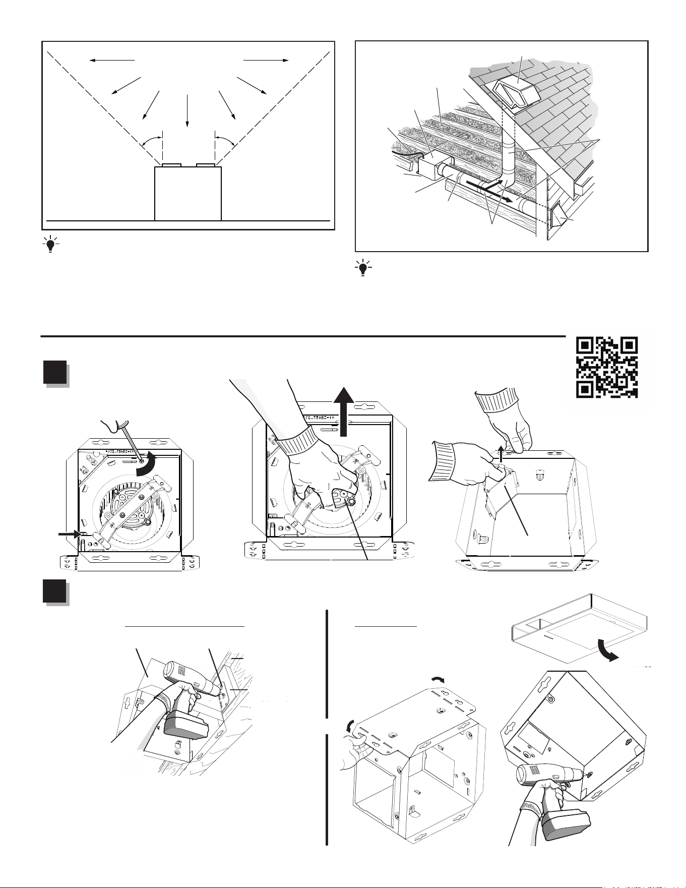
ROOF CAP* (with built-in damper)
WALL CAP*
(with built-in
damper)
4-IN. ROUND
ELBOWS*
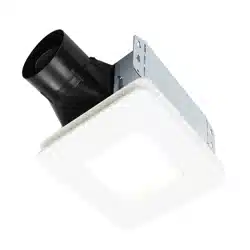
FAN
HOUSING
Seal gaps
around
housing.
Seal duct joints
with tape.
INSULATION
(Place around and
over fan housing.)
POWER
CABLE *
* Purchase separately.
OR
Keep duct
runs short.
4-IN. ROUND
DUCT*
IMPORTANT -
The ducting from this fan to the outside of the building
has a strong effect on the air flow, noise and energy use of the fan. Use
the shortest, straightest duct routing possible for best performance, and
avoid installing the fan with smaller ducts than recommended. Insulation
around the ducts can reduce energy loss and inhibit mold growth. Fans
installed with existing ducts may not achieve their rated airflow.
Cooking
Equipment
Floor
COOKING AREA
Do not install above or
inside this area.
45
o
45
o
NOT FOR USE IN
A COOKING AREA.
QUICK START GUIDE
Scan this QR code for
Installation video.
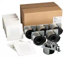
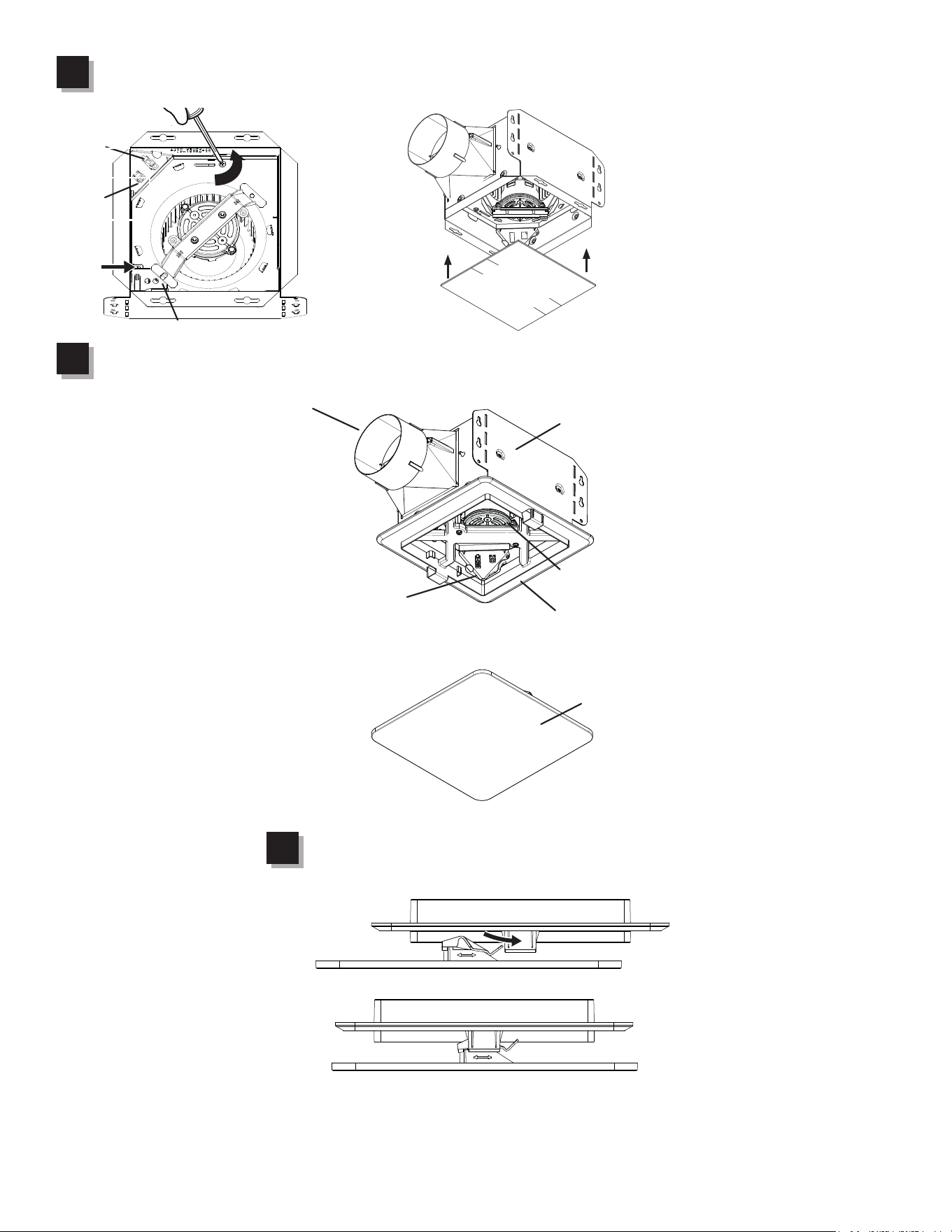
1
1
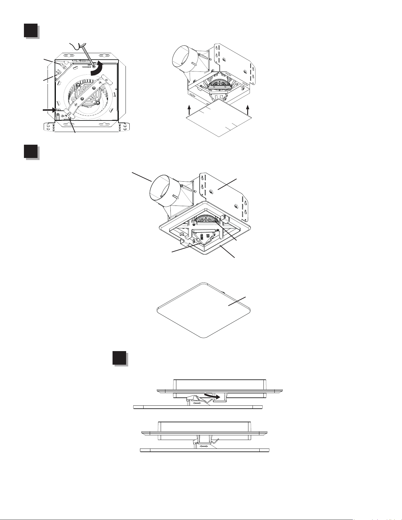
Remove from packaging. Remove blower assembly and wiring panel.
BLOWER
ASSEMBLY
WIRING
PANEL
New Construction Retrot
1
2
Mount housing.
Choose one option to mount housing to ceiling structure:
Note: If you are
installing retrofit, bend
the ears in and use the
mask from packaging to
cut opening to correct
size.
WOOD
BLOCKING
I-JOIST
or
Other options:
- Hanger bars (sold separately Model Number MHB4)
- Flange Install (see Installation video)
(IF REQUIRED)
HOUSING
MOUNTING EAR

3
1
3
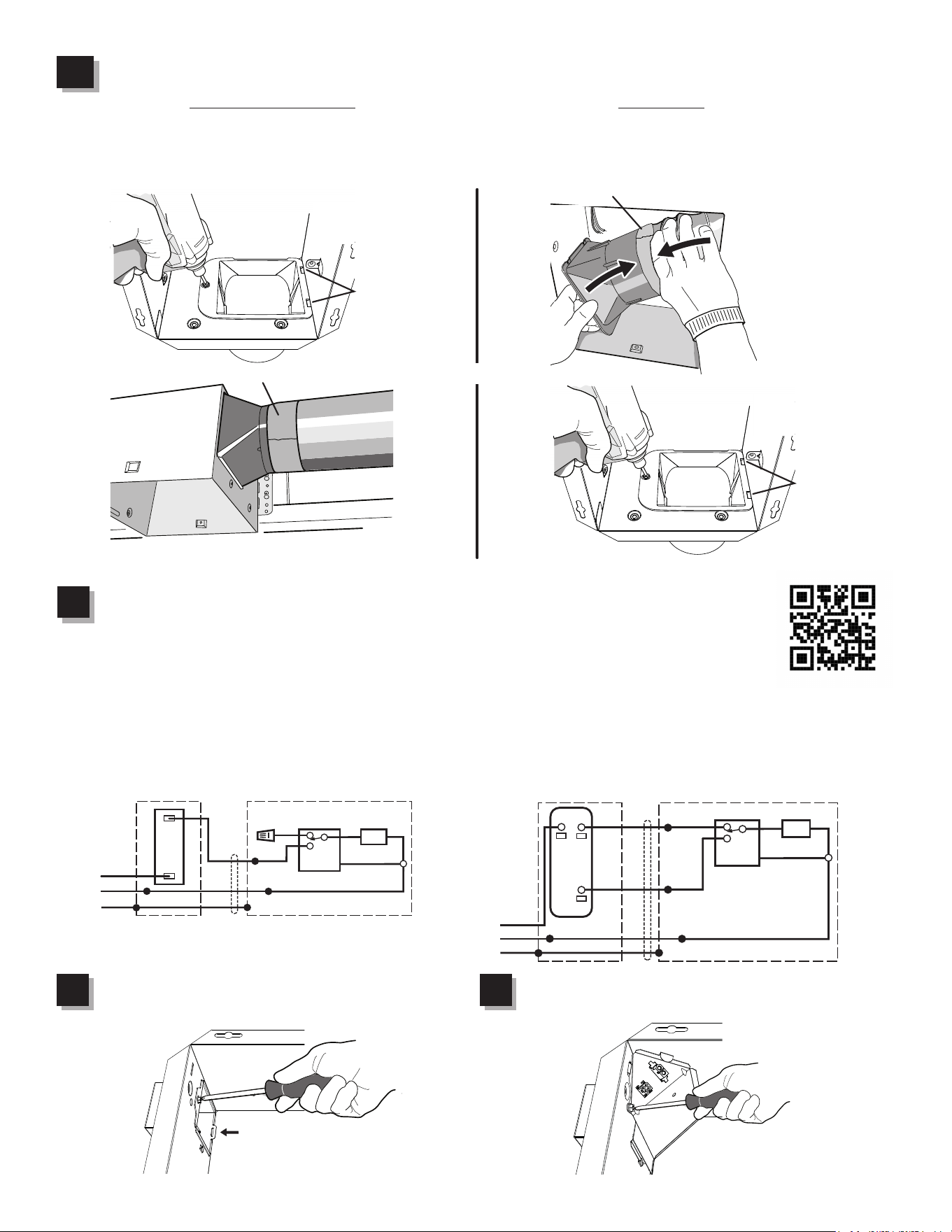
Choose one option to attach duct connector.
Pro Tip: First and last 18" of the ducting should be rigid or stretched straight for expected performance.
1
4
Connect wiring.
1
5
Attach wire enclosure by tab and screw.
TABS
FOIL TAPE
FOIL TAPE
New Construction Retrot
or
Install duct connector (use screw from parts bag
and ensure tabs engage in housing), then attach new
construction ductwork with foil tape.
TABS
Pull ductwork into housing and attach to duct connector
with foil tape, then install duct connector (use screw from
parts bag and ensure tabs engage in housing).
Re-install wiring panel and secure with screw
from parts bag.
1
6
Scan this QR code for
helpful hints.
WIRING OPTION # 1
• When switch is ON, fan will operate automatically based
on room humidity conditions.
• Turn fan ON immediately (to control odors), by cycling
switch ON/OFF/ON.
WIRING OPTION # 2
• When first switch (1) is ON, fan will operate automatically
based on room humidity conditions.
• Turn fan ON immediately (to control odors), by using
second switch (2).
ON / OFF SWITCH
(PURCHASE SEPARATELY)
ON / OFF
SWITCH
120
VAC
LINE
IN
SWITCH BOX
WHT
GRD
BLK
WHT
UNIT
GREY
BLK
WHT
GRD
WHT
BLK
WHT
BRN
HUMIDITY
CONTROL
FAN
120
VAC
LINE
IN
SWITCH BOX
WHT
GRD
WHT
UNIT
BLK
WHT
GRD
WHT
BLK
WHT
HUMIDITY
CONTROL
FAN
RED
BLK
GREY
BRN
2-FUNCTION CONTROL
(PURCHASE SEPARATELY)
COM
(1)
HUMIDITY
CONTROL
(AUTO/OFF)
(2)
FAN
(ON/OFF)
4
1115130A
Install the blower assembly and sensor with provided screws. Plug in blower. Plug in sensor.
Note: For new construction, use mask to protect blower until ceiling is finished.
1
7
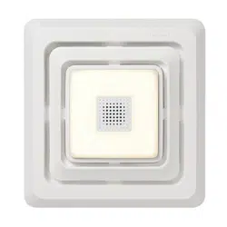
Install the grille trim with screws from parts bag.
1
8
Install the grille by sliding clips into grille trim.
DUCT CONNECTOR
HOUSING
BLOWER ASSEMBLY
WIRING PANEL
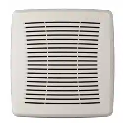
GRILLE TRIM
BES8 GRILLE
Use this mask to prevent construction dust, drywall spray
1
9
Note: Depending upon model, your grille may look different.
SENSOR
MOTOR
PLUG
SENSOR
PLUG
5
AVERTISSEMENT
OBSERVEZ LES DIRECTIVES CI-DESSOUS AFIN DE RÉDUIRE LES RISQUES
D’INCENDIE, DE CHOC ÉLECTRIQUE OU DE BLESSURES CORPORELLES :
1. N’utilisez cet appareil que de la manière prévue par le fabricant. Si vous
avez des questions, communiquez avec le fabricant à l’adresse ou au
numéro de téléphone indiqués dans la garantie.
2. Avant de procéder à l’entretien ou au nettoyage de l’appareil, coupez
l’alimentation du panneau électrique et verrouillez l’interrupteur principal
afin d’empêcher que le courant ne soit accidentellement rétabli. S’il est
impossible de verrouiller l’interrupteur principal, fixez solidement un
message d’avertissement bien visible, par exemple une étiquette, sur le
panneau électrique.
3. La pose de l’appareil et les travaux d’électricité doivent être effectués par
des personnes qualifiées conformément à la réglementation en vigueur,
notamment les normes de la construction ayant trait à la protection contre
les incendies.
4. Pour éviter les refoulements, l’apport d’air doit être suffisant pour brûler les
gaz produits par les appareils à combustion et les évacuer dans le conduit
de fumée (cheminée). Respectez les directives du fabricant de l’appareil
de chauffage et les normes de sécurité, notamment celles publiées par
la National Fire Protection Association (NFPA), l’American Society for
Heating, Refrigeration and Air Conditioning Engineers (ASHRAE) et les
codes des autorités locales.
5. Veillez à ne pas endommager le câblage électrique ou d’autres équipements
non apparents lors de la découpe ou du perçage du mur ou du plafond.
6. Les ventilateurs canalisés doivent toujours rejeter l’air à l’extérieur.
7. Cet appareil peut être installé au-dessus d’une enceinte de baignoire
ou de douche s’il est branché sur un circuit de dérivation protégé par
un disjoncteur différentiel de fuite à la terre (installation au plafond
seulement).
8. Cet appareil doit être relié à une mise à la terre.
9. Ne pas utiliser ce ventilateur avec une commande de vitesse à semi-conducteur.
10. Ne pas utiliser de pièces de rechange non recommandées par Broan
NuTone LLC.
11. Si le ventilateur produit un bruit excessif ou s’il y a un bruit, une odeur ou
de la fumée inhabituels, débrancher la source d’alimentation et contacter
le service à la clientèle.
12. Il est recommandé de porter des lunettes et des gants de sécurité lors de
l’installation, de l’entretien ou du nettoyage de cet appareil afin de réduire
le risque de blessure causée par la présence d’arête vive et/ou de pièces
mobiles.
ATTENTION
1. Pour ventilation générale uniquement. N’utilisez pas cet appareil pour
évacuer des matières ou des vapeurs dangereuses ou explosives.
2. Installer le ventilateur à au moins 2,4 m (8 pi) au-dessus du plancher.
3. Pour éviter d’endommager les roulements du moteur, de déséquilibrer les
pales ou de les rendre bruyantes, débarrassez l’appareil de la poussière
de plâtre, de construction, etc.
4. NE PAS TOUCHER LA CARTE DE CIRCUIT IMPRIMÉ DE DÉTECTION D’HUMIDITÉ.
Une décharge électrostatique pourrait endommager le circuit imprimé.
5. Veuillez lire l’étiquette de spécifications du produit pour obtenir plus de
renseignements, notamment sur les exigences.
NETTOYAGE ET ENTRETIEN
POUR NETTOYER LA GRILLE : Enlever la grille et la bordure de la grille. Les
pièces en plastique peuvent être nettoyées avec un détergent doux, tel du
liquide à vaisselle. Sécher à l’aide d’un chiffon doux. NE PAS UTILISER DE
TISSU ABRASIF, DE TAMPON À RÉCURER OU DE POUDRES À RÉCURER.
POUR NETTOYER L’INTÉRIEUR DE L’APPAREIL : Une fois la grille et la
bordure de la grille enlevées, nettoyez l’intérieur de l’appareil avec un
aspirateur muni d’une brosse à épousseter.
LISEZ CES DIRECTIVES ET
CONSERVEZ-LES
NETTOYAGE DU DÉTECTEUR : Enlever la grille et la bordure de la grille. À l’aide
d’un chiffon à épousseter, d’une brosse à dents propre ou d’un aspirateur,
nettoyer délicatement le détecteur et la grille. NE PAS UTILISER DE CHIFFONS
ABRASIFS, DE LAINE D’ACIER NI DE POUDRE À RÉCURER. NE PAS UTILISER
de nettoyant en vaporisateur, ni de solvant ni d’eau sur le détecteur ou à
proximité!
Le moteur est lubrifié en permanence et n’a pas besoin d’être huilé. Si les
roulements du moteur sont anormalement bruyants, remplacez l’ensemble
de ventilateur (incluant le moteur et la roue à ailettes).
FONCTIONNEMENT
Utiliser un interrupteur marche/arrêt pour faire fonctionner le ventilateur et
le détecteur. Il est possible de faire fonctionner le ventilateur et le détecteur
séparément si une commande murale à deux fonctions est utilisée.
Consulter le catalogue Broan-NuTone pour obtenir la ligne d’accessoires/
de commandes complète qui vous permettra d’adapter adéquatement ces
ventilateurs selon vos besoins.
FONCTIONNEMENT DU DÉTECTEUR
Pour activer le détecteur d’humidité, mettre l’interrupteur du détecteur d’humidité
en position marche. Le ventilateur fonctionnera automatiquement lorsque
le point de consigne sera atteint et s’arrêtera automatiquement à la fin de la
minuterie. Le détecteur d’humidité peut à l’occasion mettre le ventilateur en
marche lorsque les conditions ambiantes changent.
Ventilateur de série Roomside BES8
à détecteur d’humidité
Pour la déclaration de garantie, les pièces de rechange,
l’assistance technique ou pour enregistrer votre produit,
veuillez visiter notre site Web ou appeler :
Aux États-Unis : Broan-NuTone.com 800-558-1711.
Au Canada : Broan-NuTone.ca 800-567-3855.
HUMIDITY
OFF
50
90
80
70
60
100
TIME
60
50
40
30
20
0
10
%
RÉGLAGE DU % D’HUMIDITÉ
Pour ajuster le % D’HUMIDITÉ :
1. Couper le courant au panneau d’alimentation électrique.
2. À l’aide d’un petit tournevis, tourner soigneusement la commande
%HUMIDITY au niveau souhaité. Si le ventilateur ne réagit pas aux
variations d’humidité, le régler sur 50%. Si le ventilateur réagit trop
souvent aux variations d’humidité, le régler sur 100%.
3. Mettre l’alimentation sous tension.
4. Répéter les étapes ci-dessus au besoin.
RÉGLAGE DES MINUTES (MINUTERIE)
Ce ventilateur à détecteur d’humidité comporte une minuterie qui
détermine combien de temps le ventilateur reste en marche une fois
le taux d’humidité revenu au point de consigne réglé par l’utilisateur.
Pour ajuster la minuterie :
1. Couper le courant au panneau d’alimentation électrique.
2. À l’aide d’un petit tournevis, tourner soigneusement la commande
MINUTES pour augmenter ou pour diminuer la durée.
3. Mettre l’alimentation sous tension.
4. Répéter les étapes ci-dessus au besoin.
Si le ventilateur ne réagit pas tel que souhaité suite aux ajustements,
contacter l’assistance technique de Broan.
MISE EN MARCHE MANUELLE
Pour actionner manuellement le ventilateur :
- Mettre l’interrupteur du ventilateur en position marche
ou
- Effectuer un cycle avec l’interrupteur du détecteur d’humidité
(marche/arrêt/marche).
6
OPTION - Pour installer le boîtier n’importe où entre les solives du
plafond : Utilisez l’ensemble de barres de suspension offert en option
(vendu séparément chez votre distributeur local ou site Web). Suivez les
instructions accompagnant l’ensemble.
CAPUCHON DE TOIT* (avec clapet intégré)
CAPUCHON
MURAL*
(avec clapet
intégré)
10 CM (4 PO)
COUDES RONDS*
BOÎTIER DU
VENTILATEUR
Scellez
l’écart autour
du boîtier.
Scellez les joints
avec du ruban à conduit.
ISOLANT
(Le placer sur le
boîtier du ventilateur
et autour.)
CÂBLE
D’ALIMENTATION *
* Vendu séparément.
OU
Utilisez des
conduits les
plus courts
possible.
10 CM (4 PO)
CONDUIT ROND*
IMPORTANT -
Les conduits allant de ce ventilateur jusqu’à l’extérieur de
l’habitation ont une grande influence sur le débit d’air, le bruit du ventilateur et sa
consommation d’énergie. Pour obtenir le meilleur rendement, utilisez les conduits
les plus courts et les plus droits possible et évitez d’utiliser des conduits plus
petits que ceux recommandés. L’isolation des conduits peut contribuer à réduire
les pertes d’énergie et éviter la prolifération de moisissures. Les ventilateurs
installés sur d’anciens conduits pourraient ne pas produire leur débit d’air nominal.
Appareil
de cuisson
Plancher
ZONE DE CUISSON
Ne pas installer au-dessus ou
à l’intérieur de cette zone.
45
o
45
o
NE PAS INSTALLER DANS
UNE ZONE DE CUISSON.
GUIDE DE DÉMARRAGE RAPIDE
Balayer ce code QR
pour accéder à une
vidéo d’installation.
1
1
Déballer. Enlever l’assemblage du ventilateur et le panneau du câblage.
ASSEMBLAGE
DU VENTILATEUR
PANNEAU DU
CÂBLAGE
Nouvelle construction Rénovation
1
2
Installer le boîtier.
Choisir une option pour installer le boîtier à la charpente du plafond :
WOOD
BLOCKING
I-JOIST
ou
(SI REQUIS)
BOÎTIER
BRIDE DE MONTAGE
SOLIVE EN «I»
BLOC DE BOIS
Autres options :
- Support de montage (vendu séparément numéro de modèle
MHB4)
- Installation sur bride (voir la vidéo d’installation)
Note : S’il s’agit d’une installation pour
rénovation, plier les brides vers l’intérieur
et utiliser le masque qui fait partie de
l’emballage pour découper l’ouverture à la
bonne dimension.
7
1
3
Choisir une option pour raccorder le connecteur de conduit.
Conseil : La première et la dernière section de 18 po de conduit doit être rigide ou étirée pour obtenir le rendement attendu.
ERGOTS
RUBAN D’ALUMINIUM
RUBAN D’ALUMINIUM
Nouvelle construction Rénovation
ou
Installer le connecteur de conduit (utiliser la vis dans
le sac de pièces et s’assurer que les ergots s’engagent
dans le boîtier), puis raccorder le conduit de la nouvelle
construction avec du ruban d’aluminium.
ERGOTS
Tirer le conduit dans le boîtier et raccorder au connecteur
de conduit avec du ruban d’aluminium, puis installer le
connecteur de conduit (utiliser la vis dans le sac de pièces
et s’assurer que les ergots s’engagent dans le boîtier).
1
4
Effectuer les branchements.
1
5
Fixer le boîtier du câblage avec l’ergot et la vis. Réinstaller le panneau du câblage et le xer
avec la vis dans le sac de pièces.
1
6
Balayer ce code QR
pour des conseils.
OPTION DE BRANCHEMENT # 1
• Lorsque l’interrupteur est en position marche, le
ventilateur fonctionne automatiquement en fonction des
conditions d’humidité ambiante.
• Mettre immédiatement le ventilateur en marche (pour
contrôler les odeurs) en effectuant un cycle avec
l’interrupteur mural (marche/arrêt/marche).
OPTION DE BRANCHEMENT # 2
• Lorsque le premier commutateur (1) est en
position marche, le ventilateur fonctionne
automatiquement en fonction des conditions
d’humidité ambiante.
• Mettre immédiatement le ventilateur en marche
(pour contrôler les odeurs) en utilisant le
deuxième commutateur (2).
INTERRUPTEUR MARCHE/ARRÊT
(VENDU SÉPARÉMENT)
INTERRUPTEUR
MARCHE/ARRÊT
ENTRÉE
120
Vca
BLANC
FIL DE
TERRE
NOIR
BLANC
APPAREIL
GRIS
NOIR
BLANC
BLANC
NOIR
BLANC
BRUN
CONTRÔLE
D’HUMIDITÉ
VENTILATEUR
FIL DE
TERRE
BOÎTE D’INTERRUPTEUR
ENTRÉE
120
Vca
BLANC
FIL DE
TERRE
BLANC
NOIR
BLANC
BLANC
NOIR
BLANC
CONTRÔLE
D’HUMIDITÉ
VENTILATEUR
ROUGE
NOIR
GRIS
BRUN
COMMANDE À 2 FONCTIONS
(VENDUE SÉPARÉMENT)
COM
(1)
CONTRÔLE
D’HUMIDITÉ
(AUTO/ARRÊT)
(2)
VENTILATEUR
(MARCHE/ARRÊT)
FIL DE
TERRE
8
1115130A
Installer l’assemblage du ventilateur et le détecteur à l’aide des vis fournies. Brancher le ventilateur.
Brancher le détecteur. Note : Dans le cas d’une nouvelle construction, utiliser le masque pour protéger le
ventilateur jusqu’à ce que le plafond soit fini.
1
7
Installer la bordure de la grille à l’aide des vis dans le sac de pièces.
1
8
Installer la grille en glissant les clips dans la
bordure de la grille.
CONNECTEUR DE
CONDUIT
BOÎTIER
ASSEMBLAGE DU
VENTILATEUR
PANNEAU DU
CÂBLAGE
BORDURE DE LA GRILLE
GRILLE BES8
Use this mask to prevent construction dust, drywall spray
1
9
Note : La grille peut différer selon le modèle.
DÉTECTEUR
PRISE
MOTEUR
PRISE
DÉTECTEUR