Loading ...
Loading ...
Loading ...

4
ASSEMBLY
WARNING
Recharge only with the charger
specied for the battery. For spe-
cic charging instructions, read the operator’s
manual supplied with your charger and battery.
Removing/Inserting the Battery
To remove the battery, push in the release buttons
and pull the battery pack away from the tool.
WARNING
Always remove the battery pack
any time the tool is not in use.
To insert the battery, slide the pack into the body
of the tool. Make sure it latches securely into place.
WARNING
Only use accessories specically
recommended for this tool. Others
may be hazardous.
Installing/Removing Fastener Strips
WARNING
Always remove battery pack before
changing or removing fasteners.
Always wear safety goggles or glasses with side
shields.
Keep ngers clear of fastener track of magazine.
Pusher could pinch ngers, causing injury.
To install fastener strips:
1. Remove battery pack.
2. WARNING! Always point the tool away from your-
self and others when installing fasteners. Failure
to do so could result in injury.
3. Slide the fastener strip into the nail slot and down
toward the front of the tool. Be sure the point of the
fasteners is pointed downward. WARNING! Use
only recommended fasteners of the correct size,
length, collation angle, and head type as indicated
on the tool's nameplate. Other fasteners could
result in tool malfunction, leading to injury.
4. Press and hold the pusher release button and slide
the pusher back past the end of the fastener strips.
5. Continue to hold the pusher, but release the but-
ton. Slowly slide the pusher forward until it rests
against the fastener strip.
To remove fastener strips:
1. Remove battery pack.
2. WARNING! Always point the tool away from your-
self and others when installing fasteners. Failure
to do so could result in injury.
3. Press and hold the pusher release button and slide
the pusher towards the front of the tool. Release
the pusher.
4. Slide the nails back and out of the nail slot.
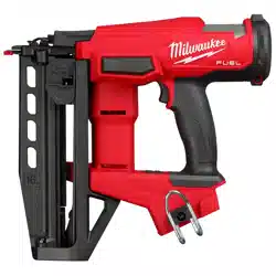
FUNCTIONAL DESCRIPTION
5
1
2
3
4
1. Trigger
2. Handle
3. Hook
4. Power/Actuation
selection
5. Nail slot
6. Magazine
7. Pusher
8. Pusher release
button
9. Workpiece contact
10. Jam latch
11. Depth adjustment
12. LED
11
12
6
7
8
9
10
SYMBOLOGY
Volts
Direct Current
Single Sequential Actuation
Contact (Bump) Actuation
Read Operator's Manual
Wear Eye Protection
Keep Hands Away
C
US
UL Listing for Canada and U.S.
Loading ...
Loading ...
Loading ...