Loading ...
Loading ...
Loading ...

Part 1 – Introduction
10
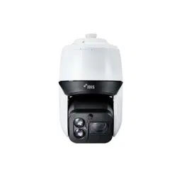
Pendant (Inner View)
1
2
3
4
1
Power
2
Network Port
3
Alarm In/Out
4
Video Out, Audio In/Out
• Network Port
Connect a network cable with an RJ-45 connector to
this port. You can congure, manage, and upgrade
this camera and monitor its images from a remote
computer over the network. For more information
on network connection setup, refer to the IDIS
Discovery operation m
anual.
The table below shows the network cable
specications.
<The network cable specications>
Item Content Note
Connector RJ-45
Ethernet 10/100Base 10/100Mbps
Cable
UTP Category
5e or higher
Maximum
length
100m
PoE
High-PoE
• Alarm In/Out
– ALI:Connect an alarm-in device to this port.
(Mechanism: Choose between an NC (Normally
Closed) type or an NO (Normally Open) type) →
Connect a mechanical or electrical switch to the
alarm in port and the GND (ground) connector.
Alarm in range is 0V to 5V. In order to detect alarm
input from an electrical switch, the signal must be
higher than 4.3V from an NC switch or less than
0.3V from an NO switch and must last for longer
than 0.5 seconds.
– ALO: It is the BJT (Bipolar Junction Transistor) -
open collector output. If the voltage and current
exceed the specication limit (Max load: 50mA,
Max Voltage: 30VDC), the product could be
damaged. When connecting the device which
exceeds the specication limit, refer to the picture
(circuit) below.
If used with an external inductive load(e.g. relay),
a diode must be connected in parallerl with
the load for protection. Otherwise, the product
could be damaged.
• Audio In/Out
DC-S6881HRX / DC-S6681HRX model
only
, Video Out
– A_I: Connect an audio source to this port. (line in)
– A_O: Connect an amplier to this port (line out).
This device does not feature a built-in audio
amplier unit and therefore requires the user to
purchase a separate speaker system with a built-in
amplier.
– V_O, GND: Connect the cable's signal line and
ground line to these ports and the connector on
its opposite end to a monitor. Use these ports
for previewing video and not monitoring video.
Go to Remote Setup (Video – Camera menu >
Miscellaneous tab) and choose a video out signal.
(NTSC or PAL)
Loading ...
Loading ...
Loading ...