
GEARED HAND WINCHES
MODEL NO’S: GWC1200B.V2, GWC2500B,
GWE1200B.V2, GWW1200B.V2
Thank you for purchasing a Sealey product. Manufactured to a high standard, this product will, if used according to these instructions,
and properly maintained, give you years of trouble free performance.
IMPORTANT: PLEASE READ THESE INSTRUCTIONS CAREFULLY. NOTE THE SAFE OPERATIONAL REQUIREMENTS, WARNINGS & CAUTIONS. USE
THE PRODUCT CORRECTLY AND WITH CARE FOR THE PURPOSE FOR WHICH IT IS INTENDED. FAILURE TO DO SO MAY CAUSE DAMAGE AND/OR
PERSONAL INJURY AND WILL INVALIDATE THE WARRANTY. KEEP THESE INSTRUCTIONS SAFE FOR FUTURE USE.
1. SAFETY
WARNING! The warnings, cautions and instructions discussed in this manual cannot cover all possible conditions and situations that
may occur. It must be understood that common sense and caution are factors which cannot be built into this product, but must be
applied by the operator.
1.1. READ THE MANUAL
Before using the hand winch, read the manual carefully to understand its features, limitations, and safety instructions. Follow the
manufacturer’s recommendations for installation, operation, and maintenance. Only use the winch for the task it is designed for.
1.2. INSPECT THE WINCH
Inspect the winch before each use to ensure that it’s in good condition. Check for any signs of damage, wear, or corrosion. Make sure
that all bolts, nuts, and screws are tightened properly. DO NOT use if damaged as this could lead to serious injury. Instead, contact an
authorised service agent.
1.3. USE APPROPRIATE ACCESSORIES
Use only accessories that are recommended by the manufacturer. Don’t modify or alter the winch or its accessories in any way. Fit only
appropriately rated cable, strap and hook suitable for the task for which the winch is to be used. DO NOT use any “cheater” pipe, lever,
or other device to lengthen the handle for additional leverage, as the pulley may fail causing damage and possible personal injury. If the
winch can not be operated by hand, it may be overloaded.
1.4. USE PROPER LIFTING TECHNIQUE
Use proper lifting techniques to avoid injury. Keep your back straight and lift with your legs. Maintain correct balance and footing. Don’t
twist your body while lifting. Keep your hands, body and clothing away from the winch components, cable and strap.
1.5. USE PERSONAL PROTECTIVE EQUIPMENT
Wear appropriate personal protective equipment such as gloves and safety glasses when operating the winch. Remove ill fitting
clothing. Remove ties, watches, rings and other loose jewellery, and contain and/or tie back long hair.
1.6. DO NOT EXCEED LOAD CAPACITY
This can cause damage to the winch or lead to accidents. Always check the load capacity before using the winch. Ensure you know
how much load you are winching. Never exceed the maximum pulling capacity. Take into account any angle of incline over which the load
must be pulled. Also account for winching loads from thick mud, or through snow or water. Chock the wheels of vehicles to be winched
then release any brakes and place gears in neutral, ensure the load is capable of free movement before winching. Take up the strain on
the cable or strap and remove the wheel chocks to move the load. DO NOT pull the cable or strap over or around a corner and DO NOT
take the hook around the load and hook back onto the cable.
1.7. SECURE THE LOAD
Make sure that the load is properly secured before lifting, using appropriate rigging techniques such as slings or chains. NOTE: this
winch is intended for carefully pulling a load. DO NOT use it for lifting or slinging. For a heavy load place a blanket (or jacket) over
extended cable about 2 feet away from the hook in order to lessen the severity of a cable break. Apply even and steady pressure to the
handle when releasing the tension from the load. DO NOT operate the winch with less than five wraps of cable or strap on the drum. To
avoid sideways cable slip, the cable under load should only be wound on to the drum to such an extent that a minimum space of two times
the cable diameter remains on the drum flange.
1.8. KEEP WORK AREA SAFE & CLEAR
Keep children and non-essential persons away from the work area. DO NOT operate the winch if you are tired or under the influence of
alcohol, drugs or intoxicating medication.
1.9. AUTOMATIC MECHANICAL BRAKE REQUIREMENT
The minimum pulling load required for a proper braking function on the winch is 25kg. Without this minimum load, the braking function, will
not take place.
1.10. ATTACHING THE WINCH
Most truck beds are not designed to support the pulling capacity of a winch. Choose an appropriately strong winching point, which we
recommend is reinforced with steel plates and appropriate securing bolts. The winch mounting point must be capable of withstanding 4 x
the maximum rated capacity of the winch.
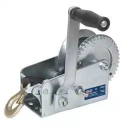
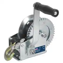
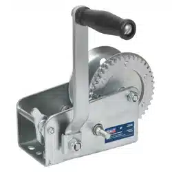
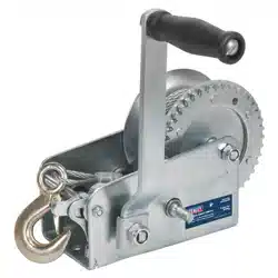
2. INTRODUCTION
Hardened steel gear with a heavy plate chassis. Includes an automatic brake system which requires a minimum force of 25kg, this
prevents the handle from kicking back and holds the load in position. Features a fully closed gearbox. Suitable for general and recovery
operations. Supplied with cable, webbing or as an empty drum (see specication table).
Refer to
instruction
manual
Wear protective
gloves
Wear eye
protection
Warning:
Crushing hands
Warning:
DO NOT
reach in
Original Language Version
© Jack Sealey Limited
GWC1200B.V2, GWC2500B, GWE1200B.V2, GWW1200B.V2 Issue 3 (2) 11/10/23
3. SPECIFICATION
MODEL NO. GWC1200B.V2 GWC2500B GWE1200B.V2 GWW1200B.V2
Supplied with Cable Cable Empty Webbing
Capacity 540kg 1130kg 540kg 540kg
Gear Ratio 4.2:1 10.0:1 4.2:1 4.2:1
Handle Length 200mm 300mm 200mm 200mm
Hub Diameter 52mm 76mm 52mm 52mm
Maximum Cable/
Webbing Size
Ø4mm x 8m
(cable supplied)
Ø5mm x 8m
(cable supplied)
Ø4mm x 8m cable
(not supplied)
48mm x 10m webbing
(not supplied)
48mm x 10m
(webbing supplied)
Min Breaking Force: 11.73kN 25.34kN N/A 14.71kN
4. ASSEMBLY
FIG.1
Cable Anchor
FIG.2 FIG.3
4.1. CONNECTING THE CRANK HANDLE - ALL MODELS
Fit Crank Handle assembly by inserting the hexagon socket of the Crank Handle onto the end of the Main Drive Axle. Make sure the
handle is tightened and secure before use.
4.2. MOUNTING (FIG.1)
Hand winches can be mounted onto a solid metal or wood structure using the mounting holes in the frame. Refer to safety section.
4.3. CONNECTING THE CABLE (FIG.2) - GWC/GWE ONLY
Before operating, the reel must first be properly spooled with cable. Weave the steel cable through the holes, starting from inside to
outside. Secure the cable to the drum by tightening the cable anchor nuts. Turn the handle and guide the cable so it seats neatly on
the drum, as shown in fig.3. Replace the cable anchor each time a cable is replaced. Note: if the cable is not properly spooled, excess
abrasion may occur, reducing the life of the cable.
4.4. CONNECTING THE WEBBING (FIG.4, 5 & 6) - GWW ONLY
Remove the gear cover to access the strap fitting bolt (fig.4) Release the strap fitting bolt shown in fig.5, and slide through the loop on the
webbing (fig.6). Secure the strap fitting bolt with nut. Reattach the gear cover. Turn the handle to wind the webbing onto the drum.
WARNING! The strap breaking strain must be at least 3 times the pulling capacity.
FIG.4
FIG.5
FIG.6
5. OPERATION
WARNING! Before using the winch ensure you read, understand and apply Section 1 Safety Instructions. Never fully extend the cable or
strap when under load. Load capacity is reduced as layers build up on the drum.
NOTE: Re-lubricate all shafts and gears before use.
5.1. PULLING
To pull a load, turn the Crank Handle clockwise. The load can be stopped in any position, by letting go of the handle.
5.2. RELEASING
To release the cable/strap, turn the Crank Handle anticlockwise. The Automatic Brake will prevent the Handle from kicking back.
WARNING! The brake function will only be activated by a minimum load of 25kg. DO NOT oil or grease the brake mechanism.
Original Language Version
© Jack Sealey Limited
GWC1200B.V2, GWC2500B, GWE1200B.V2, GWW1200B.V2 Issue 3 (2) 11/10/23

Sealey Group, Kempson Way, Suffolk Business Park, Bury St Edmunds, Suffolk. IP32 7AR
01284 757500 sales@sealey.co.uk www.sealey.co.uk
Note: It is our policy to continually improve products and as such we reserve the right to alter data, specications and component parts without prior notice.
Please note that other versions of this product are available. If you require documentation for alternative versions, please email or call our
technical team on technical@sealey.co.uk or 01284 757505.
Important: No Liability is accepted for incorrect use of this product.
Warranty: Guarantee is 12 months from purchase date, proof of which is required for any claim.
ENVIRONMENT PROTECTION
Recycle unwanted materials instead of disposing of them as waste. All tools, accessories and packaging should be
sorted, taken to a recycling centre and disposed of in a manner which is compatible with the environment. When
the product becomes completely unserviceable and requires disposal, drain any uids (if applicable) into approved
containers and dispose of the product and uids according to local regulations.
REGISTER YOUR
PURCHASE HERE
5.3. FREE SPOOL FUNCTION
To activate the Free Spool function, take off the Crank Handle, and turn the hex nut anticlockwise. The drum can now be turned freely. To
stop using the Free Spool function turn the hex nut clockwise back to the Auto Brake position. Note: With a load on the cable or strap,
you can not use the Free Spool function.
6. MAINTENANCE
9 Keep the winch, cable and strap clean.
9 Inspect cable and strap regularly checking for fraying, kinks, broken strands or distortion and replace if necessary.
9 Keep the cable and unit lightly oiled for protection.
9 Periodically grease gears, reel shaft and handle threads.
8 DO NOT get oil or grease on the brake mechanism.
Parts support is available for this product. To obtain a parts listing and/or diagram, please log on to
www.sealey.co.uk, email sales@sealey.co.uk or telephone 01284 757500
Original Language Version
© Jack Sealey Limited
GWC1200B.V2, GWC2500B, GWE1200B.V2, GWW1200B.V2 Issue 3 (2) 11/10/23